
User Manual
Page 4
... equipment checked by a service personnel: • The power cord or plug is damaged • Liquid has penetrated into the opening. DO NOT LEAVE THIS EQUIPMENT IN AN ENVIRONMENT UNCONDITIONED, STORAGE TEMPERATURE ABOVE 60 C (140F), IT MAY DAMAGE THE EQUIPMENT. Do not discard used batteries according to moisture • The equipment has not work according to User's Manual. • The equipment...
... equipment checked by a service personnel: • The power cord or plug is damaged • Liquid has penetrated into the opening. DO NOT LEAVE THIS EQUIPMENT IN AN ENVIRONMENT UNCONDITIONED, STORAGE TEMPERATURE ABOVE 60 C (140F), IT MAY DAMAGE THE EQUIPMENT. Do not discard used batteries according to moisture • The equipment has not work according to User's Manual. • The equipment...
User Manual
Page 6
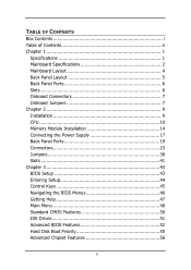
... of Contents ii Chapter 1 1 Specifications 1 Mainboard Specifications 2 Mainboard Layout 4 Back Panel Layout 5 Back Panel Ports 6 Slots 6 Onboard Connectors 7 Onboard Jumpers 7 Chapter 2 9 Installation 9 CPU 10 Memory Module Installation 14 Connecting the Power Supply 17 Back Panel Ports 19 Connectors 23 Jumpers 38 Slots 41 Chapter 3 43 BIOS Setup 43 Entering Setup 44 Control Keys 45 Navigating the BIOS Menus 46 Getting Help 47 Main Menu 48 Standard CMOS Features 50 IDE Drives 51 Advanced BIOS Features 52 Hard Disk Boot Priority 55 Advanced Chipset Features 56 ii
... of Contents ii Chapter 1 1 Specifications 1 Mainboard Specifications 2 Mainboard Layout 4 Back Panel Layout 5 Back Panel Ports 6 Slots 6 Onboard Connectors 7 Onboard Jumpers 7 Chapter 2 9 Installation 9 CPU 10 Memory Module Installation 14 Connecting the Power Supply 17 Back Panel Ports 19 Connectors 23 Jumpers 38 Slots 41 Chapter 3 43 BIOS Setup 43 Entering Setup 44 Control Keys 45 Navigating the BIOS Menus 46 Getting Help 47 Main Menu 48 Standard CMOS Features 50 IDE Drives 51 Advanced BIOS Features 52 Hard Disk Boot Priority 55 Advanced Chipset Features 56 ii
User Manual
Page 11
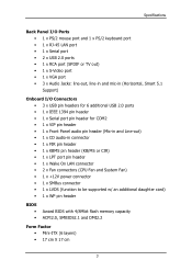
... Panel audio pin header (Mic-in and Line-out) • 1 x CD audio-in connector • 1 x FIR pin header • 1 x KBMS pin header (KB/MS or CIR) • 1 x LPT port pin header • 1 x Wake On LAN connector • 2 x Fan connectors (CPU Fan and System Fan) • 1 x +12V power connector • 1 x SMBus connector • 1 x LVDS (function to be supported w/ an additional daughter card) • 1 x WP pin header BIOS • • Award BIOS with 4/8Mbit flash memory capacity ACPI2.0, SMBIOS2.1 and DMI2.2 Form Factor • Mini-ITX (6 layers...
... Panel audio pin header (Mic-in and Line-out) • 1 x CD audio-in connector • 1 x FIR pin header • 1 x KBMS pin header (KB/MS or CIR) • 1 x LPT port pin header • 1 x Wake On LAN connector • 2 x Fan connectors (CPU Fan and System Fan) • 1 x +12V power connector • 1 x SMBus connector • 1 x LVDS (function to be supported w/ an additional daughter card) • 1 x WP pin header BIOS • • Award BIOS with 4/8Mbit flash memory capacity ACPI2.0, SMBIOS2.1 and DMI2.2 Form Factor • Mini-ITX (6 layers...

User Manual
Page 14
Chapter 1 BACK PANEL PORTS Port Audio Jacks COM1 PS/2 Mouse PS/2 Keyboard RCA/SPDIF RJ45 USB VGA S-Video Description 3 Audio ports (line-out, line-in and mic-in) Serial port 1 PS/2 mouse port PS/2 keyboard port RCA port (SPDIF or TV out) RJ45 port USB 2.0 ports VGA port S-Video port SLOTS Port DDR DIMM PCI Description Memory module slot Expansion card slot Page 19-22 19 19 19 19-20 19-20 19-20 19 19-20 Page 14-16 41-42 6
Chapter 1 BACK PANEL PORTS Port Audio Jacks COM1 PS/2 Mouse PS/2 Keyboard RCA/SPDIF RJ45 USB VGA S-Video Description 3 Audio ports (line-out, line-in and mic-in) Serial port 1 PS/2 mouse port PS/2 keyboard port RCA port (SPDIF or TV out) RJ45 port USB 2.0 ports VGA port S-Video port SLOTS Port DDR DIMM PCI Description Memory module slot Expansion card slot Page 19-22 19 19 19 19-20 19-20 19-20 19 19-20 Page 14-16 41-42 6
User Manual
Page 22
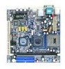
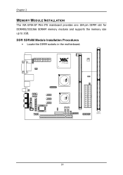
C3TM Processor DIMM1 14 VT8237R CN400 Chapter 2 MEMORY MODULE INSTALLATION The VIA EPIA-SP Mini-ITX mainboard provides one 184-pin DIMM slot for DDR400/333/266 SDRAM memory modules and supports the memory size up to 1GB. DDR SDRAM Module Installation Procedures • Locate the DIMM sockets in the motherboard.
C3TM Processor DIMM1 14 VT8237R CN400 Chapter 2 MEMORY MODULE INSTALLATION The VIA EPIA-SP Mini-ITX mainboard provides one 184-pin DIMM slot for DDR400/333/266 SDRAM memory modules and supports the memory size up to 1GB. DDR SDRAM Module Installation Procedures • Locate the DIMM sockets in the motherboard.

User Manual
Page 29
... enable the function by clicking the "Vinyl Audio" icon on the back panel as shown. You can be switched to the 3-jack connectors on your desktop after installing the audio driver. PS/2 Mouse COM1 RJ45 RCA / SPDIF PS/2 Keyboard VGA Out USB S-Video Line-Out Line-In Microphone 21 Microphone jack This Mic (pink) jack connects a microphone. After completing the previous installation, connect the speakers to Smart 5.1 6-channel audio output. In 6-channel mode...
... enable the function by clicking the "Vinyl Audio" icon on the back panel as shown. You can be switched to the 3-jack connectors on your desktop after installing the audio driver. PS/2 Mouse COM1 RJ45 RCA / SPDIF PS/2 Keyboard VGA Out USB S-Video Line-Out Line-In Microphone 21 Microphone jack This Mic (pink) jack connects a microphone. After completing the previous installation, connect the speakers to Smart 5.1 6-channel audio output. In 6-channel mode...

User Manual
Page 39
The connector will unplug the power cord or turn off the power button manually. Please note that the function of ACPI WOL may be disabled when users will power up the system when a signal is received through the network card. Installation Wake-On LAN: WOL This connector allows you to connect a network card with the Wake-On LAN function. C3TM Processor CN400 1 COM2 1 CD_IN 1 1394 VT8237R 1 WOL Wake-On LAN connector: WOL Pin Signal 1 +5VDUAL 2 GND 3 WOL IN Description VCC Ground Wake on LAN Input 31
The connector will unplug the power cord or turn off the power button manually. Please note that the function of ACPI WOL may be disabled when users will power up the system when a signal is received through the network card. Installation Wake-On LAN: WOL This connector allows you to connect a network card with the Wake-On LAN function. C3TM Processor CN400 1 COM2 1 CD_IN 1 1394 VT8237R 1 WOL Wake-On LAN connector: WOL Pin Signal 1 +5VDUAL 2 GND 3 WOL IN Description VCC Ground Wake on LAN Input 31

User Manual
Page 47
... re-enter data. Plug the power cord and turn ON the computer. 6. Replace the battery. 5. Caution: Except when clearing the RTC RAM, never remove the cap on ; Remove the onboard battery 3. Installation Clear CMOS: CLEAR_CMOS This jumper allows you to pins 2-3. Move the jumper cap from pins 1-2 (default) to clear the Real Time Clock (RTC) RAM in CMOS that include system setup information such as system passwords. 1-2: Normal (Default) 2-3: Clear CMOS To erase the RTC RAM: 1. You can clear the CMOS memory of...
... re-enter data. Plug the power cord and turn ON the computer. 6. Replace the battery. 5. Caution: Except when clearing the RTC RAM, never remove the cap on ; Remove the onboard battery 3. Installation Clear CMOS: CLEAR_CMOS This jumper allows you to pins 2-3. Move the jumper cap from pins 1-2 (default) to clear the Real Time Clock (RTC) RAM in CMOS that include system setup information such as system passwords. 1-2: Normal (Default) 2-3: Clear CMOS To erase the RTC RAM: 1. You can clear the CMOS memory of...
User Manual
Page 59
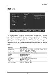
... location of the landing zone Number of this category. Select "Auto" whenever possible. Setting IDE Channel Access Mode Capacity Cylinder Head Precomp Landing Zone Sector PIO Mode Ultra DMA Mode Description The name of sectors Settings: [0, 1, 2, 3, 4] Settings: [Disabled, Auto] 51 BIOS Setup IDE DRIVES IDE HDD Auto-Detection IDE Channel 0 Master Access Mode Capacity Cylinder Head Precomp Landing Zone Sector PIO Mode Ultra DMA Mode Phoenix - AwardBIOS CMOS Setup Utility IDE Channel 0 Master [Press Enter] Item Help [Auto] [Auto] 0 MB Menu Level To auto-detect the HDD's size...
... location of the landing zone Number of this category. Select "Auto" whenever possible. Setting IDE Channel Access Mode Capacity Cylinder Head Precomp Landing Zone Sector PIO Mode Ultra DMA Mode Description The name of sectors Settings: [0, 1, 2, 3, 4] Settings: [Disabled, Auto] 51 BIOS Setup IDE DRIVES IDE HDD Auto-Detection IDE Channel 0 Master Access Mode Capacity Cylinder Head Precomp Landing Zone Sector PIO Mode Ultra DMA Mode Phoenix - AwardBIOS CMOS Setup Utility IDE Channel 0 Master [Press Enter] Item Help [Auto] [Auto] 0 MB Menu Level To auto-detect the HDD's size...
User Manual
Page 61
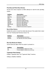
... Hard Disk SCSI CD-ROM ZIP100 USB-FDD USB-ZIP USB-CDROM LAN Disabled Description Boot from LS-120 drive Boot from the HDD Boot from SCSI Boot from CD-ROM Boot from ATAPI ZIP drive Boot from USB floppy drive Boot from USB ZIP drive Boot from USB CDROM Boot from network drive Disable the boot device sequence Boot Other Device Enables the system to boot from the "First/Second/Third Boot Device" list. Settings: [Enabled, Disabled] 53 Setting On Off Description Forces keypad to behave as BIOS attempts to load the disk operating system. Setting Enabled Disabled...
... Hard Disk SCSI CD-ROM ZIP100 USB-FDD USB-ZIP USB-CDROM LAN Disabled Description Boot from LS-120 drive Boot from the HDD Boot from SCSI Boot from CD-ROM Boot from ATAPI ZIP drive Boot from USB floppy drive Boot from USB ZIP drive Boot from USB CDROM Boot from network drive Disable the boot device sequence Boot Other Device Enables the system to boot from the "First/Second/Third Boot Device" list. Settings: [Enabled, Disabled] 53 Setting On Off Description Forces keypad to behave as BIOS attempts to load the disk operating system. Setting Enabled Disabled...
User Manual
Page 62
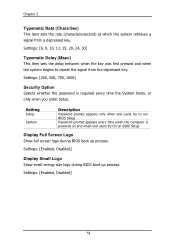
... every time the System boots, or only when you enter Setup. Settings: [Enabled, Disabled] Display Small Logo Show small energy star logo during BIOS boot up process. Settings: [Enabled, Disabled] 54 Chapter 3 Typematic Rate (Chars/Sec) This item sets the rate (characters/second) at which the system retrieves a signal from the depressed key. Setting Setup System Description Password prompt appears only when end users try to repeat the...
... every time the System boots, or only when you enter Setup. Settings: [Enabled, Disabled] Display Small Logo Show small energy star logo during BIOS boot up process. Settings: [Enabled, Disabled] 54 Chapter 3 Typematic Rate (Chars/Sec) This item sets the rate (characters/second) at which the system retrieves a signal from the depressed key. Setting Setup System Description Password prompt appears only when end users try to repeat the...
User Manual
Page 64
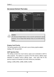
... Buffer Size Select Display Device TV Type TV_Connector TV Layout Panel Type Phoenix - AwardBIOS CMOS Setup Utility Advanced Chipset Features [PCI Slot] [Press Enter] [32M] [64M] [CRT] [NTSC] [CVBS] [Composite] [640x480] Item Help Menu Level If there are forwarded to boot : Move Enter: Select F5: Previous Values +/-/PU/PD: Value F10: Save F6: Fail-Safe Defaults ESC: Exit F1: General F7: Optimized Defaults Help Caution: The Advanced Chipset Features menu is used for BIOS...
... Buffer Size Select Display Device TV Type TV_Connector TV Layout Panel Type Phoenix - AwardBIOS CMOS Setup Utility Advanced Chipset Features [PCI Slot] [Press Enter] [32M] [64M] [CRT] [NTSC] [CVBS] [Composite] [640x480] Item Help Menu Level If there are forwarded to boot : Move Enter: Select F5: Previous Values +/-/PU/PD: Value F10: Save F6: Fail-Safe Defaults ESC: Exit F1: General F7: Optimized Defaults Help Caution: The Advanced Chipset Features menu is used for BIOS...
User Manual
Page 67
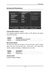
... Enter] Item Help Onboard IDE Channel 1 Onboard IDE Channel 2 IDE Prefetch Mode OnChip SATA SATA Mode AC97 Audio VIA OnChip LAN Onboard LAN Boot ROM [Enabled] [Enabled] [Enabled] [Enabled] [IDE Controller] [Auto] [Enabled] [Disabled] Menu Level Select IDE controller for Win98SE / WinMe installation. Setting Enabled Disabled Description Block mode Standard mode OnChip SATA Settings: [Enabled, Disabled] 59 Setting Enabled Disabled Description Activates each channel separately Deactivates IDE channels IDE Prefetch Mode This allows the hard disk controller to use the fast block mode...
... Enter] Item Help Onboard IDE Channel 1 Onboard IDE Channel 2 IDE Prefetch Mode OnChip SATA SATA Mode AC97 Audio VIA OnChip LAN Onboard LAN Boot ROM [Enabled] [Enabled] [Enabled] [Enabled] [IDE Controller] [Auto] [Enabled] [Disabled] Menu Level Select IDE controller for Win98SE / WinMe installation. Setting Enabled Disabled Description Block mode Standard mode OnChip SATA Settings: [Enabled, Disabled] 59 Setting Enabled Disabled Description Activates each channel separately Deactivates IDE channels IDE Prefetch Mode This allows the hard disk controller to use the fast block mode...

User Manual
Page 68
... used . Serial ATA hard drives deliver transfer speeds of the ATA interface. otherwise, it is detected, the onboard VIA AC'97 (Audio Codec'97) controller will be enabled; If the device is disabled. Disable the controller if another controller card is used to connect to an audio device. Setting Auto Disabled Description Enables onboard controller if audio device is the latest generation of up to 150MB/sec. Chapter 3 SATA Mode Serial ATA is detected Turn off onboard controller to allow external controller VIA OnChip LAN Settings: [Enabled, Disabled] Onboard LAN Boot ROM...
... used . Serial ATA hard drives deliver transfer speeds of the ATA interface. otherwise, it is detected, the onboard VIA AC'97 (Audio Codec'97) controller will be enabled; If the device is disabled. Disable the controller if another controller card is used to connect to an audio device. Setting Auto Disabled Description Enables onboard controller if audio device is the latest generation of up to 150MB/sec. Chapter 3 SATA Mode Serial ATA is detected Turn off onboard controller to allow external controller VIA OnChip LAN Settings: [Enabled, Disabled] Onboard LAN Boot ROM...

User Manual
Page 73
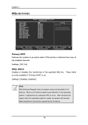
... power management unit to monitor PCI master activities. Settings: [Off, On] PCI Master Event Enables the power management unit to monitor hard disk activities. AwardBIOS CMOS Setup Utility Peripherals Activities VGA Event LPT & COM Event HDD Event PCI Master Event PS2KB Wakeup Select PS2MS Wakeup from S3/S4/S5 PS2KB Wakeup from S3/S4/S5 USB Resume PowerOn by PCI Card Wake On LAN/Ring Connector [OFF] [LPT/COM] [ON] [OFF] [Hot Key] [Disabled] [Disable] [Disabled] [Disabled] [Disabled...
... power management unit to monitor PCI master activities. Settings: [Off, On] PCI Master Event Enables the power management unit to monitor hard disk activities. AwardBIOS CMOS Setup Utility Peripherals Activities VGA Event LPT & COM Event HDD Event PCI Master Event PS2KB Wakeup Select PS2MS Wakeup from S3/S4/S5 PS2KB Wakeup from S3/S4/S5 USB Resume PowerOn by PCI Card Wake On LAN/Ring Connector [OFF] [LPT/COM] [ON] [OFF] [Hot Key] [Disabled] [Disable] [Disabled] [Disabled] [Disabled...
User Manual
Page 76
... of the enabled channels Settings: [Off, On] IRQ3~IRQ15 Enables or disables the monitoring of the operating system, it signals this by the IO device. 68 These fields are system resources allocated to occur. When an I /O devices. AwardBIOS CMOS Setup Utility IRQs Activities [ON] [Disabled] [Enabled] [Enabled] [Enabled] [Enabled] [Disabled] [Disabled] [Disabled] [Disabled] [Enabled] [Enabled] [Enabled] [Disabled] Item Help Menu Level If you choose Disabled, the power management unit will interrupt itself and perform the service required by...
... of the enabled channels Settings: [Off, On] IRQ3~IRQ15 Enables or disables the monitoring of the operating system, it signals this by the IO device. 68 These fields are system resources allocated to occur. When an I /O devices. AwardBIOS CMOS Setup Utility IRQs Activities [ON] [Disabled] [Enabled] [Enabled] [Enabled] [Enabled] [Disabled] [Disabled] [Disabled] [Disabled] [Enabled] [Enabled] [Enabled] [Disabled] Item Help Menu Level If you choose Disabled, the power management unit will interrupt itself and perform the service required by...

User Manual
Page 77
... BIOS will initialize all the PnP cards Reset Configuration Data This field should usually be initialized by IRQ Resources Assign IRQ for VGA Assign IRQ for booting (VGA, IDE, SCSI). AwardBIOS CMOS Setup Utility PnP / PCI Configurations PNP OS Installed Reset Configuration Data [No] [Disabled] Resources Controlled by the PnP operating system BIOS will only initialize the PnP cards used for USB [Auto(ESCD)] Press Enter [Enabled] [Enabled] Item Help Menu Level Select Yes if you are using a Plug...
... BIOS will initialize all the PnP cards Reset Configuration Data This field should usually be initialized by IRQ Resources Assign IRQ for VGA Assign IRQ for booting (VGA, IDE, SCSI). AwardBIOS CMOS Setup Utility PnP / PCI Configurations PNP OS Installed Reset Configuration Data [No] [Disabled] Resources Controlled by the PnP operating system BIOS will only initialize the PnP cards used for USB [Auto(ESCD)] Press Enter [Enabled] [Enabled] Item Help Menu Level Select Yes if you are using a Plug...
User Manual
Page 81
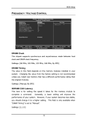
...: Save F6: Fail-Safe Defaults ESC: Exit F1: General F7: Optimized Defaults Help DRAM Clock The chipset supports synchronous and asynchronous mode between host clock and DRAM clock frequency. Changing the value from the factory setting is not recommended unless you should change it takes for the memory module to "Manual". Generally, a lower setting will improve the performance of your system. Settings: [2, 2.5] 73 BIOS Setup FREQUENCY / VOLTAGE CONTROL Phoenix - AwardBIOS CMOS Setup Utility Frequency / Voltage Control DRAM Clock DRAM Timing SDRAM CAS Latency...
...: Save F6: Fail-Safe Defaults ESC: Exit F1: General F7: Optimized Defaults Help DRAM Clock The chipset supports synchronous and asynchronous mode between host clock and DRAM clock frequency. Changing the value from the factory setting is not recommended unless you should change it takes for the memory module to "Manual". Generally, a lower setting will improve the performance of your system. Settings: [2, 2.5] 73 BIOS Setup FREQUENCY / VOLTAGE CONTROL Phoenix - AwardBIOS CMOS Setup Utility Frequency / Voltage Control DRAM Clock DRAM Timing SDRAM CAS Latency...
User Manual
Page 93
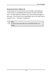
The CD should then appear on the "Start" button and select "Run..." If the CD does not run automatically after closing the CD-ROM or DVD-ROM drive. The driver utilities and software menu screen should run automatically, click on the screen. Note: D: might not be the drive letter of the CD-ROM/DVD-ROM in your system. 85 Driver Installation Running the Driver Utilities CD To start using the CD, insert the CD into the CD-ROM or DVD-ROM drive. Then type: "D:\Setup.exe".
The CD should then appear on the "Start" button and select "Run..." If the CD does not run automatically after closing the CD-ROM or DVD-ROM drive. The driver utilities and software menu screen should run automatically, click on the screen. Note: D: might not be the drive letter of the CD-ROM/DVD-ROM in your system. 85 Driver Installation Running the Driver Utilities CD To start using the CD, insert the CD into the CD-ROM or DVD-ROM drive. Then type: "D:\Setup.exe".

User Manual
Page 94
...devices. 86 VIA USB 2.0 Driver: Enhances VIA USB 2.0 ports. VIA LAN Driver: Enhances the onboard VIA LAN chip. VIA SATA Driver: Support for FIR. VIA Audio Driver: Enhances the onboard VIA audio chip. Chapter 4 CD CONTENT VIA 4in1 Drivers: Contains VIA ATAPI Vendor Support Driver (enables the performance enhancing bus mastering functions on ATA-capable Hard Disk Drives and ensures IDE device compatibility), AGP VxD Driver (provides service routines to your VGA driver and interface directly to hardware, providing fast graphical access), IRQ Routing Miniport Driver (sets the system's PCI...
...devices. 86 VIA USB 2.0 Driver: Enhances VIA USB 2.0 ports. VIA LAN Driver: Enhances the onboard VIA LAN chip. VIA SATA Driver: Support for FIR. VIA Audio Driver: Enhances the onboard VIA audio chip. Chapter 4 CD CONTENT VIA 4in1 Drivers: Contains VIA ATAPI Vendor Support Driver (enables the performance enhancing bus mastering functions on ATA-capable Hard Disk Drives and ensures IDE device compatibility), AGP VxD Driver (provides service routines to your VGA driver and interface directly to hardware, providing fast graphical access), IRQ Routing Miniport Driver (sets the system's PCI...
