User Manual
Page 1
EPIA-M700 User's Manual Version 1.03 September 25, 2008
EPIA-M700 User's Manual Version 1.03 September 25, 2008
User Manual
Page 2
...be used in order to correct the interference at any means, electronic, mechanical, magnetic, optical, chemical, manual or otherwise without obligation to change . No part of VIA Technologies, Incorporated. This equipment generates, uses and can radiate radio frequency energy and, if not installed ...and used in accordance with the instruction manual, may arise from the use or misuse of such change at...
...be used in order to correct the interference at any means, electronic, mechanical, magnetic, optical, chemical, manual or otherwise without obligation to change . No part of VIA Technologies, Incorporated. This equipment generates, uses and can radiate radio frequency energy and, if not installed ...and used in accordance with the instruction manual, may arise from the use or misuse of such change at...

User Manual
Page 3
... connecting the equipment to local regulations. If any add-on the equipment should be damaged. Caution: Only use the appropriate battery specified for this User's Manual for air convection hence protects the equipment from humidity. Keep this product. All cautions and warnings on card or module. Do not reuse, recharge, or...
... connecting the equipment to local regulations. If any add-on the equipment should be damaged. Caution: Only use the appropriate battery specified for this User's Manual for air convection hence protects the equipment from humidity. Keep this product. All cautions and warnings on card or module. Do not reuse, recharge, or...
User Manual
Page 9
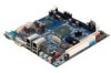
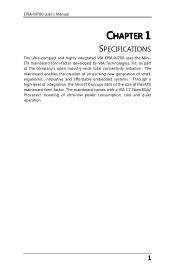
...of integration, the Mini-ITX occupy 66% of the size of the company's open industry-wide total connectivity initiative. The mainboard comes with a VIA C7 NanoBGA2 Processor, boasting of ultra-low power consumption, cool and quiet operation. 1 EPIA-M700 User's Manual CHHAAPPTTEERR 1 SPECIFICATIONS ...The ultra-compact and highly integrated VIA EPIA-M700 uses the MiniITX mainboard form-factor...
...of integration, the Mini-ITX occupy 66% of the size of the company's open industry-wide total connectivity initiative. The mainboard comes with a VIA C7 NanoBGA2 Processor, boasting of ultra-low power consumption, cool and quiet operation. 1 EPIA-M700 User's Manual CHHAAPPTTEERR 1 SPECIFICATIONS ...The ultra-compact and highly integrated VIA EPIA-M700 uses the MiniITX mainboard form-factor...

User Manual
Page 10
EPIA-M700 User's Manual Mainboard Specifications CPU • VIA C7 1.0GHz / 1.5GHz NanoBGA2 processor Chipset • VIA VX800 advanced all-in-one system processor Graphics • Integrated VIA Chrome9™ HC DX9 3D/2D Graphics and Unified Video Decoding Accelerator Audio • VIA VT1708B High Definition ... (up to 2 GB) Expansion Slot • 1 x PCI slot IDE • 1 x UltraDMA 133/100/66/33 pin header LAN • 2 x VIA VT6130 PCIe Gigabit Ethernet Controllers Onboard I/O Connectors • 1 x USB pin header for 2 additional USB 2.0 ports • 1 x Digital video input pin header...
EPIA-M700 User's Manual Mainboard Specifications CPU • VIA C7 1.0GHz / 1.5GHz NanoBGA2 processor Chipset • VIA VX800 advanced all-in-one system processor Graphics • Integrated VIA Chrome9™ HC DX9 3D/2D Graphics and Unified Video Decoding Accelerator Audio • VIA VT1708B High Definition ... (up to 2 GB) Expansion Slot • 1 x PCI slot IDE • 1 x UltraDMA 133/100/66/33 pin header LAN • 2 x VIA VT6130 PCIe Gigabit Ethernet Controllers Onboard I/O Connectors • 1 x USB pin header for 2 additional USB 2.0 ports • 1 x Digital video input pin header...
User Manual
Page 11
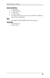
EPIA-M700 User's Manual Back Panel I/O Ports • 1 x Serial port • 2 x RJ45 LAN ports • 1 x DVI-I port • 4 x USB 2.0 ports • 3 x Audio phone jacks: Line-out, Line-in and MIC-in (Horizontal type, Smart 5.1 supported) BIOS • Award BIOS with SPI 4/8Mbit flash memory capacity Form Factor • Mini-ITX (6-layer) • 17cm X 17cm 3
EPIA-M700 User's Manual Back Panel I/O Ports • 1 x Serial port • 2 x RJ45 LAN ports • 1 x DVI-I port • 4 x USB 2.0 ports • 3 x Audio phone jacks: Line-out, Line-in and MIC-in (Horizontal type, Smart 5.1 supported) BIOS • Award BIOS with SPI 4/8Mbit flash memory capacity Form Factor • Mini-ITX (6-layer) • 17cm X 17cm 3

User Manual
Page 15
EPIA-M700 User's Manual CHHAAPPTTEERR 2 INSTALLATION This chapter provides you with information about hardware installation procedures. It is recommended to use a grounded wrist strap before handling computer components. Electrostatic discharge (ESD) can damage some components. 7
EPIA-M700 User's Manual CHHAAPPTTEERR 2 INSTALLATION This chapter provides you with information about hardware installation procedures. It is recommended to use a grounded wrist strap before handling computer components. Electrostatic discharge (ESD) can damage some components. 7

User Manual
Page 16
... GND CPU_FAN Pin Signal 1 F_IO2 2 +12V 3 GND SYS_FAN 8 EPIA-M700 User's Manual CPU The VIA EPIA-M700 mainboard is Ground and should be connected to the +12V. The black wire is packaged with fan while VIA C7 1.0 GHz requires only a heatsink. 120 240 1.8V 1 121 CPU Fan and ...CPU_FAN (CPU fan) and SYS_FAN (system fan) run on +12V and maintain system cooling. To provide sufficient cooling, VIA C7 1.5 GHz processor requires a heatsink with a standard VIA C7 1.5 GHz / 1.0 GHz NanoBGA2 processor. When connecting the wire to the connectors, always be aware that the red...
... GND CPU_FAN Pin Signal 1 F_IO2 2 +12V 3 GND SYS_FAN 8 EPIA-M700 User's Manual CPU The VIA EPIA-M700 mainboard is Ground and should be connected to the +12V. The black wire is packaged with fan while VIA C7 1.0 GHz requires only a heatsink. 120 240 1.8V 1 121 CPU Fan and ...CPU_FAN (CPU fan) and SYS_FAN (system fan) run on +12V and maintain system cooling. To provide sufficient cooling, VIA C7 1.5 GHz processor requires a heatsink with a standard VIA C7 1.5 GHz / 1.0 GHz NanoBGA2 processor. When connecting the wire to the connectors, always be aware that the red...
User Manual
Page 17
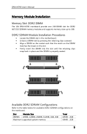
DDR2 SDRAM Module Installation Procedures • Locate the DIMM slot in the motherboard. • Unlock a DIMM slot by pressing the retaining clips outward. • Align a DIMM on the socket such that the notch on the DIMM matches the ..., 1GB, 2GB Maximum supported system memory Total 64MB - 2GB 64MB - 2GB 9 Available DDR2 SDRAM Configurations Refer to 2GB. EPIA-M700 User's Manual Memory Module Installation Memory Slot: DDR2 DIMM The VIA EPIA-M700 mainboard provide one 240-DIMM slot for DDR2 667/533 SDRAM memory modules and supports memory sizes up to...
DDR2 SDRAM Module Installation Procedures • Locate the DIMM slot in the motherboard. • Unlock a DIMM slot by pressing the retaining clips outward. • Align a DIMM on the socket such that the notch on the DIMM matches the ..., 1GB, 2GB Maximum supported system memory Total 64MB - 2GB 64MB - 2GB 9 Available DDR2 SDRAM Configurations Refer to 2GB. EPIA-M700 User's Manual Memory Module Installation Memory Slot: DDR2 DIMM The VIA EPIA-M700 mainboard provide one 240-DIMM slot for DDR2 667/533 SDRAM memory modules and supports memory sizes up to...
User Manual
Page 18
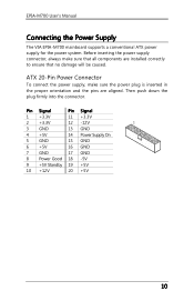
... 10 +12V 20 +5V 10 ATX 20-Pin Power Connector To connect the power supply, make sure that all components are aligned. EPIA-M700 User's Manual Connecting the Power Supply The VIA EPIA-M700 mainboard supports a conventional ATX power supply for the power system.
... 10 +12V 20 +5V 10 ATX 20-Pin Power Connector To connect the power supply, make sure that all components are aligned. EPIA-M700 User's Manual Connecting the Power Supply The VIA EPIA-M700 mainboard supports a conventional ATX power supply for the power system.

User Manual
Page 19
....0 devices. USB Ports Four standard USB 2.0 ports are provided on the back panel. The Mic jack is for connecting to a microphone. 11 EPIA-M700 User's Manual Back Panel Ports The back panel has the following ports: Gigabit Ethernet RJ-45 Ports Line-In Com Port DVI-I port allows you to connect...
....0 devices. USB Ports Four standard USB 2.0 ports are provided on the back panel. The Mic jack is for connecting to a microphone. 11 EPIA-M700 User's Manual Back Panel Ports The back panel has the following ports: Gigabit Ethernet RJ-45 Ports Line-In Com Port DVI-I port allows you to connect...
User Manual
Page 20
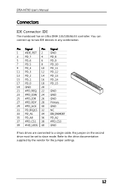
... up to the drive documentation supplied by the vendor for the jumper settings. 12 Refer to two IDE devices in any combination. EPIA-M700 User's Manual Connectors IDE Connector: IDE The mainboard has an Ultra DMA 133/100/66/33 controller. Pin Signal Pin 1 #IDE_RST 2 3 PD_7 4 5 PD_6 6 7 PD_5 8 9 PD_4 10 11...
... up to the drive documentation supplied by the vendor for the jumper settings. 12 Refer to two IDE devices in any combination. EPIA-M700 User's Manual Connectors IDE Connector: IDE The mainboard has an Ultra DMA 133/100/66/33 controller. Pin Signal Pin 1 #IDE_RST 2 3 PD_7 4 5 PD_6 6 7 PD_5 8 9 PD_4 10 11...

User Manual
Page 21
... Signal 1 +5VDUAL 3 NC 5 GND 7 KB_DT 9 KB_CK Pin Signal 2 +5VDUAL 4 6 GND 8 MS_DT 10 MS_CK Note: When the pin header is not in use. EPIA-M700 User's Manual SATA Ports These next generation connectors support the thin SATA cables for primary internal storage devices.
... Signal 1 +5VDUAL 3 NC 5 GND 7 KB_DT 9 KB_CK Pin Signal 2 +5VDUAL 4 6 GND 8 MS_DT 10 MS_CK Note: When the pin header is not in use. EPIA-M700 User's Manual SATA Ports These next generation connectors support the thin SATA cables for primary internal storage devices.

User Manual
Page 22
EPIA-M700 User's Manual Front Panel Audio: F_Audio This pin header is for the VIA front panel audio cable that allow convenient connection and control of audio devices. Pin Signal 1 MIC2_FR_L 3 MIC2_FR_R 5 LINE_OUT_R 7 FNT_IO_SENSE 9 LINE_OUT_L 11 +12V 13 AGND Pin ...
EPIA-M700 User's Manual Front Panel Audio: F_Audio This pin header is for the VIA front panel audio cable that allow convenient connection and control of audio devices. Pin Signal 1 MIC2_FR_L 3 MIC2_FR_R 5 LINE_OUT_R 7 FNT_IO_SENSE 9 LINE_OUT_L 11 +12V 13 AGND Pin ...
User Manual
Page 23
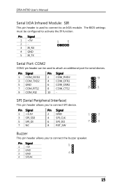
... configured to attach an additional port for serial devices. SPI (Serial Peripheral Interface) This pin header allows you to an IrDA module. EPIA-M700 User's Manual Serial IrDA Infrared Module: SIR This pin header is used to activate the IR function.
... configured to attach an additional port for serial devices. SPI (Serial Peripheral Interface) This pin header allows you to an IrDA module. EPIA-M700 User's Manual Serial IrDA Infrared Module: SIR This pin header is used to activate the IR function.

User Manual
Page 24
EPIA-M700 User's Manual DVP (Digital Video Port) This female connector works the interface to display devices, which allows you to an external Dolby Digital Decoder. The feature is ...
EPIA-M700 User's Manual DVP (Digital Video Port) This female connector works the interface to display devices, which allows you to an external Dolby Digital Decoder. The feature is ...
User Manual
Page 25
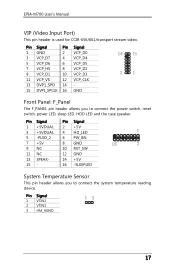
Pin Signal 1 +5VDUAL 3 +5VDUAL 5 -PLED_2 7 +5V 9 NC 11 NC 13 SPEAK15 - Pin Signal 1 VTIN2 2 VTIN2 3 HM_AGND 17 EPIA-M700 User's Manual VIP (Video Input Port) This pin header is used for CCIR-656/601/transport stream video. Pin Signal Pin Signal 1 GND 2 VCP_D0 3 VCP_D7 4 VCP_D4 5 VCP_D6 6 ...
Pin Signal 1 +5VDUAL 3 +5VDUAL 5 -PLED_2 7 +5V 9 NC 11 NC 13 SPEAK15 - Pin Signal 1 VTIN2 2 VTIN2 3 HM_AGND 17 EPIA-M700 User's Manual VIP (Video Input Port) This pin header is used for CCIR-656/601/transport stream video. Pin Signal Pin Signal 1 GND 2 VCP_D0 3 VCP_D7 4 VCP_D4 5 VCP_D6 6 ...

User Manual
Page 26
... damage the mainboard. Clear CMOS Connector: CLEAR_CMOS1 The onboard CMOS RAM stores system configuration data and has an onboard battery power supply. EPIA-M700 User's Manual Jumpers The mainboard provides jumpers for the CF Connector: V_CF_SEL This VCC selector jumper is to pins 2 and 3 afterwards. This section will damage the mainboard...
... damage the mainboard. Clear CMOS Connector: CLEAR_CMOS1 The onboard CMOS RAM stores system configuration data and has an onboard battery power supply. EPIA-M700 User's Manual Jumpers The mainboard provides jumpers for the CF Connector: V_CF_SEL This VCC selector jumper is to pins 2 and 3 afterwards. This section will damage the mainboard...

User Manual
Page 27
...: CF This CF connector allows you to insert PCI expansion card. When adding or removing expansion card, unplug first the power supply. EPIA-M700 User's Manual Slots Peripheral Component Interconnect: PCI The PCI slot allows you to connect to a passive 50-pin Type I adapter. 19
...: CF This CF connector allows you to insert PCI expansion card. When adding or removing expansion card, unplug first the power supply. EPIA-M700 User's Manual Slots Peripheral Component Interconnect: PCI The PCI slot allows you to connect to a passive 50-pin Type I adapter. 19

User Manual
Page 28
EPIA-M700 User's Manual This page is intentionally left blank. 20
EPIA-M700 User's Manual This page is intentionally left blank. 20