
Operation Guide
Page 2
...VIA EPIA-M700-10E...11 A. Running Network Application (LAN2) - EPIA-M700 Operating Guide Table of Contents Table of Contents...i VIA EPIA-M700 Overview ...1 VIA EPIA-M700 Layout...2 VIA EPIA-M700 Specifications 3 VIA EPIA-M700 Processor SKUs 4 VIA VX800 Chipset Overview 5 VIA EPIA-M700 Dimensions 6 VIA EPIA-M700 Height Distribution 7 VIA EPIA-M700 Side Profile 8 Power Consumption ...9 VIA EPIA-M700-15... ...12 Power Specifications...13 VIA EPIA-M700 Microsoft and Linux Driver Support 14 Microsoft Driver Support 14 Linux Driver Support ...14 Contact ...15 May 23, 2008 - Files...
...VIA EPIA-M700-10E...11 A. Running Network Application (LAN2) - EPIA-M700 Operating Guide Table of Contents Table of Contents...i VIA EPIA-M700 Overview ...1 VIA EPIA-M700 Layout...2 VIA EPIA-M700 Specifications 3 VIA EPIA-M700 Processor SKUs 4 VIA VX800 Chipset Overview 5 VIA EPIA-M700 Dimensions 6 VIA EPIA-M700 Height Distribution 7 VIA EPIA-M700 Side Profile 8 Power Consumption ...9 VIA EPIA-M700-15... ...12 Power Specifications...13 VIA EPIA-M700 Microsoft and Linux Driver Support 14 Microsoft Driver Support 14 Linux Driver Support ...14 Contact ...15 May 23, 2008 - Files...

Operation Guide
Page 5
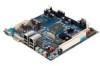
...System power management and temperature monitoring - Mini-ITX (6-layer) - 17 cm x 17 cm Note: This specification is disabled) - 1 x CF Type I connector (shared with fanless heatsink - Version 1.00 Up to change without prior notice. Fan speed detection - EPIA-M700-10E - Wake-on-LAN, Keyboard power... and unified video decoding acceleration - 1 x UltraDMA 133/100/66/33 pin connector - 2 x VIA VT6130 PCIe Gigabit LAN controller - Award BIOS - EPIA-M700-15 - CPU voltage monitoring - VIA VX800 Unified Digital Media IGP Chipset - 1 x DDR2 533/667 SODIMM slot - non-condensing) -...
...System power management and temperature monitoring - Mini-ITX (6-layer) - 17 cm x 17 cm Note: This specification is disabled) - 1 x CF Type I connector (shared with fanless heatsink - Version 1.00 Up to change without prior notice. Fan speed detection - EPIA-M700-10E - Wake-on-LAN, Keyboard power... and unified video decoding acceleration - 1 x UltraDMA 133/100/66/33 pin connector - 2 x VIA VT6130 PCIe Gigabit LAN controller - Award BIOS - EPIA-M700-15 - CPU voltage monitoring - VIA VX800 Unified Digital Media IGP Chipset - 1 x DDR2 533/667 SODIMM slot - non-condensing) -...

Operation Guide
Page 11
...5V 4.993 2.029 Main Board 5VSB 5.112 0.135 Main Board +12V 11.986 0.084 Total Power Consumption Watts 3.407 10.131 0.690 1.007 15.235 D. Power DVD 7.0 Measured Voltage Main Board +3.3V 3.312 Main Board +5V 4.979 Main Board 5VSB 5.100 Main Board +12V 11.983 Measure... May 23, 2008 - 9 - The following tables are a comprehensive breakdown of the voltage, amp and wattage values while running common system applications. VIA EPIA-M700-15 A. Media Player Measured Voltage Main Board +3.3V 3.320 Main Board +5V 4.984 Main Board 5VSB 5.107 Main Board +12V 11.992 Measure Amp...
...5V 4.993 2.029 Main Board 5VSB 5.112 0.135 Main Board +12V 11.986 0.084 Total Power Consumption Watts 3.407 10.131 0.690 1.007 15.235 D. Power DVD 7.0 Measured Voltage Main Board +3.3V 3.312 Main Board +5V 4.979 Main Board 5VSB 5.100 Main Board +12V 11.983 Measure... May 23, 2008 - 9 - The following tables are a comprehensive breakdown of the voltage, amp and wattage values while running common system applications. VIA EPIA-M700-15 A. Media Player Measured Voltage Main Board +3.3V 3.320 Main Board +5V 4.984 Main Board 5VSB 5.107 Main Board +12V 11.992 Measure Amp...
Operation Guide
Page 15
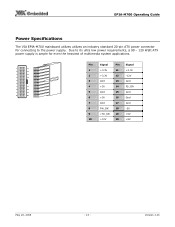
EPIA-M700 Operating Guide Power Specifications The VIA EPIA-M700 mainboard utilizes utilizes an industry standard 20-pin ATX power connector for connecting to its ultra low power requirements, a 90 - 120 Watt ATX ... 2 12 3 13 4 14 5 6 7 17 8 18 9 19 10 20 Pin Signal Pin Signal 1 +3.3V 11 +3.3V 2 +3.3V 12 -12V 3 Gnd 13 Gnd 4 +5V 14 PS_ON 5 Gnd 15 Gnd 6 +5V 16 Gnd 7 Gnd 17 Gnd 8 PW_OK 18 -5V 9 +5V_SB 19 +5V 10 +12V 20 +5V May 23, 2008 - 13 - Version 1.00 Due to...
EPIA-M700 Operating Guide Power Specifications The VIA EPIA-M700 mainboard utilizes utilizes an industry standard 20-pin ATX power connector for connecting to its ultra low power requirements, a 90 - 120 Watt ATX ... 2 12 3 13 4 14 5 6 7 17 8 18 9 19 10 20 Pin Signal Pin Signal 1 +3.3V 11 +3.3V 2 +3.3V 12 -12V 3 Gnd 13 Gnd 4 +5V 14 PS_ON 5 Gnd 15 Gnd 6 +5V 16 Gnd 7 Gnd 17 Gnd 8 PW_OK 18 -5V 9 +5V_SB 19 +5V 10 +12V 20 +5V May 23, 2008 - 13 - Version 1.00 Due to...
Operation Guide
Page 17
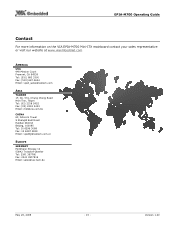
EPIA-M700 Operating Guide Contact For more information on the VIA EPIA-M700 Mini-ITX mainboard contact your sales representative or visit our website at www.viaembedded.com AMERICA USA 940 Mission Court Fremont, CA 94539 Tel: (510) 683 3300 ... Email: [email protected] ASIA TAIWAN 1F, No. 531, Chung Cheng Road Hsin Tien, Taipei Tel: (02) 2218 5452 Fax: (02) 2218 5453 Email: mkt@via.com.tw CHINA 6F, DAscom Tower 9 Shangdi East Road Haidian District Beijing, 100085 Tel: 10 6296 3088 Fax: 10 6297 2929 Email: [email protected]...
EPIA-M700 Operating Guide Contact For more information on the VIA EPIA-M700 Mini-ITX mainboard contact your sales representative or visit our website at www.viaembedded.com AMERICA USA 940 Mission Court Fremont, CA 94539 Tel: (510) 683 3300 ... Email: [email protected] ASIA TAIWAN 1F, No. 531, Chung Cheng Road Hsin Tien, Taipei Tel: (02) 2218 5452 Fax: (02) 2218 5453 Email: mkt@via.com.tw CHINA 6F, DAscom Tower 9 Shangdi East Road Haidian District Beijing, 100085 Tel: 10 6296 3088 Fax: 10 6297 2929 Email: [email protected]...
User Manual
Page 2
..., transcribed, stored in a retrieval system, or translated into any language, in this document. Copyright Copyright © 2008 VIA Technologies Incorporated. FCC-B Radio Frequency Interference Statement This equipment has been tested and found to provide reasonable protection against harmful interference...is granted, implied or otherwise, under any patent infringements that may cause harmful interference to part 15 of such change at his personal expense. VIA Technologies makes no responsibility for a class B digital device, pursuant to radio communications. This equipment...
..., transcribed, stored in a retrieval system, or translated into any language, in this document. Copyright Copyright © 2008 VIA Technologies Incorporated. FCC-B Radio Frequency Interference Statement This equipment has been tested and found to provide reasonable protection against harmful interference...is granted, implied or otherwise, under any patent infringements that may cause harmful interference to part 15 of such change at his personal expense. VIA Technologies makes no responsibility for a class B digital device, pursuant to radio communications. This equipment...
User Manual
Page 4
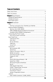
...: USB_2/1 13 KB/MS Connector 13 Front Panel Audio: F_Audio 14 Digital I/O: DIO ...14 MFX...14 Serial IrDA Infrared Module: SIR 15 Serial Port: COM2 15 SPI (Serial Peripheral Interface 15 Buzzer ...15 DVP (Digital Video Port 16 S/PDIF: Digital Audio Connector 16 VIP (Video Input Port 17 Front Panel: F_Panel 17 System Temperature...
...: USB_2/1 13 KB/MS Connector 13 Front Panel Audio: F_Audio 14 Digital I/O: DIO ...14 MFX...14 Serial IrDA Infrared Module: SIR 15 Serial Port: COM2 15 SPI (Serial Peripheral Interface 15 Buzzer ...15 DVP (Digital Video Port 16 S/PDIF: Digital Audio Connector 16 VIP (Video Input Port 17 Front Panel: F_Panel 17 System Temperature...
User Manual
Page 18
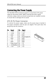
EPIA-M700 User's Manual Connecting the Power Supply The VIA EPIA-M700 mainboard supports a conventional ATX power supply for the power system. Before inserting the power supply connector, always make sure the power plug is ... the plug firmly into the connector. Pin Signal Pin Signal 1 +3.3V 11 +3.3V 2 +3.3V 12 -12V 3 GND 13 GND 4 +5V 14 Power Supply On 5 GND 15 GND 6 +5V 16 GND 7 GND 17 GND 8 Power Good 18 -5V 9 +5V Standby 19 +5V 10 +12V 20 +5V 10 ATX 20-Pin Power Connector...
EPIA-M700 User's Manual Connecting the Power Supply The VIA EPIA-M700 mainboard supports a conventional ATX power supply for the power system. Before inserting the power supply connector, always make sure the power plug is ... the plug firmly into the connector. Pin Signal Pin Signal 1 +3.3V 11 +3.3V 2 +3.3V 12 -12V 3 GND 13 GND 4 +5V 14 Power Supply On 5 GND 15 GND 6 +5V 16 GND 7 GND 17 GND 8 Power Good 18 -5V 9 +5V Standby 19 +5V 10 +12V 20 +5V 10 ATX 20-Pin Power Connector...
User Manual
Page 20
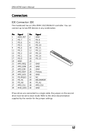
Pin Signal Pin 1 #IDE_RST 2 3 PD_7 4 5 PD_6 6 7 PD_5 8 9 PD_4 10 11 PD_3 12 13 PD_2 14 15 PD_1 16 17 PD_0 18 19 GND 20 21 #PD_REQ 22 23 #PD_IOW 24 25 #PD_IOR 26 27 #PD_RDY 28 29 #PD_ACK 30 31 PD_IRQ15 ...
Pin Signal Pin 1 #IDE_RST 2 3 PD_7 4 5 PD_6 6 7 PD_5 8 9 PD_4 10 11 PD_3 12 13 PD_2 14 15 PD_1 16 17 PD_0 18 19 GND 20 21 #PD_REQ 22 23 #PD_IOW 24 25 #PD_IOR 26 27 #PD_RDY 28 29 #PD_ACK 30 31 PD_IRQ15 ...
User Manual
Page 23
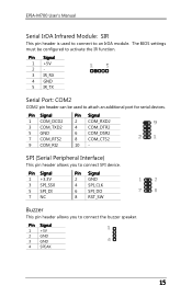
... Signal 1 +5V 2 3 IR_RX 4 GND 5 IR_TX Serial Port: COM2 COM2 pin header can be configured to activate the IR function. Pin Signal 1 +5V 2 GND 3 GND 4 SPEAK 15 SPI (Serial Peripheral Interface) This pin header allows you to connect the buzzer speaker. Pin Signal 1 +3.3V 3 SPI_SS0 5 SPI_DI 7 NC Pin Signal 2 GND 4 SPI_CLK 6 SPI_DO...
... Signal 1 +5V 2 3 IR_RX 4 GND 5 IR_TX Serial Port: COM2 COM2 pin header can be configured to activate the IR function. Pin Signal 1 +5V 2 GND 3 GND 4 SPEAK 15 SPI (Serial Peripheral Interface) This pin header allows you to connect the buzzer speaker. Pin Signal 1 +3.3V 3 SPI_SS0 5 SPI_DI 7 NC Pin Signal 2 GND 4 SPI_CLK 6 SPI_DO...

User Manual
Page 24
... devices, which allows you to an external Dolby Digital Decoder. Pin Signal Pin 1 +12V 2 3 +12V 4 5 +12V 6 7 GND 8 9 +3.3V 10 11 +3.3V 12 13 DVP1_D0 14 15 DVP1_D2 16 17 DVP1_D4 18 19 GND 20 21 DVP1_D6 22 23 DVP1_D8 24 25 DVP1_D10 26 27 GND 28 29 DVP1_D12 30 31 DVP1_D14...
... devices, which allows you to an external Dolby Digital Decoder. Pin Signal Pin 1 +12V 2 3 +12V 4 5 +12V 6 7 GND 8 9 +3.3V 10 11 +3.3V 12 13 DVP1_D0 14 15 DVP1_D2 16 17 DVP1_D4 18 19 GND 20 21 DVP1_D6 22 23 DVP1_D8 24 25 DVP1_D10 26 27 GND 28 29 DVP1_D12 30 31 DVP1_D14...
User Manual
Page 25
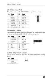
.../transport stream video. Pin Signal Pin Signal 1 GND 2 VCP_D0 3 VCP_D7 4 VCP_D4 5 VCP_D6 6 VCP_D5 7 VCP_HS 8 VCP_D2 9 VCP_D1 10 VCP_D3 11 VCP_VS 12 VCP_CLK 13 DVP1_SPD 14 - 15 DVP1_SPCLK 16 GND Front Panel: F_Panel The F_PANEL pin header allows you to connect the power switch, reset switch, power LED, sleep LED, HDD LED...
.../transport stream video. Pin Signal Pin Signal 1 GND 2 VCP_D0 3 VCP_D7 4 VCP_D4 5 VCP_D6 6 VCP_D5 7 VCP_HS 8 VCP_D2 9 VCP_D1 10 VCP_D3 11 VCP_VS 12 VCP_CLK 13 DVP1_SPD 14 - 15 DVP1_SPCLK 16 GND Front Panel: F_Panel The F_PANEL pin header allows you to connect the power switch, reset switch, power LED, sleep LED, HDD LED...

User Manual
Page 42
...'s Manual Typematic Rate (Chars/Sec) This item sets the rate (characters/second) at which the system retrieves a signal from the depressed key. Settings: [6, 8, 10, 12, 15, 20, 24, 30] Typematic Delay (Msec) This item sets the delay between, when the key was first pressed and when the system begins to shadow...
...'s Manual Typematic Rate (Chars/Sec) This item sets the rate (characters/second) at which the system retrieves a signal from the depressed key. Settings: [6, 8, 10, 12, 15, 20, 24, 30] Typematic Delay (Msec) This item sets the delay between, when the key was first pressed and when the system begins to shadow...
User Manual
Page 56
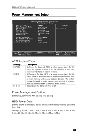
... is a low power state. Settings: [Disable, 1 Min, 2 Min, 3 Min, 4 Min, 5 Min, 6 Min, 7 Min, 8 Min, 9 Min, 10 Min, 11 Min, 12 Min, 13 Min, 14 Min, 15 Min] 48 The system context is saved to select S1 or S3. EPIA-M700 User's Manual Power Management Setup ACPI Suspend Type Settings S1(POS...
... is a low power state. Settings: [Disable, 1 Min, 2 Min, 3 Min, 4 Min, 5 Min, 6 Min, 7 Min, 8 Min, 9 Min, 10 Min, 11 Min, 12 Min, 13 Min, 14 Min, 15 Min] 48 The system context is saved to select S1 or S3. EPIA-M700 User's Manual Power Management Setup ACPI Suspend Type Settings S1(POS...