User Manual
Page 1
EPIA-M700 User's Manual Version 1.03 September 25, 2008
EPIA-M700 User's Manual Version 1.03 September 25, 2008
User Manual
Page 2
... document. Notice 1 The changes or modifications not expressly approved by any means, electronic, mechanical, magnetic, optical, chemical, manual or otherwise without obligation to comply with the emission limits. Trademarks All trademarks are designed to provide reasonable protection against harmful ...document and to the products described in accordance with the limits for compliance could void the user's authority to cause harmful interference, in a commercial environment. However, VIA Technologies assumes no warranties, implied or otherwise, in regard to this equipment in a ...
... document. Notice 1 The changes or modifications not expressly approved by any means, electronic, mechanical, magnetic, optical, chemical, manual or otherwise without obligation to comply with the emission limits. Trademarks All trademarks are designed to provide reasonable protection against harmful ...document and to the products described in accordance with the limits for compliance could void the user's authority to cause harmful interference, in a commercial environment. However, VIA Technologies assumes no warranties, implied or otherwise, in regard to this equipment in a ...

User Manual
Page 3
Keep this User's Manual for future reference. Place the power cord in a storage temperature above 60oC (140oF). The equipment has not worked well or you cannot get the equipment .... The equipment has dropped and damaged. If any add-on the enclosure are for this equipment on a reliable flat surface before connecting the equipment to User's Manual. The equipment has been exposed to force open the battery. iii Make sure the voltage of the power source and adjust properly 110/220V before...
Keep this User's Manual for future reference. Place the power cord in a storage temperature above 60oC (140oF). The equipment has not worked well or you cannot get the equipment .... The equipment has dropped and damaged. If any add-on the enclosure are for this equipment on a reliable flat surface before connecting the equipment to User's Manual. The equipment has been exposed to force open the battery. iii Make sure the voltage of the power source and adjust properly 110/220V before...
User Manual
Page 9
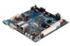
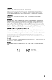
... creation of an exciting new generation of small, ergonomic, innovative and affordable embedded systems. Through a high level of integration, the Mini-ITX occupy 66% of the size of FlexATX mainboard form factor. EPIA-M700 User's Manual CHHAAPPTTEERR 1 SPECIFICATIONS The ultra-compact and highly integrated VIA EPIA-M700 uses the MiniITX mainboard form-factor developed by...
... creation of an exciting new generation of small, ergonomic, innovative and affordable embedded systems. Through a high level of integration, the Mini-ITX occupy 66% of the size of FlexATX mainboard form factor. EPIA-M700 User's Manual CHHAAPPTTEERR 1 SPECIFICATIONS The ultra-compact and highly integrated VIA EPIA-M700 uses the MiniITX mainboard form-factor developed by...

User Manual
Page 10
EPIA-M700 User's Manual Mainboard Specifications CPU • VIA C7 1.0GHz / 1.5GHz NanoBGA2 processor Chipset • VIA VX800 advanced all-in-one system processor Graphics • Integrated VIA Chrome9™ HC DX9 3D/2D Graphics and Unified Video Decoding Accelerator Audio • VIA VT1708B High Definition ...up to 2 GB) Expansion Slot • 1 x PCI slot IDE • 1 x UltraDMA 133/100/66/33 pin header LAN • 2 x VIA VT6130 PCIe Gigabit Ethernet Controllers Onboard I/O Connectors • 1 x USB pin header for 2 additional USB 2.0 ports • 1 x Digital video input pin header...
EPIA-M700 User's Manual Mainboard Specifications CPU • VIA C7 1.0GHz / 1.5GHz NanoBGA2 processor Chipset • VIA VX800 advanced all-in-one system processor Graphics • Integrated VIA Chrome9™ HC DX9 3D/2D Graphics and Unified Video Decoding Accelerator Audio • VIA VT1708B High Definition ...up to 2 GB) Expansion Slot • 1 x PCI slot IDE • 1 x UltraDMA 133/100/66/33 pin header LAN • 2 x VIA VT6130 PCIe Gigabit Ethernet Controllers Onboard I/O Connectors • 1 x USB pin header for 2 additional USB 2.0 ports • 1 x Digital video input pin header...
User Manual
Page 11
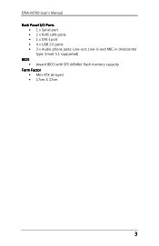
EPIA-M700 User's Manual Back Panel I/O Ports • 1 x Serial port • 2 x RJ45 LAN ports • 1 x DVI-I port • 4 x USB 2.0 ports • 3 x Audio phone jacks: Line-out, Line-in and MIC-in (Horizontal type, Smart 5.1 supported) BIOS • Award BIOS with SPI 4/8Mbit flash memory capacity Form Factor • Mini-ITX (6-layer) • 17cm X 17cm 3
EPIA-M700 User's Manual Back Panel I/O Ports • 1 x Serial port • 2 x RJ45 LAN ports • 1 x DVI-I port • 4 x USB 2.0 ports • 3 x Audio phone jacks: Line-out, Line-in and MIC-in (Horizontal type, Smart 5.1 supported) BIOS • Award BIOS with SPI 4/8Mbit flash memory capacity Form Factor • Mini-ITX (6-layer) • 17cm X 17cm 3

User Manual
Page 15
Electrostatic discharge (ESD) can damage some components. 7 EPIA-M700 User's Manual CHHAAPPTTEERR 2 INSTALLATION This chapter provides you with information about hardware installation procedures. It is recommended to use a grounded wrist strap before handling computer components.
Electrostatic discharge (ESD) can damage some components. 7 EPIA-M700 User's Manual CHHAAPPTTEERR 2 INSTALLATION This chapter provides you with information about hardware installation procedures. It is recommended to use a grounded wrist strap before handling computer components.

User Manual
Page 16
... wire) should always be connected to GND. EPIA-M700 User's Manual CPU The VIA EPIA-M700 mainboard is Ground and should be connected to the +12V. To provide sufficient cooling, VIA C7 1.5 GHz processor requires a heatsink with a standard VIA C7 1.5 GHz / 1.0 GHz NanoBGA2 processor. The black... wire is packaged with fan while VIA C7 1.0 GHz requires only a heatsink. 120 240 1.8V 1 121 ...
... wire) should always be connected to GND. EPIA-M700 User's Manual CPU The VIA EPIA-M700 mainboard is Ground and should be connected to the +12V. To provide sufficient cooling, VIA C7 1.5 GHz processor requires a heatsink with a standard VIA C7 1.5 GHz / 1.0 GHz NanoBGA2 processor. The black... wire is packaged with fan while VIA C7 1.0 GHz requires only a heatsink. 120 240 1.8V 1 121 ...
User Manual
Page 17
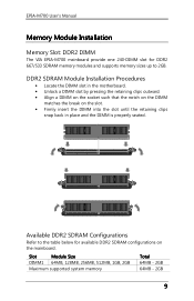
... - 2GB 64MB - 2GB 9 EPIA-M700 User's Manual Memory Module Installation Memory Slot: DDR2 DIMM The VIA EPIA-M700 mainboard provide one 240-DIMM slot for available DDR2 SDRAM configurations on the slot. • Firmly insert the DIMM into the slot until the retaining clips snap back in the motherboard. • Unlock a DIMM slot by...
... - 2GB 64MB - 2GB 9 EPIA-M700 User's Manual Memory Module Installation Memory Slot: DDR2 DIMM The VIA EPIA-M700 mainboard provide one 240-DIMM slot for available DDR2 SDRAM configurations on the slot. • Firmly insert the DIMM into the slot until the retaining clips snap back in the motherboard. • Unlock a DIMM slot by...
User Manual
Page 18
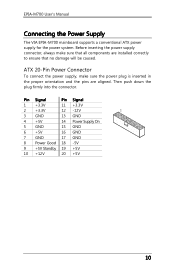
... the pins are installed correctly to ensure that all components are aligned. Then push down the plug firmly into the connector. EPIA-M700 User's Manual Connecting the Power Supply The VIA EPIA-M700 mainboard supports a conventional ATX power supply for the power system. Pin Signal Pin Signal 1 +3.3V 11 +3.3V 2 +3.3V 12 -12V...
... the pins are installed correctly to ensure that all components are aligned. Then push down the plug firmly into the connector. EPIA-M700 User's Manual Connecting the Power Supply The VIA EPIA-M700 mainboard supports a conventional ATX power supply for the power system. Pin Signal Pin Signal 1 +3.3V 11 +3.3V 2 +3.3V 12 -12V...

User Manual
Page 19
... an external audio device such as a CD player, tape player, etc. USB Ports Four standard USB 2.0 ports are provided on the back panel. EPIA-M700 User's Manual Back Panel Ports The back panel has the following ports: Gigabit Ethernet RJ-45 Ports Line-In Com Port DVI-I port allows you to connect...
... an external audio device such as a CD player, tape player, etc. USB Ports Four standard USB 2.0 ports are provided on the back panel. EPIA-M700 User's Manual Back Panel Ports The back panel has the following ports: Gigabit Ethernet RJ-45 Ports Line-In Com Port DVI-I port allows you to connect...
User Manual
Page 20
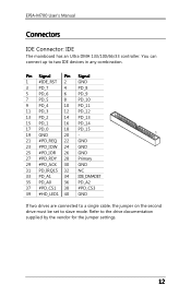
EPIA-M700 User's Manual Connectors IDE Connector: IDE The mainboard has an Ultra DMA 133/100/66/33 controller. Refer to two IDE devices in any combination. You can ...
EPIA-M700 User's Manual Connectors IDE Connector: IDE The mainboard has an Ultra DMA 133/100/66/33 controller. Refer to two IDE devices in any combination. You can ...

User Manual
Page 21
... peripherals such as USB HDD, digital cameras, MP3 players, printers, modem and the like. Please short pin 3&5, pin 4&6, pin 7&9 and pin 8&10. 13 EPIA-M700 User's Manual SATA Ports These next generation connectors support the thin SATA cables for primary internal storage devices. Therefore mainboard can be used to two additional USB...
... peripherals such as USB HDD, digital cameras, MP3 players, printers, modem and the like. Please short pin 3&5, pin 4&6, pin 7&9 and pin 8&10. 13 EPIA-M700 User's Manual SATA Ports These next generation connectors support the thin SATA cables for primary internal storage devices. Therefore mainboard can be used to two additional USB...

User Manual
Page 22
... Signal 2 AGND 4 FNT_DET 6 LINE_R_R 8 10 LINE_R_L 12 +12V 14 AGND Note: If you to the rear audio ports. EPIA-M700 User's Manual Front Panel Audio: F_Audio This pin header is for the VIA front panel audio cable that allow convenient connection and control of audio devices. Otherwise, the Line-Out connector on cards...
... Signal 2 AGND 4 FNT_DET 6 LINE_R_R 8 10 LINE_R_L 12 +12V 14 AGND Note: If you to the rear audio ports. EPIA-M700 User's Manual Front Panel Audio: F_Audio This pin header is for the VIA front panel audio cable that allow convenient connection and control of audio devices. Otherwise, the Line-Out connector on cards...
User Manual
Page 23
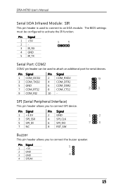
EPIA-M700 User's Manual Serial IrDA Infrared Module: SIR This pin header is used to connect SPI device. SPI (Serial Peripheral Interface) This pin header allows you to connect ...
EPIA-M700 User's Manual Serial IrDA Infrared Module: SIR This pin header is used to connect SPI device. SPI (Serial Peripheral Interface) This pin header allows you to connect ...

User Manual
Page 24
The feature is for HDMI and DVI are currently available respectively. Pin Signal 1 +5V 2 SPDIF_OUT 3 GND 16 EPIA-M700 User's Manual DVP (Digital Video Port) This female connector works the interface to display devices, which allows you to an external Dolby Digital Decoder. Daughter cards for ...
The feature is for HDMI and DVI are currently available respectively. Pin Signal 1 +5V 2 SPDIF_OUT 3 GND 16 EPIA-M700 User's Manual DVP (Digital Video Port) This female connector works the interface to display devices, which allows you to an external Dolby Digital Decoder. Daughter cards for ...
User Manual
Page 25
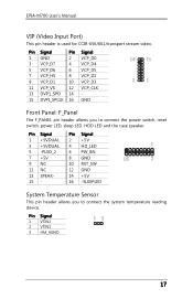
... 10 RST_SW 12 GND 14 +5V 16 -SLEEPLED System Temperature Sensor This pin header allows you to connect the system temperature reading device. EPIA-M700 User's Manual VIP (Video Input Port) This pin header is used for CCIR-656/601/transport stream video. Pin Signal Pin Signal 1 GND 2 VCP_D0 3 VCP_D7 4 VCP_D4 5 VCP_D6...
... 10 RST_SW 12 GND 14 +5V 16 -SLEEPLED System Temperature Sensor This pin header allows you to connect the system temperature reading device. EPIA-M700 User's Manual VIP (Video Input Port) This pin header is used for CCIR-656/601/transport stream video. Pin Signal Pin Signal 1 GND 2 VCP_D0 3 VCP_D7 4 VCP_D4 5 VCP_D6...

User Manual
Page 26
... of the CF connector. Removing the cap will damage the mainboard. Avoid clearing the CMOS while the system is to pins 2 and 3 afterwards. EPIA-M700 User's Manual Jumpers The mainboard provides jumpers for the CF Connector: V_CF_SEL This VCC selector jumper is on CLEAR_CMOS jumper default position. Setting 123 +3.3V +5V +3.3V...
... of the CF connector. Removing the cap will damage the mainboard. Avoid clearing the CMOS while the system is to pins 2 and 3 afterwards. EPIA-M700 User's Manual Jumpers The mainboard provides jumpers for the CF Connector: V_CF_SEL This VCC selector jumper is on CLEAR_CMOS jumper default position. Setting 123 +3.3V +5V +3.3V...

User Manual
Page 27
... the PCI bus INT A# ~ INT D# pins as follows: PCI Slot Order 1 INT B# Order 2 INT C# Order 3 INT D# Order 4 INT A# Compact Flash Type I adapter. 19 EPIA-M700 User's Manual Slots Peripheral Component Interconnect: PCI The PCI slot allows you to connect to the microprocessor. Read the documentation for the expansion card if any changes...
... the PCI bus INT A# ~ INT D# pins as follows: PCI Slot Order 1 INT B# Order 2 INT C# Order 3 INT D# Order 4 INT A# Compact Flash Type I adapter. 19 EPIA-M700 User's Manual Slots Peripheral Component Interconnect: PCI The PCI slot allows you to connect to the microprocessor. Read the documentation for the expansion card if any changes...

User Manual
Page 28
EPIA-M700 User's Manual This page is intentionally left blank. 20
EPIA-M700 User's Manual This page is intentionally left blank. 20