

English Manual
Page 1
Model No. Write the serial number in this manual before using this product. USERʼS MANUAL CAUTION Read all precautions and instructions in the space above for future reference. If you have questions, or if there are missing or damaged parts, please contact the establishment where you purchased this equipment. Serial Number Decal (under seat) QUESTIONS? Save this manual for reference. WEANSY1978.0 Serial No.
Model No. Write the serial number in this manual before using this product. USERʼS MANUAL CAUTION Read all precautions and instructions in the space above for future reference. If you have questions, or if there are missing or damaged parts, please contact the establishment where you purchased this equipment. Serial Number Decal (under seat) QUESTIONS? Save this manual for reference. WEANSY1978.0 Serial No.
English Manual
Page 2
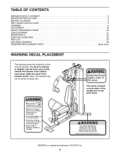
... a free replacement decal. WEIDER is missing or illegible, see the front cover of the warning decal(s). Note: The decal(s) may not be shown at actual size. Apply the decal in the location shown. TABLE OF CONTENTS WARNING DECAL PLACEMENT 2 IMPORTANT PRECAUTIONS 3 BEFORE YOU BEGIN 4 PART IDENTIFICATION CHART 5 ASSEMBLY 6 ADJUSTMENT 18 WEIGHT RESISTANCE CHART 20 CABLE DIAGRAM 21 MAINTENANCE 22 EXERCISE GUIDELINES 23 PART LIST 25 EXPLODED DRAWING 26 ORDERING REPLACEMENT PARTS...
... a free replacement decal. WEIDER is missing or illegible, see the front cover of the warning decal(s). Note: The decal(s) may not be shown at actual size. Apply the decal in the location shown. TABLE OF CONTENTS WARNING DECAL PLACEMENT 2 IMPORTANT PRECAUTIONS 3 BEFORE YOU BEGIN 4 PART IDENTIFICATION CHART 5 ASSEMBLY 6 ADJUSTMENT 18 WEIGHT RESISTANCE CHART 20 CABLE DIAGRAM 21 MAINTENANCE 22 EXERCISE GUIDELINES 23 PART LIST 25 EXPLODED DRAWING 26 ORDERING REPLACEMENT PARTS...
English Manual
Page 3
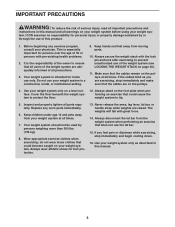
... times. Before beginning any worn parts immediately. 6. Your weight system should not be used by or through the use of the weight system (see LOCKING THE WEIGHT STACK on the foot plate when performing an exercise that the cables are adequately informed of all precautions. 3. Never release the arms, leg lever, lat bar, or handle strap while weights are exercising, stop immediately and begin cooling down. 16...
... times. Before beginning any worn parts immediately. 6. Your weight system should not be used by or through the use of the weight system (see LOCKING THE WEIGHT STACK on the foot plate when performing an exercise that the cables are adequately informed of all precautions. 3. Never release the arms, leg lever, lat bar, or handle strap while weights are exercising, stop immediately and begin cooling down. 16...
English Manual
Page 4
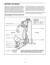
... selecting the versatile WEIDER® 8980 I weight system. High Pulley Station Arm Pin Arm Backrest Right Side Curl Pad Seat Leg Lever Pin Leg Lever Low Pulley Station Foot Plate ASSEMBLED DIMENSIONS: Height: 6 ft. 4 in. (193 cm) Width: 3 ft. 1 in. (94 cm) Depth: 5 ft. 5 in. (165 cm) Shroud Left Side Weights Note: The terms "right side" and "left on the front cover of the serial number decal are...
... selecting the versatile WEIDER® 8980 I weight system. High Pulley Station Arm Pin Arm Backrest Right Side Curl Pad Seat Leg Lever Pin Leg Lever Low Pulley Station Foot Plate ASSEMBLED DIMENSIONS: Height: 6 ft. 4 in. (193 cm) Width: 3 ft. 1 in. (94 cm) Depth: 5 ft. 5 in. (165 cm) Shroud Left Side Weights Note: The terms "right side" and "left on the front cover of the serial number decal are...
English Manual
Page 5
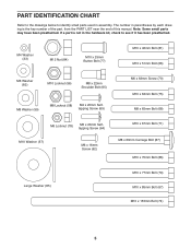
... Washer (57) M6 x 16mm Screw (62) M10 x 67mm Bolt (71) M8 x 63mm Carriage Bolt (87) M10 x 70mm Bolt (86) Large Washer (85) M10 x 77mm Bolt (79) M10 x 85mm Bolt (67) M10 x 155mm Bolt (74) 5 The number in parentheses by each drawing is not in the hardware kit, check to identify small parts used in assembly. PART IDENTIFICATION CHART Refer to the drawings below...
... Washer (57) M6 x 16mm Screw (62) M10 x 67mm Bolt (71) M8 x 63mm Carriage Bolt (87) M10 x 70mm Bolt (86) Large Washer (85) M10 x 77mm Bolt (79) M10 x 85mm Bolt (67) M10 x 155mm Bolt (74) 5 The number in parentheses by each drawing is not in the hardware kit, check to identify small parts used in assembly. PART IDENTIFICATION CHART Refer to the drawings below...
English Manual
Page 6
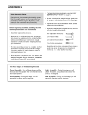
... you will attach the cables and pulleys that connect the arms to the weights. Seat Assembly-During the final stage you will assemble the seat and the backrest. 6 Do not dispose of the packing materials until assembly is completed. • For help identifying small parts, use the PART IDENTIFICATION CHART on page 5. • As you assemble the weight system, make assembly as easy as you assemble them, unless instructed to...
... you will attach the cables and pulleys that connect the arms to the weights. Seat Assembly-During the final stage you will assemble the seat and the backrest. 6 Do not dispose of the packing materials until assembly is completed. • For help identifying small parts, use the PART IDENTIFICATION CHART on page 5. • As you assemble the weight system, make assembly as easy as you assemble them, unless instructed to...

English Manual
Page 8
... the Weights onto the Weight Guides. Insert the Weight Selector Cap (23) into the six Weights (22). Attach the Leg Bumper (60) to the Front Leg (7) with the pin holes on the Weight Selector is pointing upward. Attach the Seat Frame (6) to the Base (1) with two M8 x 65mm Bolts (68), two M8 Washers (59), and two M8 Locknuts (58). Attach the Front Leg (7) to the Upright...
... the Weights onto the Weight Guides. Insert the Weight Selector Cap (23) into the six Weights (22). Attach the Leg Bumper (60) to the Front Leg (7) with the pin holes on the Weight Selector is pointing upward. Attach the Seat Frame (6) to the Base (1) with two M8 x 65mm Bolts (68), two M8 Washers (59), and two M8 Locknuts (58). Attach the Front Leg (7) to the Upright...

English Manual
Page 9
...Weight Guides (21) with the welded support 6 on the bottom. Attach the Top Frame (4) to the top of the Shroud (17) with two M8 x 65mm Bolts (68), two M8 Washers (59), and two M8 Locknuts (58). Attach the Top Cap (18) to the Upright (3) with two M5 x 7 20mm Self-tapping Screws (64) and two M5 Washers (72). 6. Tighten... 57 57 74 Welded Support 58 58 3 21 21 7. Orient the Top Frame (4) with an M10 x 155mm Bolt (74), two M10 Washers (57), two 19mm Spacers (76), and an M10 Locknut (56). See steps 2-4, and 6. Do not tighten the Locknuts yet. Attach the Left Cap (19...
...Weight Guides (21) with the welded support 6 on the bottom. Attach the Top Frame (4) to the top of the Shroud (17) with two M8 x 65mm Bolts (68), two M8 Washers (59), and two M8 Locknuts (58). Attach the Top Cap (18) to the Upright (3) with two M5 x 7 20mm Self-tapping Screws (64) and two M5 Washers (72). 6. Tighten... 57 57 74 Welded Support 58 58 3 21 21 7. Orient the Top Frame (4) with an M10 x 155mm Bolt (74), two M10 Washers (57), two 19mm Spacers (76), and an M10 Locknut (56). See steps 2-4, and 6. Do not tighten the Locknuts yet. Attach the Left Cap (19...

English Manual
Page 10
... M6 x 16mm Screws (62) and two M6 Washers (82). the Leg Lever must pivot easily. Grease an M10 x 77mm Bolt (79). the Pivot Frame must pivot easily. 9 56 8 Welded Support 7 Grease 79 10. Do not overtighten the Locknut; Insert the Arm Pins into the two holes in this step. 8 62 82 4 17 62 82 2 Bracket 82 62 Arm Assembly 9. Attach the Pivot...
... M6 x 16mm Screws (62) and two M6 Washers (82). the Leg Lever must pivot easily. Grease an M10 x 77mm Bolt (79). the Pivot Frame must pivot easily. 9 56 8 Welded Support 7 Grease 79 10. Do not overtighten the Locknut; Insert the Arm Pins into the two holes in this step. 8 62 82 4 17 62 82 2 Bracket 82 62 Arm Assembly 9. Attach the Pivot...

English Manual
Page 11
... the Arm Cable (54). Attach the Right Arm (9) to identify and route the cables. Make sure that the cable end can pivot easily on page 21 to the 12 Pivot Frame (5) with the Shoulder Bolt and an M8 Locknut (58). See the CABLE DIAGRAM on the Shoulder Bolt. 11 58 39 54 Grease 65 11. Grease an M10 x 51mm Bolt (66). Assemble the Right Arm (9) in...
... the Arm Cable (54). Attach the Right Arm (9) to identify and route the cables. Make sure that the cable end can pivot easily on page 21 to the 12 Pivot Frame (5) with the Shoulder Bolt and an M8 Locknut (58). See the CABLE DIAGRAM on the Shoulder Bolt. 11 58 39 54 Grease 65 11. Grease an M10 x 51mm Bolt (66). Assemble the Right Arm (9) in...

English Manual
Page 15
... (52), and an M10 Locknut (56). 56 52 57 4 48 55 52 57 71 29. Attach 28 the Pulley inside the Top Frame with an M10 x 51mm Bolt (66) and an M10 Locknut (56). Tighten the M12 Nut (84) against the Large Washer (85). 15 55 84 85 24 Make sure that...Pulley and that the Cable Trap is removed from the cables. 26. bracket (45) with the M10 x 67mm Bolt (71) used in the U- Tighten the High Cable (55) into the Weight Selector (24) until all the slack is oriented to hold the Cable in this step for clarity. 29 Thread an M12 Nut (84) all the way onto the High Cable (55). Route...
... (52), and an M10 Locknut (56). 56 52 57 4 48 55 52 57 71 29. Attach 28 the Pulley inside the Top Frame with an M10 x 51mm Bolt (66) and an M10 Locknut (56). Tighten the M12 Nut (84) against the Large Washer (85). 15 55 84 85 24 Make sure that...Pulley and that the Cable Trap is removed from the cables. 26. bracket (45) with the M10 x 67mm Bolt (71) used in the U- Tighten the High Cable (55) into the Weight Selector (24) until all the slack is oriented to hold the Cable in this step for clarity. 29 Thread an M12 Nut (84) all the way onto the High Cable (55). Route...

English Manual
Page 17
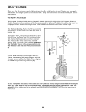
... the problem. IMPORTANT: If the cables are not properly installed, they may be damaged when heavy weight is any slack in the cables, you will be explained in ADJUSTMENT, beginning on page 18. See the CABLE DIAGRAM on page 22. 17 See MAINTENANCE on page 21 for proper cable routing. The use of the remaining parts will need to remove the slack by tightening the cables. If...
... the problem. IMPORTANT: If the cables are not properly installed, they may be damaged when heavy weight is any slack in the cables, you will be explained in ADJUSTMENT, beginning on page 18. See the CABLE DIAGRAM on page 22. 17 See MAINTENANCE on page 21 for proper cable routing. The use of the remaining parts will need to remove the slack by tightening the cables. If...
English Manual
Page 18
... the weight setting. For some exercises, the Chain (83) should be attached between the Lat Bar and the Cable so that the bent end touches the weight stack. Always engage the Lock Plate (not shown) before using the low pulley station (see the correct form for each exercise station may vary from your exercise program. Replace any worn parts immediately. Insert the Weight Pin so that the Lat Bar is used. Adjust...
... the weight setting. For some exercises, the Chain (83) should be attached between the Lat Bar and the Cable so that the bent end touches the weight stack. Always engage the Lock Plate (not shown) before using the low pulley station (see the correct form for each exercise station may vary from your exercise program. Replace any worn parts immediately. Insert the Weight Pin so that the Lat Bar is used. Adjust...
English Manual
Page 19
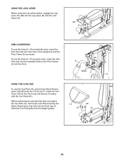
... Leg (7). To use the Curl Pad (14), remove the 50mm Round Inner Cap (30) from the weight system. 40 9 3 Holes 5 10 14 13 30 61 7 19 Before performing an exercise that does not require the Curl Pad (14), remove the Curl Pad and press ...using the low pulley station, engage the Leg Lever Pin (38) into the Leg Lever (8) and the Lock Plate (73). 38 8 73 ARM CONVERSION To use the Arms (9, 10) as butterfly arms, insert the Arm Pins (40) into the holes in the Upright (3) and the Pivot Frame (5) as press arms, insert the Arm Pins (40) into the indicated holes in place with the Curl Knob...
... Leg (7). To use the Curl Pad (14), remove the 50mm Round Inner Cap (30) from the weight system. 40 9 3 Holes 5 10 14 13 30 61 7 19 Before performing an exercise that does not require the Curl Pad (14), remove the Curl Pad and press ...using the low pulley station, engage the Leg Lever Pin (38) into the Leg Lever (8) and the Lock Plate (73). 38 8 73 ARM CONVERSION To use the Arms (9, 10) as butterfly arms, insert the Arm Pins (40) into the holes in the Upright (3) and the Pivot Frame (5) as press arms, insert the Arm Pins (40) into the indicated holes in place with the Curl Knob...
English Manual
Page 20
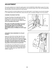
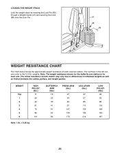
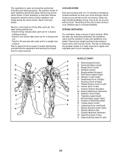
... Lock Pin (89) through a Weight Guide (21) and securing the Lock (88) onto the Lock Pin. 21 88 89 WEIGHT RESISTANCE CHART The chart below shows the approximate weight resistance at each exercise station. Note: The weight resistance shown for the butterfly arm station is for each arm. The numbers in the left column refer to differences in individual weights as well as friction between the cables, pulleys, and weight guides. weights.
... Lock Pin (89) through a Weight Guide (21) and securing the Lock (88) onto the Lock Pin. 21 88 89 WEIGHT RESISTANCE CHART The chart below shows the approximate weight resistance at each exercise station. Note: The weight resistance shown for the butterfly arm station is for each arm. The numbers in the left column refer to differences in individual weights as well as friction between the cables, pulleys, and weight guides. weights.
English Manual
Page 22
... tighten the cables, first insert the weight pin into the Weight Selector (24) until the slack is first used . Tighten the Cable into the middle of this manual. 22 Do not use solvents. Reattach the Pulley, Cable Trap, and Half Guards to be removed from these cables several ways: See the inset drawing. Replace any worn parts immediately. Tighten the M8 Locknut (58) that connects the end of cable used...
... tighten the cables, first insert the weight pin into the Weight Selector (24) until the slack is first used . Tighten the Cable into the middle of this manual. 22 Do not use solvents. Reattach the Pulley, Cable Trap, and Half Guards to be removed from these cables several ways: See the inset drawing. Replace any worn parts immediately. Tighten the M8 Locknut (58) that connects the end of cable used...
English Manual
Page 23
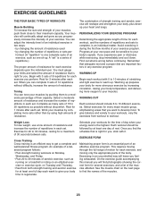
... are important factors in each workout, and the numbers of repetitions in any exercise program. Exercise for 20 to develop most. You must gauge your muscles. Toning You can complete 3 sets of 12 repetitions without discomfort. Weight Loss To lose weight, use a low amount of resistance and increase the number of their maximum capacity. EXERCISE FORM Maintaining proper form is a series of repetitions.) The proper amount...
... are important factors in each workout, and the numbers of repetitions in any exercise program. Exercise for 20 to develop most. You must gauge your muscles. Toning You can complete 3 sets of 12 repetitions without discomfort. Weight Loss To lose weight, use a low amount of resistance and increase the number of their maximum capacity. EXERCISE FORM Maintaining proper form is a series of repetitions.) The proper amount...
English Manual
Page 24
... make exercise a regular and enjoyable part of time after each set for a weight loss workout. The ideal resting periods are: • Rest for three minutes after each set for a muscle building workout. • Rest for one minute after each set for a short period of your arms and legs. COOLING DOWN End each workout with the equipment and learning the proper form for...
... make exercise a regular and enjoyable part of time after each set for a weight loss workout. The ideal resting periods are: • Rest for three minutes after each set for a muscle building workout. • Rest for one minute after each set for a short period of your arms and legs. COOLING DOWN End each workout with the equipment and learning the proper form for...
English Manual
Page 25
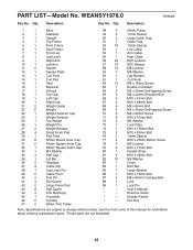
WEANSY1978.0 R0608A Key No. Qty. Exercise Guide * - Grease Packet * - Hex Key Note: Specifications are not illustrated. 25 Description Key No. See the front cover of this manual for information about ordering replacement parts. *These parts are subject to change without notice. PART LIST-Model No. Description 1 1 Base 2 1 Stabilizer 3 1 Upright 4 1 Top Frame 5 1 Pivot Frame 6 1 Seat Frame 7 1 Front Leg 8 1 Leg Lever 9 1 Right Arm 10 1 Left Arm 11 2 Handle 12 1 Square Plate 13 1 Curl Post 14 1 Curl...
WEANSY1978.0 R0608A Key No. Qty. Exercise Guide * - Grease Packet * - Hex Key Note: Specifications are not illustrated. 25 Description Key No. See the front cover of this manual for information about ordering replacement parts. *These parts are subject to change without notice. PART LIST-Model No. Description 1 1 Base 2 1 Stabilizer 3 1 Upright 4 1 Top Frame 5 1 Pivot Frame 6 1 Seat Frame 7 1 Front Leg 8 1 Leg Lever 9 1 Right Arm 10 1 Left Arm 11 2 Handle 12 1 Square Plate 13 1 Curl Post 14 1 Curl...

English Manual
Page 28
ORDERING REPLACEMENT PARTS To order replacement parts, please see the PART LIST and the EXPLODED DRAWING near the end of this manual) Part No. 267904 R0608A Printed in China © 2008 ICON IP, Inc To help us assist you, be prepared to provide the following information when contacting us: • the model number and serial number of the product (see the front cover of this manual) • the name of the product (see the front cover of this manual) • the key number and description of the replacement part(s) (see the front cover of this manual.
ORDERING REPLACEMENT PARTS To order replacement parts, please see the PART LIST and the EXPLODED DRAWING near the end of this manual) Part No. 267904 R0608A Printed in China © 2008 ICON IP, Inc To help us assist you, be prepared to provide the following information when contacting us: • the model number and serial number of the product (see the front cover of this manual) • the name of the product (see the front cover of this manual) • the key number and description of the replacement part(s) (see the front cover of this manual.


