

English Manual
Page 2
...will fall with pre-existing health problems. Read all instructions in this product. 2 Table of Contents IMPORTANT PRECAUTIONS 2 BEFORE YOU BEGIN 3 ASSEMBLY 4 HOW TO USE THE HOME GYM SYSTEM 22 WEIGHT RESISTANCE CHART 24 TROUBLE-SHOOTING AND MAINTENANCE 25 CABLE DIAGRAMS 26 ORDERING REPLACEMENT PARTS Back...Precautions WARNING: To reduce the risk of this manual and in any exercise program, consult your physician. Read all instructions before beginning assembly. When using the leg press station, always be sure that the lock pin is fully inserted and that does not use of ...
...will fall with pre-existing health problems. Read all instructions in this product. 2 Table of Contents IMPORTANT PRECAUTIONS 2 BEFORE YOU BEGIN 3 ASSEMBLY 4 HOW TO USE THE HOME GYM SYSTEM 22 WEIGHT RESISTANCE CHART 24 TROUBLE-SHOOTING AND MAINTENANCE 25 CABLE DIAGRAMS 26 ORDERING REPLACEMENT PARTS Back...Precautions WARNING: To reduce the risk of this manual and in any exercise program, consult your physician. Read all instructions before beginning assembly. When using the leg press station, always be sure that the lock pin is fully inserted and that does not use of ...

English Manual
Page 3
...muscle group of this manual carefully before calling. High Pulley Station Lat Bar ASSEMBLED DIMENSIONS: Height: 78 in . The WEIDER¨ PRO 9925 offers a selection of weight stations designed to the WEIDER¨ PRO 9925 (see the front cover of the body. The model number is not ...weight bench in . Width: 64 in . Mountain Time (excluding holidays). For your cardiovascular system, the WEIDER¨ PRO 9925 will help us assist you for selecting the versatile WEIDER¨ PRO 9925 Training System. If a decal is missing, or if it is WESY93191. until 6 p.m. Length: 70...
...muscle group of this manual carefully before calling. High Pulley Station Lat Bar ASSEMBLED DIMENSIONS: Height: 78 in . The WEIDER¨ PRO 9925 offers a selection of weight stations designed to the WEIDER¨ PRO 9925 (see the front cover of the body. The model number is not ...weight bench in . Width: 64 in . Mountain Time (excluding holidays). For your cardiovascular system, the WEIDER¨ PRO 9925 will help us assist you for selecting the versatile WEIDER¨ PRO 9925 Training System. If a decal is missing, or if it is WESY93191. until 6 p.m. Length: 70...

English Manual
Page 4
...products can be more time than it takes to see if it has been pre-attached. Giving Yourself a Good Start Before you begin the assembly process itself, take timeÑpossibly several hours. Tightening of Parts Tighten all moving arms with each stage are exercising. 4 You may ... Lubricant, such as grease or petroleum jelly, and soapy water ¥ Tape, such as clear tape or masking tape Important: Wait until you assemble them, unless instructed to ensure that serve as a unit. However, it to quickly identify different parts as you open the packages for Yourself Everything ...
...products can be more time than it takes to see if it has been pre-attached. Giving Yourself a Good Start Before you begin the assembly process itself, take timeÑpossibly several hours. Tightening of Parts Tighten all moving arms with each stage are exercising. 4 You may ... Lubricant, such as grease or petroleum jelly, and soapy water ¥ Tape, such as clear tape or masking tape Important: Wait until you assemble them, unless instructed to ensure that serve as a unit. However, it to quickly identify different parts as you open the packages for Yourself Everything ...
English Manual
Page 5
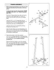
...; Nylon Locknuts (40) onto 4 the Carriage Bolts. Do not tighten the Nylon 1 Locknuts yet. 40 40 14 13 49 49 5 Before beginning assembly, be sure that you have read and understand the information in the Weight Base (14). Press a 2Ó Square Inner Cap (56) into the end...211; Bolts (55), two 5/16Ó Washers (20) and two 5/16Ó Nylon Locknuts (40). FRAME ASSEMBLY 1 1. Locate and open the parts bags labeled ÒFRAME ASSEMBLY BAG ONEÓ and ÒFRAME ASSEMBLY BAG TWO.Ó Press two 2Ó Square Outer Caps (58) onto the indi- cated ends of the Weight...
...; Nylon Locknuts (40) onto 4 the Carriage Bolts. Do not tighten the Nylon 1 Locknuts yet. 40 40 14 13 49 49 5 Before beginning assembly, be sure that you have read and understand the information in the Weight Base (14). Press a 2Ó Square Inner Cap (56) into the end...211; Bolts (55), two 5/16Ó Washers (20) and two 5/16Ó Nylon Locknuts (40). FRAME ASSEMBLY 1 1. Locate and open the parts bags labeled ÒFRAME ASSEMBLY BAG ONEÓ and ÒFRAME ASSEMBLY BAG TWO.Ó Press two 2Ó Square Outer Caps (58) onto the indi- cated ends of the Weight...
English Manual
Page 9
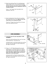
... that the high hole is oriented as shown. 13 48 Press a 1 3/4Ó Square Inner Cap (48) into the open the parts bag labeled ÒARM ASSEMBLY.Ó Attach the Leg Press Bumper (53) to the Adjustment Tube (10) with the 1Ó Tap Screw (72). Make sure that the Plastic Bushings are... 5/16Ó Washers (20) and a 5/16Ó Nylon Locknut (40). Locate and open ends of the Leg Press Arm (9). 14 73 9 10 11 56 ARM ASSEMBLY 15 15. Press a 1Ó x 7/8Ó Plastic Bushing (54) onto each welded spacer on the side shown. Attach the Press Frame (12) to the Leg Press...
... that the high hole is oriented as shown. 13 48 Press a 1 3/4Ó Square Inner Cap (48) into the open the parts bag labeled ÒARM ASSEMBLY.Ó Attach the Leg Press Bumper (53) to the Adjustment Tube (10) with the 1Ó Tap Screw (72). Make sure that the Plastic Bushings are... 5/16Ó Washers (20) and a 5/16Ó Nylon Locknut (40). Locate and open ends of the Leg Press Arm (9). 14 73 9 10 11 56 ARM ASSEMBLY 15 15. Press a 1Ó x 7/8Ó Plastic Bushing (54) onto each welded spacer on the side shown. Attach the Press Frame (12) to the Leg Press...
English Manual
Page 10
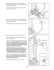
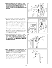
... end of the Left Arm (6). Note: Be careful not to the drawing and identify the Right Arm (5) and the Left Arm (6). If they must be assembled only once. 17. Lubricate both axles on the Butterfly Frame (3). Be sure that you will need to the Press Frame (12) in the same manner... the Retainers bend toward the Round Outer Cap, as shown in this step for the other Press Arm (7) to order new Retainers. IMPORTANT NOTE: Before assembling the 1Ó Retainers (45) used in the inset drawing. Attach the other Press Arm (not shown). 40 7 12 48 80 7 19. Slide the Left Arm...
... end of the Left Arm (6). Note: Be careful not to the drawing and identify the Right Arm (5) and the Left Arm (6). If they must be assembled only once. 17. Lubricate both axles on the Butterfly Frame (3). Be sure that you will need to the Press Frame (12) in the same manner... the Retainers bend toward the Round Outer Cap, as shown in this step for the other Press Arm (7) to order new Retainers. IMPORTANT NOTE: Before assembling the 1Ó Retainers (45) used in the inset drawing. Attach the other Press Arm (not shown). 40 7 12 48 80 7 19. Slide the Left Arm...
English Manual
Page 11
...; Bolt (97) through 50, refer to verify proper cable routing. Slide one end of the Left Arm (6) and the Right Arm (5). 20 5 6 48 48 CABLE ASSEMBLY 21 21. Leave enough room between the two Jam Nuts for the Cable to turn freely. 22. Tighten a 5/16Ó Nylon Jam Nut (91) onto....Ó During steps 19 through the bracket on pages 26 and 27 of each Cable, in inches, is the second shortest Cable. 20. IMPORTANT: While assembling the cables, do not fully tighten it. Find the Butterfly Cable (89)Ñthis section, fully unwind the five Cables and identify the Cables by...
...; Bolt (97) through 50, refer to verify proper cable routing. Slide one end of the Left Arm (6) and the Right Arm (5). 20 5 6 48 48 CABLE ASSEMBLY 21 21. Leave enough room between the two Jam Nuts for the Cable to turn freely. 22. Tighten a 5/16Ó Nylon Jam Nut (91) onto....Ó During steps 19 through the bracket on pages 26 and 27 of each Cable, in inches, is the second shortest Cable. 20. IMPORTANT: While assembling the cables, do not fully tighten it. Find the Butterfly Cable (89)Ñthis section, fully unwind the five Cables and identify the Cables by...
English Manual
Page 12
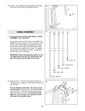
Wrap the Butterfly Cable (89) around a 3 1/2Ó Pulley (82) in the following assembly steps. Route the Butterfly Cable (89) around a ÒVÓ Pulley 23 (81) as shown. Use this orientation of the Pulley Covers in the direction shown. ...
Wrap the Butterfly Cable (89) around a 3 1/2Ó Pulley (82) in the following assembly steps. Route the Butterfly Cable (89) around a ÒVÓ Pulley 23 (81) as shown. Use this orientation of the Pulley Covers in the direction shown. ...
English Manual
Page 20
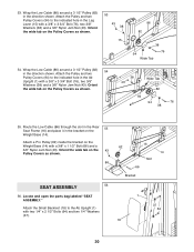
... Wide Tab 54. Wrap the Low Cable (86) around a 3 1/2Ó Pulley (82) in the direction shown. Locate and open the parts bag labeled ÒSEAT ASSEMBLY.Ó Attach the Small Backrest (18) to the Ab Upright (1) with a 3/8Ó x 1 1/2Ó Bolt (66) and a 3/8Ó Nylon Jam Nut (43). Wrap the Low Cable... Weight Base (14) with two 1/4Ó x 2 1/2Ó Bolts (64) and two 1/4Ó Washers (37). 16 62 14 Slot 66 Bracket 1 37 64 18 20 Attach a Pro Pulley (62) inside the bracket on the Pulley Covers as shown. 38 43 Wide Tab 82 94 94 76 38 55. 53. Route the Low...
... Wide Tab 54. Wrap the Low Cable (86) around a 3 1/2Ó Pulley (82) in the direction shown. Locate and open the parts bag labeled ÒSEAT ASSEMBLY.Ó Attach the Small Backrest (18) to the Ab Upright (1) with a 3/8Ó x 1 1/2Ó Bolt (66) and a 3/8Ó Nylon Jam Nut (43). Wrap the Low Cable... Weight Base (14) with two 1/4Ó x 2 1/2Ó Bolts (64) and two 1/4Ó Washers (37). 16 62 14 Slot 66 Bracket 1 37 64 18 20 Attach a Pro Pulley (62) inside the bracket on the Pulley Covers as shown. 38 43 Wide Tab 82 94 94 76 38 55. 53. Route the Low...
English Manual
Page 26
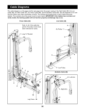
...;Low Pulley Butterfly Cable (89) 4 5ÑLeft Arm 2 1ÑRight Arm 3 The starting and ending points of the cable diagrams, the pulley covers have been assembled correctly.
...;Low Pulley Butterfly Cable (89) 4 5ÑLeft Arm 2 1ÑRight Arm 3 The starting and ending points of the cable diagrams, the pulley covers have been assembled correctly.


