

English Manual
Page 2
...Never release the press arm, butterfly arms, leg lever, leg press plate, lat bar, ab strap, or nylon strap while weights are raised. The weights will fall with pre-existing health problems. Read all parts often. ICON assumes no responsibility for home use of this manual. It... worn parts immediately. 5. Table of Contents IMPORTANT PRECAUTIONS 2 BEFORE YOU BEGIN 3 ASSEMBLY 4 HOW TO USE THE HOME GYM SYSTEM 22 WEIGHT RESISTANCE CHART 24 TROUBLE-SHOOTING AND MAINTENANCE 25 CABLE DIAGRAMS 26 ORDERING REPLACEMENT PARTS Back Cover LIMITED WARRANTY Back Cover Note: A PART IDENTIFICATION ...
...Never release the press arm, butterfly arms, leg lever, leg press plate, lat bar, ab strap, or nylon strap while weights are raised. The weights will fall with pre-existing health problems. Read all parts often. ICON assumes no responsibility for home use of this manual. It... worn parts immediately. 5. Table of Contents IMPORTANT PRECAUTIONS 2 BEFORE YOU BEGIN 3 ASSEMBLY 4 HOW TO USE THE HOME GYM SYSTEM 22 WEIGHT RESISTANCE CHART 24 TROUBLE-SHOOTING AND MAINTENANCE 25 CABLE DIAGRAMS 26 ORDERING REPLACEMENT PARTS Back Cover LIMITED WARRANTY Back Cover Note: A PART IDENTIFICATION ...

English Manual
Page 3
... not legible, please call our Before reading further, please review the drawing below and familiarize yourself with the parts that are labeled. The WEIDER¨ PRO 9925 offers a selection of weight stations designed to tone your body, build dramatic muscle size and strength, or improve your benefit, read this manual). Customer Service Department toll...
... not legible, please call our Before reading further, please review the drawing below and familiarize yourself with the parts that are labeled. The WEIDER¨ PRO 9925 offers a selection of weight stations designed to tone your body, build dramatic muscle size and strength, or improve your benefit, read this manual). Customer Service Department toll...

English Manual
Page 4
... masking tape Important: Wait until assembly is not in the parts bag, check to open the parts bag labeled for each other and with the weights. Do not dispose of the packing materials until you begin each stage are exercising. 4 Some assembly steps require two people. The seat and all moving...
... masking tape Important: Wait until assembly is not in the parts bag, check to open the parts bag labeled for each other and with the weights. Do not dispose of the packing materials until you begin each stage are exercising. 4 Some assembly steps require two people. The seat and all moving...
English Manual
Page 5
...up through the indicated holes in the box above. Slide the Leg Press Upright (4) onto the indicated 5/16Ó x 2 1/2Ó Carriage Bolts (49) in the Weight Base (14). Slide the Ab Upright (1) onto the indicated 2 5/16Ó x 2 1/2Ó Carriage Bolts (49) in the Press Base (13). Do not...Ó Nylon Locknuts (40) onto 4 the Carriage Bolts. Insert two 5/16Ó x 2 1/4Ó Carriage Bolts (61) up through the other holes in the Weight Base. 56 Insert four 5/16Ó x 2 1/2Ó Carriage Bolts (49) up through the Press Base (13). Hand tighten two 5/16Ó Nylon Locknuts (...
...up through the indicated holes in the box above. Slide the Leg Press Upright (4) onto the indicated 5/16Ó x 2 1/2Ó Carriage Bolts (49) in the Weight Base (14). Slide the Ab Upright (1) onto the indicated 2 5/16Ó x 2 1/2Ó Carriage Bolts (49) in the Press Base (13). Do not...Ó Nylon Locknuts (40) onto 4 the Carriage Bolts. Insert two 5/16Ó x 2 1/4Ó Carriage Bolts (61) up through the other holes in the Weight Base. 56 Insert four 5/16Ó x 2 1/2Ó Carriage Bolts (49) up through the Press Base (13). Hand tighten two 5/16Ó Nylon Locknuts (...
English Manual
Page 6
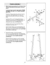
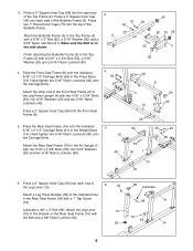
... Caps (70) into each side of the Butterfly Frame. Slide the Front Seat Frame (8) onto the indicated 5/16Ó x 2 1/2Ó Carriage Bolts (49) in the Weight Base (14). Hand tighten two 5/16Ó Nylon Locknuts (40) onto the Carriage Bolts. 3. Press a 2Ó Square Inner Cap (56) into the top of the...
... Caps (70) into each side of the Butterfly Frame. Slide the Front Seat Frame (8) onto the indicated 5/16Ó x 2 1/2Ó Carriage Bolts (49) in the Weight Base (14). Hand tighten two 5/16Ó Nylon Locknuts (40) onto the Carriage Bolts. 3. Press a 2Ó Square Inner Cap (56) into the top of the...

English Manual
Page 7
... in the pin grooves in the same manner. 23 23 40 8. 7. Attach the other Weight Guides (23) in the upper Weights. 25 26 90 90 Pin Grooves 7 Slide eight Weights (90) onto each set of the Weight Guides with a 5/16Ó x 6Ó Bolt (67), two 1/2Ó x ...3/4Ó Spacers (69), and a 5/16Ó Nylon Locknut (40). Attach the lower ends of Weight Guides (23). Insert a Weight Tube (25) into each of Weights (90). Slide a Weight Bumper (27) onto each Weight 9 Tube (25). Press a Weight Tube Bumper (26) into each stack of the brack- 7 ets on the...
... in the pin grooves in the same manner. 23 23 40 8. 7. Attach the other Weight Guides (23) in the upper Weights. 25 26 90 90 Pin Grooves 7 Slide eight Weights (90) onto each set of the Weight Guides with a 5/16Ó x 6Ó Bolt (67), two 1/2Ó x ...3/4Ó Spacers (69), and a 5/16Ó Nylon Locknut (40). Attach the lower ends of Weight Guides (23). Insert a Weight Tube (25) into each of Weights (90). Slide a Weight Bumper (27) onto each Weight 9 Tube (25). Press a Weight Tube Bumper (26) into each stack of the brack- 7 ets on the...

English Manual
Page 8
...211; x 2 3/4Ó Bolts (55), two 5/16Ó Washers (20) and two 5/16Ó Nylon Locknuts (40). Attach the upper ends of the other set of Weight Guides (23) in the same manner. Attach the Top Frame (2) to the Leg Press Upright (4) with a 5/16Ó x 6Ó Bolt (67), two 1/2Ó ...x 3/4Ó Spacers (69) and a 5/16Ó Nylon Locknut (40). Attach the upper ends of one set of Weight Guides (23) to the Top Frame (2) with two 5/16Ó x 2 3/4Ó Bolts (55), a 20 3 Support Plate (95) and two 5/16Ó Nylon Locknuts 2 (40...
...211; x 2 3/4Ó Bolts (55), two 5/16Ó Washers (20) and two 5/16Ó Nylon Locknuts (40). Attach the upper ends of the other set of Weight Guides (23) in the same manner. Attach the Top Frame (2) to the Leg Press Upright (4) with a 5/16Ó x 6Ó Bolt (67), two 1/2Ó ...x 3/4Ó Spacers (69) and a 5/16Ó Nylon Locknut (40). Attach the upper ends of one set of Weight Guides (23) to the Top Frame (2) with two 5/16Ó x 2 3/4Ó Bolts (55), a 20 3 Support Plate (95) and two 5/16Ó Nylon Locknuts 2 (40...
English Manual
Page 13
... with a 3/8Ó x 2Ó Bolt (50) and a 3/8Ó Nylon Locknut (42). Thread a 1/2Ó Plain Nut (83) onto the end of the Weight Tube (25). Place a 3/8Ó x 1 1/4Ó Weight Spacer (32) and a 1/2Ó Washer (68) on the Pulley Covers as shown. Attach a 3 1/2Ó Pulley (82) and two Pulley Covers 28 (94)... to the Top Frame (2) with the Top Weight (24) slightly to pivot. 91 92 87 28. Slide one end of the Weight Tube (25) until the Weight Spacer (32) touches the Weight Tube. Leave enough room between the two Jam Nuts for the Cable to ...
... with a 3/8Ó x 2Ó Bolt (50) and a 3/8Ó Nylon Locknut (42). Thread a 1/2Ó Plain Nut (83) onto the end of the Weight Tube (25). Place a 3/8Ó x 1 1/4Ó Weight Spacer (32) and a 1/2Ó Washer (68) on the Pulley Covers as shown. Attach a 3 1/2Ó Pulley (82) and two Pulley Covers 28 (94)... to the Top Frame (2) with the Top Weight (24) slightly to pivot. 91 92 87 28. Slide one end of the Weight Tube (25) until the Weight Spacer (32) touches the Weight Tube. Leave enough room between the two Jam Nuts for the Cable to ...
English Manual
Page 18
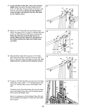
...; x 3 3/4Ó Bolt (76), two 3/8Ó Washers (38) and a 3/8Ó Nylon Jam Nut (43). Make sure that the Cable is necessary to lift the Weight Tube (25) with the Top Weight (24) slightly to the Ab Upright (1) with two holes should be down 47. Locate one of the preassembled pairs of the... Weight Tube (25) until the Weight Spacer (10) touches the Weight Tube. Attach the Pulley and two Pulley Covers (94) to thread the High Cable (85) in the direction shown. Thread a ...
...; x 3 3/4Ó Bolt (76), two 3/8Ó Washers (38) and a 3/8Ó Nylon Jam Nut (43). Make sure that the Cable is necessary to lift the Weight Tube (25) with the Top Weight (24) slightly to the Ab Upright (1) with two holes should be down 47. Locate one of the preassembled pairs of the... Weight Tube (25) until the Weight Spacer (10) touches the Weight Tube. Attach the Pulley and two Pulley Covers (94) to thread the High Cable (85) in the direction shown. Thread a ...
English Manual
Page 20
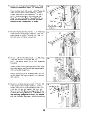
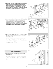
Attach a Pro Pulley (62) inside the bracket on the Weight Base (14) with two 1/4Ó x 2 1/2Ó Bolts (64) and two 1/4Ó Washers (37). 16 62 14 Slot 66 Bracket 1 37 64 18 20 Wrap the ... tab on the Pulley Covers as shown. 53 43 38 15 86 82 38 76 94 Wide Tab 54. Orient the wide tab on the Weight Base (14). 53. Attach the Pulley and two Pulley Covers (94) to the indicated hole in the Ab Upright (1) with a 3/8Ó x 3 3/4Ó Bolt (76), two...
Attach a Pro Pulley (62) inside the bracket on the Weight Base (14) with two 1/4Ó x 2 1/2Ó Bolts (64) and two 1/4Ó Washers (37). 16 62 14 Slot 66 Bracket 1 37 64 18 20 Wrap the ... tab on the Pulley Covers as shown. 53 43 38 15 86 82 38 76 94 Wide Tab 54. Orient the wide tab on the Weight Base (14). 53. Attach the Pulley and two Pulley Covers (94) to the indicated hole in the Ab Upright (1) with a 3/8Ó x 3 3/4Ó Bolt (76), two...

English Manual
Page 22
... over the pulleys. Make sure that the cables move smoothly, find and correct the problem. Attach the Curl Pad (77) to be damaged when heavy weight is any slack in HOW TO USE THE HOME GYM SYSTEM, beginning on page 25. 22 If there is used. Repeat this manual.
... over the pulleys. Make sure that the cables move smoothly, find and correct the problem. Attach the Curl Pad (77) to be damaged when heavy weight is any slack in HOW TO USE THE HOME GYM SYSTEM, beginning on page 25. 22 If there is used. Repeat this manual.

English Manual
Page 23
... and the holes in the Leg Press Arm (9) with two Cable Clips. Refer to the exercise poster accompanying this manual to be performed. Insert the Weight Pin until the bent end of the exercise will be adjusted. The Nylon Strap (96) can be reduced. For some exercises, the Chain (34)... the lat bar or nylon strap, make sure that the hook on page 24 to find the approximate amount of either weight stack, insert a Weight Pin (93) under the desired Weight (90). If there is any slack in the correct starting position for each exercise station may vary from the Adjustment Tube...
... and the holes in the Leg Press Arm (9) with two Cable Clips. Refer to the exercise poster accompanying this manual to be performed. Insert the Weight Pin until the bent end of the exercise will be adjusted. The Nylon Strap (96) can be reduced. For some exercises, the Chain (34)... the lat bar or nylon strap, make sure that the hook on page 24 to find the approximate amount of either weight stack, insert a Weight Pin (93) under the desired Weight (90). If there is any slack in the correct starting position for each exercise station may vary from the Adjustment Tube...

English Manual
Page 25
...210;UÓ Bracket (84). Remove the cable and re-install it. 86, 88 If the cables need to be tightened further, the 1/2Ó x 1 1/4Ó Weight Spacer (32) can stretch slightly when it may have become twisted. Remove the 3/8Ó Nylon Locknut (42) and the 3/8Ó x 2Ó Bolt (50) from... tightened in the end of this manual. 25 Do not overtighten the cables. Loosen the 1/2Ó Plain Nut (83) on the back cover of the Weight Tube (25). Remove the 3/8Ó x 2Ó Bolt (50) and the 3/8Ó Nylon Locknut (42) securing the lower 3 1/3Ó Pulley (82) and the...
...210;UÓ Bracket (84). Remove the cable and re-install it. 86, 88 If the cables need to be tightened further, the 1/2Ó x 1 1/4Ó Weight Spacer (32) can stretch slightly when it may have become twisted. Remove the 3/8Ó Nylon Locknut (42) and the 3/8Ó x 2Ó Bolt (50) from... tightened in the end of this manual. 25 Do not overtighten the cables. Loosen the 1/2Ó Plain Nut (83) on the back cover of the Weight Tube (25). Remove the 3/8Ó x 2Ó Bolt (50) and the 3/8Ó Nylon Locknut (42) securing the lower 3 1/3Ó Pulley (82) and the...
English Manual
Page 27
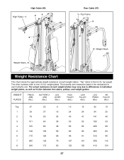
...1ÑTop Frame 3 2 3 4ÑWeight Stack Weight StackÑ5 Weight Resistance Chart This chart shows the approximate weight resistance at each weight station may vary due to differences in individual weight plates, as well as friction between the cables, pulleys, and weight guides. The other numbers refer to the... 12.5 lb. WEIGHT PLATES PRESS ARM (lbs.) ...
...1ÑTop Frame 3 2 3 4ÑWeight Stack Weight StackÑ5 Weight Resistance Chart This chart shows the approximate weight resistance at each weight station may vary due to differences in individual weight plates, as well as friction between the cables, pulleys, and weight guides. The other numbers refer to the... 12.5 lb. WEIGHT PLATES PRESS ARM (lbs.) ...

English Manual
Page 31
... Inner Cap 3/8Ó x 3 1/2Ó Bolt 2Ó Square Outer Cap 1/4Ó x 3/4Ó Bolt 1/4Ó x 2 1/2Ó Carriage Bolt 5/16Ó X 2 1/4Ó Carriage Bolt Pro Pulley 1/4Ó x 2 1/4Ó Bolt 1/4Ó x 2 1/2Ó Bolt 3/8Ó x 2 1/2Ó Bolt 3/8Ó x 1 1/2Ó Bolt 5/16Ó x 6Ó Bolt 1/2Ó...Backrest 5/16Ó Washer 5Ó Plastic Grip Butterfly Pad Weight Guide Top Weight Weight Tube Weight Tube Bumper Weight Bumper Pad Tube Foam Pad Leg Lever Spacer Pulley Plate 3/8Ó x 1 1/4Ó Weight Spacer Cable Clip Chain Ab Strap Lat Bar 1/4Ó Washer...
... Inner Cap 3/8Ó x 3 1/2Ó Bolt 2Ó Square Outer Cap 1/4Ó x 3/4Ó Bolt 1/4Ó x 2 1/2Ó Carriage Bolt 5/16Ó X 2 1/4Ó Carriage Bolt Pro Pulley 1/4Ó x 2 1/4Ó Bolt 1/4Ó x 2 1/2Ó Bolt 3/8Ó x 2 1/2Ó Bolt 3/8Ó x 1 1/2Ó Bolt 5/16Ó x 6Ó Bolt 1/2Ó...Backrest 5/16Ó Washer 5Ó Plastic Grip Butterfly Pad Weight Guide Top Weight Weight Tube Weight Tube Bumper Weight Bumper Pad Tube Foam Pad Leg Lever Spacer Pulley Plate 3/8Ó x 1 1/4Ó Weight Spacer Cable Clip Chain Ab Strap Lat Bar 1/4Ó Washer...


