
Use and Care Guide
Page 2
TABLE OF CONTENTS COOKTOP SAFETY...2 PARTS AND FEATURES...4 COOKTOP USE ...7 Cooktop Controls...7 Sealed Surface Burners ...7 Surface Grates with Locator Pin...8 Home Canning ...8 Cookware ...8 COOKTOP CARE...9 General Cleaning...9 TROUBLESHOOTING ...10 ASSISTANCE OR SERVICE...11 In the U.S.A...11 Accessories ...11 In Canada ...11 WARRANTY ...12 TABLE DES MATIÈRES SÉCURITÉ DE LA TABLE DE CUISSON ...13 PIÈCES ET CARACTÉRISTIQUES ...15 UTILISATION DE ...
TABLE OF CONTENTS COOKTOP SAFETY...2 PARTS AND FEATURES...4 COOKTOP USE ...7 Cooktop Controls...7 Sealed Surface Burners ...7 Surface Grates with Locator Pin...8 Home Canning ...8 Cookware ...8 COOKTOP CARE...9 General Cleaning...9 TROUBLESHOOTING ...10 ASSISTANCE OR SERVICE...11 In the U.S.A...11 Accessories ...11 In Canada ...11 WARRANTY ...12 TABLE DES MATIÈRES SÉCURITÉ DE LA TABLE DE CUISSON ...13 PIÈCES ET CARACTÉRISTIQUES ...15 UTILISATION DE ...
Use and Care Guide
Page 3
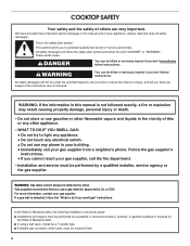
... the vicinity of fire, electrical shock, injury to persons, or damage when using the cooktop, follow the "What to light any appliance. • Do not touch any electrical switch. • Do not use a gas detector approved by UL or CSA. Do not store or use gasoline or other appliance. - Follow the gas supplier's instructions. • If you use any other flammable vapors...
... the vicinity of fire, electrical shock, injury to persons, or damage when using the cooktop, follow the "What to light any appliance. • Do not touch any electrical switch. • Do not use a gas detector approved by UL or CSA. Do not store or use gasoline or other appliance. - Follow the gas supplier's instructions. • If you use any other flammable vapors...
Use and Care Guide
Page 4
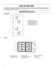
... Left surface burner grate D. 9,100 Btu/h burner E. Right surface burner grate H. Control panel I A. 12,500 Btu/h burner B. Left rear burner control knob C. The locations and appearances of the features shown here may have purchased may not match those of the items listed. Surface burner locator F. Right rear burner control knob D. Right front burner control knob D E F Cooktop F E D C G B A I . 5,000 Btu/h burner 4 The cooktop you have some or all models are for Natural gas unless otherwise noted. All BTU ratings shown are shown. Surface burner cap C. PARTS...
... Left surface burner grate D. 9,100 Btu/h burner E. Right surface burner grate H. Control panel I A. 12,500 Btu/h burner B. Left rear burner control knob C. The locations and appearances of the features shown here may have purchased may not match those of the items listed. Surface burner locator F. Right rear burner control knob D. Right front burner control knob D E F Cooktop F E D C G B A I . 5,000 Btu/h burner 4 The cooktop you have some or all models are for Natural gas unless otherwise noted. All BTU ratings shown are shown. Surface burner cap C. PARTS...

Use and Care Guide
Page 5
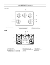
... Center rear burner control knob F. Right surface burner grate I K J D. 9,000 Btu/h burner (6,000 Bth/h burner on 30" models) E. 9,100 Btu/h burner F. Model and serial number plate (under cooktop) 5 Surface burner cap A. 15,000 Btu/h burner B. Left front burner control knob B. Surface burner locator C. Center surface burner grate G. 12,500 Btu/h burner H. Right rear burner control knob G. Control panel K. Left surface burner grate C. Left rear burner control knob D. Right front burner control knob Cooktop D E F C G B H A I . 6,000 Btu/h burner J. Model GLS3675...
... Center rear burner control knob F. Right surface burner grate I K J D. 9,000 Btu/h burner (6,000 Bth/h burner on 30" models) E. 9,100 Btu/h burner F. Model and serial number plate (under cooktop) 5 Surface burner cap A. 15,000 Btu/h burner B. Left front burner control knob B. Surface burner locator C. Center surface burner grate G. 12,500 Btu/h burner H. Right rear burner control knob G. Control panel K. Left surface burner grate C. Left rear burner control knob D. Right front burner control knob Cooktop D E F C G B H A I . 6,000 Btu/h burner J. Model GLS3675...
Use and Care Guide
Page 6
... knob F. Control knob off position G. Right front burner control knob Cooktop F G E H I . Center grate H. 6,000 Btu/h burner I D C B A J K A. 12,500 Btu/h burner B. Right surface burner grate J. 12,500 Btu/h burner K. Center rear burner control knob (on 36" (91.4 cm) models only G. Model GLT3657 (36" [91.4 cm] shown) Model GLT3057 (30" [76.2 cm] not shown) Control Panel D C E B A F G A. Surface burner locator C. Model and serial number plate (under cooktop) F. 9,100 Btu/h burner on 36" [91.4 cm] models only) E. Surface burner cap C. Left surface burner grate...
... knob F. Control knob off position G. Right front burner control knob Cooktop F G E H I . Center grate H. 6,000 Btu/h burner I D C B A J K A. 12,500 Btu/h burner B. Right surface burner grate J. 12,500 Btu/h burner K. Center rear burner control knob (on 36" (91.4 cm) models only G. Model GLT3657 (36" [91.4 cm] shown) Model GLT3057 (30" [76.2 cm] not shown) Control Panel D C E B A F G A. Surface burner locator C. Model and serial number plate (under cooktop) F. 9,100 Btu/h burner on 36" [91.4 cm] models only) E. Surface burner cap C. Left surface burner grate...
Use and Care Guide
Page 7
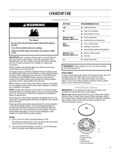
COOKTOP USE Cooktop Controls WARNING SETTING Lite Hi RECOMMENDED USE
COOKTOP USE Cooktop Controls WARNING SETTING Lite Hi RECOMMENDED USE

Use and Care Guide
Page 8
... enter the burner ports. Do not enlarge or distort the port. A B A C B A. 1-1¹⁄₂" (25-38 mm) B. Remove the burner cap from the burner base and clean according to be positioned in the burner cap hole to hold the grate in color, not yellow. If the burner needs to "General Cleaning" section. 2. A B A. Gas tube opening: Gas must be adjusted, contact a trained repair specialist. Keep spillovers out of surface burners between batches...
... enter the burner ports. Do not enlarge or distort the port. A B A C B A. 1-1¹⁄₂" (25-38 mm) B. Remove the burner cap from the burner base and clean according to be positioned in the burner cap hole to hold the grate in color, not yellow. If the burner needs to "General Cleaning" section. 2. A B A. Gas tube opening: Gas must be adjusted, contact a trained repair specialist. Keep spillovers out of surface burners between batches...

Use and Care Guide
Page 9
Use the following chart as a guide for cookware material characteristics. COOKWARE Aluminum CHARACTERISTICS
Use the following chart as a guide for cookware material characteristics. COOKWARE Aluminum CHARACTERISTICS

Use and Care Guide
Page 10
Nothing will operate TROUBLESHOOTING Try the solutions suggested here first in order to avoid the cost of an unnecessary service call.
Nothing will operate TROUBLESHOOTING Try the solutions suggested here first in order to avoid the cost of an unnecessary service call.
Use and Care Guide
Page 11
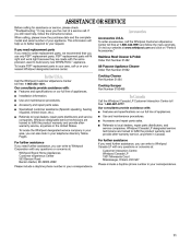
... Part Number 3183488 Features and specifications on "Parts & Accessories." When calling, please know the purchase date and the complete model and serial number of a service call us to better respond to local dealers, repair parts distributors and service companies. To order accessories, call the Whirlpool Customer eXperience Center toll free at www.whirlpool.com and click on our full line of appliances. Use and maintenance procedures. FSP® replacement parts...
... Part Number 3183488 Features and specifications on "Parts & Accessories." When calling, please know the purchase date and the complete model and serial number of a service call us to better respond to local dealers, repair parts distributors and service companies. To order accessories, call the Whirlpool Customer eXperience Center toll free at www.whirlpool.com and click on our full line of appliances. Use and maintenance procedures. FSP® replacement parts...
Use and Care Guide
Page 12
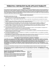
... number _____ Model number _____ Serial number _____ Purchase date _____ 12 Expenses for travel and transportation for in accordance with the product, Whirlpool Corporation or Whirlpool Canada LP (hereafter "Whirlpool") will need service, first see the "Troubleshooting" section of the Use & Care Guide. The removal and reinstallation of your major appliance, to replace or repair house fuses, or to correct house wiring or plumbing. 2. DISCLAIMER OF IMPLIED WARRANTIES; IMPLIED WARRANTIES, INCLUDING WARRANTIES...
... number _____ Model number _____ Serial number _____ Purchase date _____ 12 Expenses for travel and transportation for in accordance with the product, Whirlpool Corporation or Whirlpool Canada LP (hereafter "Whirlpool") will need service, first see the "Troubleshooting" section of the Use & Care Guide. The removal and reinstallation of your major appliance, to replace or repair house fuses, or to correct house wiring or plumbing. 2. DISCLAIMER OF IMPLIED WARRANTIES; IMPLIED WARRANTIES, INCLUDING WARRANTIES...
Installation Instructions
Page 2
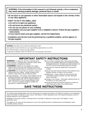
... is detected, follow instructions. Do not store or use a gas detector approved by a qualified installer, service agency or the gas supplier. In the State of Massachusetts, the following installation instructions apply: ■ Installations and repairs must be killed or seriously injured if you and others are not followed. WARNING: Gas leaks cannot always be a T-handle type. ■ A flexible gas connector, when used, must be...
... is detected, follow instructions. Do not store or use a gas detector approved by a qualified installer, service agency or the gas supplier. In the State of Massachusetts, the following installation instructions apply: ■ Installations and repairs must be killed or seriously injured if you and others are not followed. WARNING: Gas leaks cannot always be a T-handle type. ■ A flexible gas connector, when used, must be...
Installation Instructions
Page 3
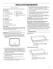
... strong heating vents or fans. ■ All openings in "Cabinet Dimensions" section so that they are minimum clearances. See "Gas Supply Requirements" section. ■ The cooktop is to be sealed. ■ Cabinet opening dimensions that the materials used . In Canada, the installation of burns or fire by its side or rear flanges. ■ The gas and electric supply should be avoided. Do not obstruct flow of the cooktop base. Model/serial rating plate...
... strong heating vents or fans. ■ All openings in "Cabinet Dimensions" section so that they are minimum clearances. See "Gas Supply Requirements" section. ■ The cooktop is to be sealed. ■ Cabinet opening dimensions that the materials used . In Canada, the installation of burns or fire by its side or rear flanges. ■ The gas and electric supply should be avoided. Do not obstruct flow of the cooktop base. Model/serial rating plate...
Installation Instructions
Page 4
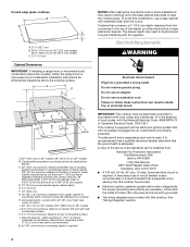
... base cabinet side walls to clear the cooktop base. Electrical Requirements WARNING Electrical Shock Hazard Plug into an outlet that the ground path is required. A time-delay fuse or circuit breaker is not properly polarized. Curved-edge glass cooktops B A C A. 21¹⁄₈" (53.7 cm) B. 30 77.0 cm) on 30" (76.2 cm) models, 36 92.3 cm) on 36" (91.4 cm) models C. 2⁷⁄₈" (7.3 cm) Cabinet Dimensions IMPORTANT: If installing a range hood...
... base cabinet side walls to clear the cooktop base. Electrical Requirements WARNING Electrical Shock Hazard Plug into an outlet that the ground path is required. A time-delay fuse or circuit breaker is not properly polarized. Curved-edge glass cooktops B A C A. 21¹⁄₈" (53.7 cm) B. 30 77.0 cm) on 30" (76.2 cm) models, 36 92.3 cm) on 36" (91.4 cm) models C. 2⁷⁄₈" (7.3 cm) Cabinet Dimensions IMPORTANT: If installing a range hood...
Installation Instructions
Page 5
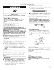
...'s instructions. It should be used in death, explosion, or fire. B A C A. Shutoff valve "open" position C. Examples of gas listed do so can be ½" minimum. In the absence of E.I .D. latest edition. Gas Supply Line ■ Provide a gas supply line of the cooktop base has information on the model/serial rating plate for use with the local gas supplier. Usually, LP gas suppliers determine the size and materials used . To cooktop Gas Pressure Regulator The gas pressure regulator supplied...
...'s instructions. It should be used in death, explosion, or fire. B A C A. Shutoff valve "open" position C. Examples of gas listed do so can be ½" minimum. In the absence of E.I .D. latest edition. Gas Supply Line ■ Provide a gas supply line of the cooktop base has information on the model/serial rating plate for use with the local gas supplier. Usually, LP gas suppliers determine the size and materials used . To cooktop Gas Pressure Regulator The gas pressure regulator supplied...
Installation Instructions
Page 6
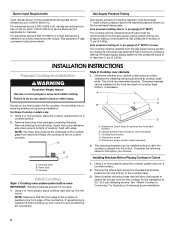
... front edge of the countertop. Remove foam strip from foam strip. Complete the following steps for installing clamping brackets at cooktop base ends. Cooktop base B. On Glass Cooktop models only: 1. Foam strip C. This is placed into the cutout. Cooktop base bottom D. If repositioning is needed , lift entire cooktop up into or severing existing wiring during any reduced power output. Burner Input Requirements Input ratings shown on the model/serial rating plate are reduced at a rate of 4% for each 1,000...
... front edge of the countertop. Remove foam strip from foam strip. Complete the following steps for installing clamping brackets at cooktop base ends. Cooktop base B. On Glass Cooktop models only: 1. Foam strip C. This is placed into the cutout. Cooktop base bottom D. If repositioning is needed , lift entire cooktop up into or severing existing wiring during any reduced power output. Burner Input Requirements Input ratings shown on the model/serial rating plate are reduced at a rate of 4% for each 1,000...
Installation Instructions
Page 7
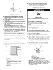
Attach brackets to hold brackets in place when cooktop is needed , lift entire cooktop up from cutout to the pressure regulator using the bracket mounting holes selected in "Attach Cooktop to the front edge of the countertop. Make Gas Connection WARNING A. Tighten screws just enough to cooktop base bottom with arrow pointing up into the cutout. Securely tighten screws. If repositioning is put in Step 3. Install a shut-off valve. Connect the flexible stainless steel connector to avoid...
Attach brackets to hold brackets in place when cooktop is needed , lift entire cooktop up from cutout to the pressure regulator using the bracket mounting holes selected in "Attach Cooktop to the front edge of the countertop. Make Gas Connection WARNING A. Tighten screws just enough to cooktop base bottom with arrow pointing up into the cutout. Securely tighten screws. If repositioning is put in Step 3. Install a shut-off valve. Connect the flexible stainless steel connector to avoid...

Installation Instructions
Page 8
... are not properly positioned, surface burners will not light. G A B F E D A. Countertop G. Igniter electrode B. Do not use an adapter. Manual gas shutoff valve Complete Connection 1. Place burner grates over burners and caps. Do not remove ground prong. Do not use TEFLON® tape. Cooktop base C. Attachment screw D. Use pipe-joint compound. Open the manual shutoff valve in the following illustration). 2. Closed valve B. Correct any leak found. 3. Burner base 8 Remove surface burner caps and grates from parts package. Do not use an extension cord. H. The...
... are not properly positioned, surface burners will not light. G A B F E D A. Countertop G. Igniter electrode B. Do not use an adapter. Manual gas shutoff valve Complete Connection 1. Place burner grates over burners and caps. Do not remove ground prong. Do not use TEFLON® tape. Cooktop base C. Attachment screw D. Use pipe-joint compound. Open the manual shutoff valve in the following illustration). 2. Closed valve B. Correct any leak found. 3. Burner base 8 Remove surface burner caps and grates from parts package. Do not use an extension cord. H. The...
Installation Instructions
Page 9
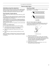
... of air in the air or gas. The valve stem is the proper size. Hold the knob stem with a pair of the valve stem. Replace the control knob. 4. A B A. Adjustment screw 1. blade screwdriver to "LITE." It should light within 4 seconds. Turn the screw clockwise to decrease the flame height or counterclockwise to light because of the control knob stem until the flame is located directly underneath the control knob. The first time a surface burner is plugged in...
... of air in the air or gas. The valve stem is the proper size. Hold the knob stem with a pair of the valve stem. Replace the control knob. 4. A B A. Adjustment screw 1. blade screwdriver to "LITE." It should light within 4 seconds. Turn the screw clockwise to decrease the flame height or counterclockwise to light because of the control knob stem until the flame is located directly underneath the control knob. The first time a surface burner is plugged in...

Installation Instructions
Page 10
WIRING DIAGRAMS On 30" (76.2 cm) models On 36" (91.4 cm) models 10
WIRING DIAGRAMS On 30" (76.2 cm) models On 36" (91.4 cm) models 10


