

Owner's Manual
Page 2
...power cord from being walked on or pinched particularly at plugs, convenience receptacles, and the point where they exit from tip-over. 13 Unplug this apparatus near any ventilation openings. Install in any way, such as practical. 1 Read these instructions. 2 Keep these instructions. 3 Heed all warnings. 4 Follow all servicing to qualified service... . NO USER-SERVICEABLE PARTS INSIDE. If the provided plug does not fit into the apparatus, the apparatus has been exposed to Article 820-40 of the NEC that provides guidelines for replacement of the polarized or grounding-type plug.
...power cord from being walked on or pinched particularly at plugs, convenience receptacles, and the point where they exit from tip-over. 13 Unplug this apparatus near any ventilation openings. Install in any way, such as practical. 1 Read these instructions. 2 Keep these instructions. 3 Heed all warnings. 4 Follow all servicing to qualified service... . NO USER-SERVICEABLE PARTS INSIDE. If the provided plug does not fit into the apparatus, the apparatus has been exposed to Article 820-40 of the NEC that provides guidelines for replacement of the polarized or grounding-type plug.
Owner's Manual
Page 3
... contact Yamaha Electronics Corp., U.S.A. 6660 Orangethorpe Ave., Buena Park, CA 90620. IMPORTANT SAFETY INSTRUCTIONS FCC INFORMATION (for Class "B" digital devices. This product, when installed as indicated in the instructions contained in the users manual, may void your FCC authorization to coaxial type cable. If this product is found to comply with this manual, meets FCC requirements. If you can be used according...
... contact Yamaha Electronics Corp., U.S.A. 6660 Orangethorpe Ave., Buena Park, CA 90620. IMPORTANT SAFETY INSTRUCTIONS FCC INFORMATION (for Class "B" digital devices. This product, when installed as indicated in the instructions contained in the users manual, may void your FCC authorization to coaxial type cable. If this product is found to comply with this manual, meets FCC requirements. If you can be used according...
Owner's Manual
Page 4
... not plug in standby mode, and disconnect the power supply cable from the wall outlet, grasp the plug; Use a clean, dry cloth. 12 Only voltage specified on the back of this unit. 3 Locate this unit away from other than specified is connected to a wall outlet until all connections are complete. 8 Do not operate this unit for any service is needed. vacation), disconnect the AC power plug from use...
... not plug in standby mode, and disconnect the power supply cable from the wall outlet, grasp the plug; Use a clean, dry cloth. 12 Only voltage specified on the back of this unit. 3 Locate this unit away from other than specified is connected to a wall outlet until all connections are complete. 8 Do not operate this unit for any service is needed. vacation), disconnect the AC power plug from use...
Owner's Manual
Page 5
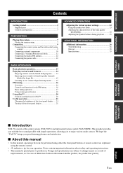
... contain important information about safety and operating instructions. • This manual is printed prior to change in part as a result of improvements, etc. Design and specifications are explained using the remote control. • y indicates a tip for iPod 20 Useful operation 21 Changing the brightness of the front panel display ..... 21 Turning off the front panel display 21 ADVANCED OPERATION Adjusting the virtual speaker settings 22 Using the speaker test mode 23 Adjusting the characteristics of...
... contain important information about safety and operating instructions. • This manual is printed prior to change in part as a result of improvements, etc. Design and specifications are explained using the remote control. • y indicates a tip for iPod 20 Useful operation 21 Changing the brightness of the front panel display ..... 21 Turning off the front panel display 21 ADVANCED OPERATION Adjusting the virtual speaker settings 22 Using the speaker test mode 23 Adjusting the characteristics of...
Owner's Manual
Page 6
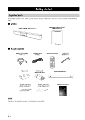
... control (YAS-70SPX) x 1 ■ Accessories System control cable (4 m) x 1 Spacer x 2 Speaker cable (4 m) x 2 Remote control x 1 STANDBY/ON MOVIE MUSIC SPORTS GAME INPUT 1 INPUT 2 INPUT 3 DOCK FM INPUT VOLUME MENU MUTE A-E A-E ENTER PRESET AUTO /TUNE /MAN'L MEMORY SW NIGHT DEC MODE CENTER DISP. MODE DIMMER ROOM EQ TEST L R SUR Indoor FM antenna x 1 Battery x 2 (AAA, R03, UM4) Mounting template x 1 Double-sided tape (Small, 4 pieces) x 1 Double-sided tape (Large, 2 pieces) x 2 Note The form of the following parts. Before making connections, make...
... control (YAS-70SPX) x 1 ■ Accessories System control cable (4 m) x 1 Spacer x 2 Speaker cable (4 m) x 2 Remote control x 1 STANDBY/ON MOVIE MUSIC SPORTS GAME INPUT 1 INPUT 2 INPUT 3 DOCK FM INPUT VOLUME MENU MUTE A-E A-E ENTER PRESET AUTO /TUNE /MAN'L MEMORY SW NIGHT DEC MODE CENTER DISP. MODE DIMMER ROOM EQ TEST L R SUR Indoor FM antenna x 1 Battery x 2 (AAA, R03, UM4) Mounting template x 1 Double-sided tape (Small, 4 pieces) x 1 Double-sided tape (Large, 2 pieces) x 2 Note The form of the following parts. Before making connections, make...

Owner's Manual
Page 7
... from the remote control. (☞ P. 5) -STAVIN ONLDPUBUM YT/EON+ INPUT - INTRODUCTION Controls and functions ■ Front panel of the center system Getting started Front panel display Shows the information about the operational status of this system. (☞ P. 13) INPUT Selects an input source you want to listen to the standby mode. (☞ P. 13) 3 En English VOLUME + STANDBY/ON Power indicator Lights up when this system is turned on...
... from the remote control. (☞ P. 5) -STAVIN ONLDPUBUM YT/EON+ INPUT - INTRODUCTION Controls and functions ■ Front panel of the center system Getting started Front panel display Shows the information about the operational status of this system. (☞ P. 13) INPUT Selects an input source you want to listen to the standby mode. (☞ P. 13) 3 En English VOLUME + STANDBY/ON Power indicator Lights up when this system is turned on...
Owner's Manual
Page 8
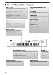
... sound field program and other information is displayed. Getting started ■ Front panel display of the center system DSP indicators CINEMA DSP indicator Lights up when CINEMA DSP is activated. (☞ P. 14) HiFi DSP indicator Lights up when HiFi DSP is activated. (☞ P. 14) DOCK indicator Lights up when this unit recognizes iPod. (☞ P. 12) NIGHT indicator Lights up when you are adjusting or changing setting...
... sound field program and other information is displayed. Getting started ■ Front panel display of the center system DSP indicators CINEMA DSP indicator Lights up when CINEMA DSP is activated. (☞ P. 14) HiFi DSP indicator Lights up when HiFi DSP is activated. (☞ P. 14) DOCK indicator Lights up when this unit recognizes iPod. (☞ P. 12) NIGHT indicator Lights up when you are adjusting or changing setting...
Owner's Manual
Page 9
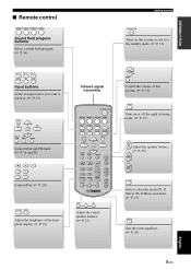
... Adjust the brightness of this system. (☞ P. 13) NIGHT Turns on this system or sets it to the standby mode. (☞ P. 13) INPUT 1 INPUT 2 INPUT 3 DOCK FM INPUT Input buttons Select an input source you want to listen to. (☞ P. 13) MENU A E ENTER A E PRESET AUTO /TUNE /MAN'L MEMORY Control iPod and FM tuner. (☞ P. 16 and 20) Control iPod. (☞ P. 20) DISP. INTRODUCTION ■ Remote control MOVIE MUSIC SPORTS GAME Sound...
... Adjust the brightness of this system. (☞ P. 13) NIGHT Turns on this system or sets it to the standby mode. (☞ P. 13) INPUT 1 INPUT 2 INPUT 3 DOCK FM INPUT Input buttons Select an input source you want to listen to. (☞ P. 13) MENU A E ENTER A E PRESET AUTO /TUNE /MAN'L MEMORY Control iPod and FM tuner. (☞ P. 16 and 20) Control iPod. (☞ P. 20) DISP. INTRODUCTION ■ Remote control MOVIE MUSIC SPORTS GAME Sound...
Owner's Manual
Page 11
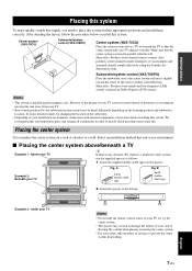
... aligned vertically. Main roles: Produces front channel (stereo) sounds. Notes • This system is shielded against magnetic rays. However, if the picture on the listening position and subwoofer location. Also produces center channel sounds (dialogues or vocal sounds) and surround channel sounds effectively using the Yamaha Air Surround system. Main roles: Produces bass sounds and low frequency (LFE) sounds contained in Dolby Digital or DTS sources. PREPARATION Placing this...
... aligned vertically. Main roles: Produces front channel (stereo) sounds. Notes • This system is shielded against magnetic rays. However, if the picture on the listening position and subwoofer location. Also produces center channel sounds (dialogues or vocal sounds) and surround channel sounds effectively using the Yamaha Air Surround system. Main roles: Produces bass sounds and low frequency (LFE) sounds contained in Dolby Digital or DTS sources. PREPARATION Placing this...

Owner's Manual
Page 12
... a wall using the holes on a wall, all installation work . When installing the center system on the back of the center system. 2 Remove the mounting template and then install the commercially available screws at the marks. 22 to 24 mm (7/7" to 15/16") 34 to 36 mm (5/16" to fall . • When connecting the center system, fix the speaker cables in personal injury. 1 Attach the supplied mounting template on a wall...
... a wall using the holes on a wall, all installation work . When installing the center system on the back of the center system. 2 Remove the mounting template and then install the commercially available screws at the marks. 22 to 24 mm (7/7" to 15/16") 34 to 36 mm (5/16" to fall . • When connecting the center system, fix the speaker cables in personal injury. 1 Attach the supplied mounting template on a wall...

Owner's Manual
Page 13
Connecting system control cable Speaker cables (supplied) SYSTEM CONNECTOR FM 75Ω UNBAL 3 L ANTENNA 1 2 DOCK R ANALOG INPUT OPTICAL COAXIAL R L SPEAKERS System control cable (supplied) SYSTEM CONNECTOR FM 75Ω UNBAL 3 L ANTENNA 1 2 DOCK R ANALOG INPUT OPTICAL COAXIAL R L SPEAKERS Tighten the screws. English 9 En Connecting speaker cables Connect the cable plug to the speaker jack of the same color. Connecting the center system and the subwoofer/system control Follow the procedure below to the speaker jack of the same color. ...
Connecting system control cable Speaker cables (supplied) SYSTEM CONNECTOR FM 75Ω UNBAL 3 L ANTENNA 1 2 DOCK R ANALOG INPUT OPTICAL COAXIAL R L SPEAKERS System control cable (supplied) SYSTEM CONNECTOR FM 75Ω UNBAL 3 L ANTENNA 1 2 DOCK R ANALOG INPUT OPTICAL COAXIAL R L SPEAKERS Tighten the screws. English 9 En Connecting speaker cables Connect the cable plug to the speaker jack of the same color. Connecting the center system and the subwoofer/system control Follow the procedure below to the speaker jack of the same color. ...

Owner's Manual
Page 14
... digital jacks support digital signals of which sampling frequency is 96 kHz or less. [INPUT 1] OPTICAL jack Example 1: DVD player TV DVD player DIGITAL OUT (OPTICAL) Optical digital cable Example 2: TV game console Game console TV OPTICAL DIGITAL OUTPUT Optical digital cable [INPUT 2] COAXIAL jack SYSTEM CONNECTOR FM 75Ω UNBAL 3 L ANTENNA 1 2 DOCK R ANALOG INPUT OPTICAL COAXIAL R L SPEAKERS SYSTEM CONNECTOR FM 75Ω UNBAL 3 L ANTENNA 1 2 DOCK R ANALOG INPUT OPTICAL COAXIAL R L SPEAKERS CD player COAXIAL DIGITAL OUTPUT Coaxial digital cable...
... digital jacks support digital signals of which sampling frequency is 96 kHz or less. [INPUT 1] OPTICAL jack Example 1: DVD player TV DVD player DIGITAL OUT (OPTICAL) Optical digital cable Example 2: TV game console Game console TV OPTICAL DIGITAL OUTPUT Optical digital cable [INPUT 2] COAXIAL jack SYSTEM CONNECTOR FM 75Ω UNBAL 3 L ANTENNA 1 2 DOCK R ANALOG INPUT OPTICAL COAXIAL R L SPEAKERS SYSTEM CONNECTOR FM 75Ω UNBAL 3 L ANTENNA 1 2 DOCK R ANALOG INPUT OPTICAL COAXIAL R L SPEAKERS CD player COAXIAL DIGITAL OUTPUT Coaxial digital cable...
Owner's Manual
Page 16
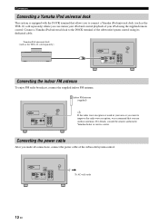
... the DOCK terminal of the subwoofer/system control. Connect a Yamaha iPod universal dock to connect a Yamaha iPod universal dock (such as the YDS-10, sold separately) where you can station your iPod and control playback of your iPod using its dedicated cable. For details, consult the nearest authorized Yamaha dealer or service center. SYSTEM CONNECTOR FM 75Ω UNBAL 3 L ANTENNA 1 2 DOCK R ANALOG INPUT OPTICAL COAXIAL R L SPEAKERS To AC wall outlet 12 En Yamaha iPod universal dock (such...
... the DOCK terminal of the subwoofer/system control. Connect a Yamaha iPod universal dock to connect a Yamaha iPod universal dock (such as the YDS-10, sold separately) where you can station your iPod and control playback of your iPod using its dedicated cable. For details, consult the nearest authorized Yamaha dealer or service center. SYSTEM CONNECTOR FM 75Ω UNBAL 3 L ANTENNA 1 2 DOCK R ANALOG INPUT OPTICAL COAXIAL R L SPEAKERS To AC wall outlet 12 En Yamaha iPod universal dock (such...

Owner's Manual
Page 17
... the DVD player. For information on and the power indicator lights up. While the mute function is turned on. 2 Press one of the subwoofer/ system control, press INPUT 1 to adjust the volume level. To resume the volume, press MUTE again. y This system has the auto-sleep function which automatically switches to the standby mode if you have finished all cable connections (see pages 9 to 12) and remote control preparation (page...
... the DVD player. For information on and the power indicator lights up. While the mute function is turned on. 2 Press one of the subwoofer/ system control, press INPUT 1 to adjust the volume level. To resume the volume, press MUTE again. y This system has the auto-sleep function which automatically switches to the standby mode if you have finished all cable connections (see pages 9 to 12) and remote control preparation (page...

Owner's Manual
Page 18
... program descriptions STANDBY/ON Sound field program buttons GAME SPORTS MUSIC MOVIE INPUT INPUT 1 INPUT 3 2 INPUT FM VOLUME MUTE DOCK A-E MENU A-E ENTER MEMORY SW UTO L MOVIE Movie CINEMA DSP processing (see page 28) enhances the cheers and emotional whirl of the stadium with the multi speaker channels. GAME Game HiFi DSP processing gives TV games extra depth and surround. y This system automatically memorizes the settings...
... program descriptions STANDBY/ON Sound field program buttons GAME SPORTS MUSIC MOVIE INPUT INPUT 1 INPUT 3 2 INPUT FM VOLUME MUTE DOCK A-E MENU A-E ENTER MEMORY SW UTO L MOVIE Movie CINEMA DSP processing (see page 28) enhances the cheers and emotional whirl of the stadium with the multi speaker channels. GAME Game HiFi DSP processing gives TV games extra depth and surround. y This system automatically memorizes the settings...

Owner's Manual
Page 24
.../forward STANDBY/ON MOVIE MUSIC SPORTS GAME INPUT 1 INPUT 2 INPUT 3 DOCK FM INPUT VOLUME MENU MUTE A E ENTER A E PRESET AUTO /TUNE /MAN'L MEMORY SW NIGHT DEC. Using iPod™ Using iPod™ You can be compatible depending on the model or the software version of your iPod. • For a complete list of the selected menu level, or change the selected setting. Notes • Operations can play back the audio sources stored on your iPod on...
.../forward STANDBY/ON MOVIE MUSIC SPORTS GAME INPUT 1 INPUT 2 INPUT 3 DOCK FM INPUT VOLUME MENU MUTE A E ENTER A E PRESET AUTO /TUNE /MAN'L MEMORY SW NIGHT DEC. Using iPod™ Using iPod™ You can be compatible depending on the model or the software version of your iPod. • For a complete list of the selected menu level, or change the selected setting. Notes • Operations can play back the audio sources stored on your iPod on...

Owner's Manual
Page 30
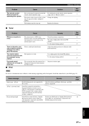
...-frequency equipment. The center speaker channel makes no sound. The subwoofer makes no sound. This system does not operate properly. The cables may be placed close to the standby mode, and then disconnect the power cable. Make sure the power cable is poor (noisy). Cancel the mute function. Make sure all cables are connected properly. Press sound field program button to the standby mode, and then disconnect the power cable. Adjust the volume level of the subwoofer. Increase the output level of the surround speaker channels...
...-frequency equipment. The center speaker channel makes no sound. The subwoofer makes no sound. This system does not operate properly. The cables may be placed close to the standby mode, and then disconnect the power cable. Make sure the power cable is poor (noisy). Cancel the mute function. Make sure all cables are connected properly. Press sound field program button to the standby mode, and then disconnect the power cable. Adjust the volume level of the subwoofer. Increase the output level of the surround speaker channels...
Owner's Manual
Page 31
...). Use the manual tuning method. Your iPod was removed from a Yamaha iPod universal dock (such as YDS-10, sold separately) connected to the DOCK terminal of this system. Replace the batteries. Use the manual tuning method. The desired station cannot be worn out. Try using a high-quality directional FM antenna. Adjust the antenna position to "Remote control". Only iPod (Click and Wheel), iPod nano, and iPod mini are supported. Additional information Problem The remote control does...
...). Use the manual tuning method. Your iPod was removed from a Yamaha iPod universal dock (such as YDS-10, sold separately) connected to the DOCK terminal of this system. Replace the batteries. Use the manual tuning method. The desired station cannot be worn out. Try using a high-quality directional FM antenna. Adjust the antenna position to "Remote control". Only iPod (Click and Wheel), iPod nano, and iPod mini are supported. Additional information Problem The remote control does...

Owner's Manual
Page 32
... frequency The number of Pro Logic II playback, including separate left , center, and right) and 2 surround stereo channels, Dolby Digital provides five full-range audio channels. With 3 front channels (left and right surround channels. ■ DTS Digital surround sound system developed by Yamaha enables the surround sound field. In comparison with Dolby Surround Pro Logic II decoders, soundtracks will be able to be encoded specifically to automotive sound. Since home conditions, such as room size, wall...
... frequency The number of Pro Logic II playback, including separate left , center, and right) and 2 surround stereo channels, Dolby Digital provides five full-range audio channels. With 3 front channels (left and right surround channels. ■ DTS Digital surround sound system developed by Yamaha enables the surround sound field. In comparison with Dolby Surround Pro Logic II decoders, soundtracks will be able to be encoded specifically to automotive sound. Since home conditions, such as room size, wall...
Owner's Manual
Page 33
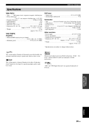
... • Antenna Input (unbalanced 75 Ω Subwoofer • Type Advanced Yamaha Active Servo Technology System • Output Power 50 W (100 Hz, 5Ω, 10% T.H.D) • Dynamic Power 100 W, 5Ω • Driver 16 cm (6 1/2") cone, Magnetic shielding type • Frequency Response 30 Hz to 200 Hz • Input impedance 12 kΩ Other sections • Power supply AC 120 V, 60 Hz • Power consumption 60 W • Standby Power Consumption 0.9 W • Dimensions (W × H ×...
... • Antenna Input (unbalanced 75 Ω Subwoofer • Type Advanced Yamaha Active Servo Technology System • Output Power 50 W (100 Hz, 5Ω, 10% T.H.D) • Dynamic Power 100 W, 5Ω • Driver 16 cm (6 1/2") cone, Magnetic shielding type • Frequency Response 30 Hz to 200 Hz • Input impedance 12 kΩ Other sections • Power supply AC 120 V, 60 Hz • Power consumption 60 W • Standby Power Consumption 0.9 W • Dimensions (W × H ×...


