
User Manual
Page 1
... Switch) Example 1 - Code Settings Note: Most single system installations will not require any specific information pertaining to a different code. This manual applies to match. Indicates Position of switches 1 through 3 set the code setting to the following products: • Wireless Transmitters (Indoor / Outdoor) - 180° Motion Sensor - 240° Motion Sensor - Transmitter(s)/ Receiver(s) Code Group "A" Group "A" © 2009 HeathCo LLC Group "B" 598-1306-07 Switch 4 sets the Group (A or B). ENGLISH Lighting Controls PAGE REFERENCE GUIDE...
... Switch) Example 1 - Code Settings Note: Most single system installations will not require any specific information pertaining to a different code. This manual applies to match. Indicates Position of switches 1 through 3 set the code setting to the following products: • Wireless Transmitters (Indoor / Outdoor) - 180° Motion Sensor - 240° Motion Sensor - Transmitter(s)/ Receiver(s) Code Group "A" Group "A" © 2009 HeathCo LLC Group "B" 598-1306-07 Switch 4 sets the Group (A or B). ENGLISH Lighting Controls PAGE REFERENCE GUIDE...

User Manual
Page 2
... Floodlight Code Switches ON Wall Switch Receiver Note: The "X" has been placed on the switches to help clarify the code settings on the previous page. ON 1 2 3 4 Close-Up of Typical Code Switch (Factory Default Setting is Off) 2 598-1306-07 Code Switch Locations Code Switches DAY NIGHT NIGHT ONLY 1234 CODES DETECT 180° Motion Sensor Code Switches CODES DETECT 1 2 3 4 DAY NIGHT NIGHT ONLY 240° Motion Sensor CR2032 3 VOLTS ON 12 34 Code Switches Entry Switch Code Switches LAMP MODE switches...
... Floodlight Code Switches ON Wall Switch Receiver Note: The "X" has been placed on the switches to help clarify the code settings on the previous page. ON 1 2 3 4 Close-Up of Typical Code Switch (Factory Default Setting is Off) 2 598-1306-07 Code Switch Locations Code Switches DAY NIGHT NIGHT ONLY 1234 CODES DETECT 180° Motion Sensor Code Switches CODES DETECT 1 2 3 4 DAY NIGHT NIGHT ONLY 240° Motion Sensor CR2032 3 VOLTS ON 12 34 Code Switches Entry Switch Code Switches LAMP MODE switches...
User Manual
Page 3
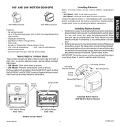
... 70 feet sensing range, 180° or 240° Coverage (Depending upon model). • Adjustable sensitivity. • Day/Night or Night only operation. • Test mode. • DualBrite® Mode (240° Motion Sensor Only). • 180° Uses 2 AA batteries. • 240° Uses 2 AAA batteries. • Wall or eave mount. • Controls receivers up to a sturdy object (i.e. Attach motion sensor mounting bracket to 100 feet (30 m) away. Install motion sensor to detect motion day...
... 70 feet sensing range, 180° or 240° Coverage (Depending upon model). • Adjustable sensitivity. • Day/Night or Night only operation. • Test mode. • DualBrite® Mode (240° Motion Sensor Only). • 180° Uses 2 AA batteries. • 240° Uses 2 AAA batteries. • Wall or eave mount. • Controls receivers up to a sturdy object (i.e. Attach motion sensor mounting bracket to 100 feet (30 m) away. Install motion sensor to detect motion day...

User Manual
Page 4
Set the ON-TIME control to the TEST position. Walk in front of LED light). 2. The LED indicator light should flash when motion is detected (see illustration for location of motion sensor. Adjust RANGE Control. Note: If the RANGE is detected (1 or 5 minutes). DualBrite® Dimmer Control (240° Motion Sensor Only) Light comes on half power for selected time after motion is set too high, false triggering may trigger the shut-off . Select...
Set the ON-TIME control to the TEST position. Walk in front of LED light). 2. The LED indicator light should flash when motion is detected (see illustration for location of motion sensor. Adjust RANGE Control. Note: If the RANGE is detected (1 or 5 minutes). DualBrite® Dimmer Control (240° Motion Sensor Only) Light comes on half power for selected time after motion is set too high, false triggering may trigger the shut-off . Select...

User Manual
Page 5
ENGLISH 8 ft. (2.4 m) 180° Motion Motion 70 ft. (21 m) Maximum Range Maximum Coverage Angle 180° Motion Sensor Coverage Area Sensor Least Sensitive Sensor Most Sensitive The detector is most sensitive to motion across its field of view. Motion Sensor Sensitivity 8 ft. (2.4 m) 240° 70 ft. (21 m) Maximum Range Maximum Coverage Angle 240° Motion Sensor Coverage Area Aim Sensor Down for Short Coverage Aim Sensor Higher for Long Coverage Adjusting Motion Sensor Coverage 598-1306-07 5
ENGLISH 8 ft. (2.4 m) 180° Motion Motion 70 ft. (21 m) Maximum Range Maximum Coverage Angle 180° Motion Sensor Coverage Area Sensor Least Sensitive Sensor Most Sensitive The detector is most sensitive to motion across its field of view. Motion Sensor Sensitivity 8 ft. (2.4 m) 240° 70 ft. (21 m) Maximum Range Maximum Coverage Angle 240° Motion Sensor Coverage Area Aim Sensor Down for Short Coverage Aim Sensor Higher for Long Coverage Adjusting Motion Sensor Coverage 598-1306-07 5

User Manual
Page 6
... 3. Stick transmitter back cover to wall using small, flat-blade screwdriver. Entry Switch Installation Note: Entry system includes a transmitter and magnet. Remove Tab from transmitter using two short screws (provided). While holding the transmitter stationary, move the magnet away from transmitter to door or window. Verify red LED on . Note: If transmitter does not operate correctly, see illustration). Mount Transmitter.
... 3. Stick transmitter back cover to wall using small, flat-blade screwdriver. Entry Switch Installation Note: Entry system includes a transmitter and magnet. Remove Tab from transmitter using two short screws (provided). While holding the transmitter stationary, move the magnet away from transmitter to door or window. Verify red LED on . Note: If transmitter does not operate correctly, see illustration). Mount Transmitter.

User Manual
Page 7
... two power wires attached to the light switch circuit before you proceed. CAUTION: Do not connect neutral (white wire) to be derated as follows: CR2032 Lithium Battery Battery Replacement Gang 300 W 500 W 1 300 W 500 W 2 300 W 475 W 3 300 W 450 W Installation 1. tion). Battery will pop up (see illustra- CAUTION: To reduce the risk of time. 1. The transmitter is shipped with 120 volt incandescent or halogen bulbs.
... two power wires attached to the light switch circuit before you proceed. CAUTION: Do not connect neutral (white wire) to be derated as follows: CR2032 Lithium Battery Battery Replacement Gang 300 W 500 W 1 300 W 500 W 2 300 W 475 W 3 300 W 450 W Installation 1. tion). Battery will pop up (see illustra- CAUTION: To reduce the risk of time. 1. The transmitter is shipped with 120 volt incandescent or halogen bulbs.

User Manual
Page 8
... and release either the top or bottom of the supplied wire connectors to 90% brightness. 6. To recall last DIM setting from 15% to secure the wires (see illustration). 7. Bulb Replacement Move the power disconnect switch to the right. Power Disconnect Switch Installing Wall Switch Receiver 8 598-1306-07 4. Connect one of the black power wires from receiver to one of DIM button and release. Route...
... and release either the top or bottom of the supplied wire connectors to 90% brightness. 6. To recall last DIM setting from 15% to secure the wires (see illustration). 7. Bulb Replacement Move the power disconnect switch to the right. Power Disconnect Switch Installing Wall Switch Receiver 8 598-1306-07 4. Connect one of the black power wires from receiver to one of DIM button and release. Route...

User Manual
Page 9
Lamp Modes There are three lamp modes (light turn -on effect (Normal, Soft, Flash). 4. Remove the existing light fixture. 2. Note: The plastic hanger can be used with receiver (see transmitter instructions). Set the LAMP MODE switch to the desired light turn -on to toggle between AUTO and MANUAL MODE. Screw incandescent bulb up to 75 Watt maximum incandescent, or 120 Watt maximum halogen, per lampholder). • Minimal wiring required. • Install fixture in the center of...
Lamp Modes There are three lamp modes (light turn -on effect (Normal, Soft, Flash). 4. Remove the existing light fixture. 2. Note: The plastic hanger can be used with receiver (see transmitter instructions). Set the LAMP MODE switch to the desired light turn -on to toggle between AUTO and MANUAL MODE. Screw incandescent bulb up to 75 Watt maximum incandescent, or 120 Watt maximum halogen, per lampholder). • Minimal wiring required. • Install fixture in the center of...

User Manual
Page 10
... out of Purchase. Short term power line failure. 2. SOLUTION 1. Check battery charge and replace if necessary. 7. Test using different device. 1. Same as 5, 6, and 7 above . 1. Another transmitter on randomly. Verify code settings on . 2. If the problem persists, call 1-800-858-8501 (English speaking only) for this guide. No Service Parts Available for assistance before returning product to 4:30 PM CST (M-F). Interrupted...
... out of Purchase. Short term power line failure. 2. SOLUTION 1. Check battery charge and replace if necessary. 7. Test using different device. 1. Same as 5, 6, and 7 above . 1. Another transmitter on randomly. Verify code settings on . 2. If the problem persists, call 1-800-858-8501 (English speaking only) for this guide. No Service Parts Available for assistance before returning product to 4:30 PM CST (M-F). Interrupted...

User Manual
Page 11
..., installation, setup time, loss of Industry Canada. ENGLISH Regulatory Information This device complies with our products. TWO YEAR LIMITED WARRANTY This is cautioned that a customer uses in its entirety. Repair service, adjustment and calibration due to you specific legal rights. REPAIR OR REPLACEMENT SHALL BE THE SOLE REMEDY OF THE CUSTOMER AND THERE SHALL BE NO LIABILITY ON THE PART OF HeathCo...
..., installation, setup time, loss of Industry Canada. ENGLISH Regulatory Information This device complies with our products. TWO YEAR LIMITED WARRANTY This is cautioned that a customer uses in its entirety. Repair service, adjustment and calibration due to you specific legal rights. REPAIR OR REPLACEMENT SHALL BE THE SOLE REMEDY OF THE CUSTOMER AND THERE SHALL BE NO LIABILITY ON THE PART OF HeathCo...


