HP Dv5 1015nr Support Question
HP Dv5 1015nr Support Question
Find answers below for this question about HP Dv5 1015nr - Pavilion - Core 2 Duo GHz.Need a HP Dv5 1015nr manual? We have 1 online manual for this item!
Question posted by ramjeedinkar on September 13th, 2014
Lock Broken Of Cm 1015 Color Printer Toner Can Not Instal
The person who posted this question about this HP product did not include a detailed explanation. Please use the "Request More Information" button to the right if more details would help you to answer this question.
Current Answers
Related HP Dv5 1015nr Manual Pages
Service Guide - Page 3

... surface temperature limits defined by the International Standard for Safety of overheating the computer, do not allow another hard surface, such as an adjoining optional printer, or a soft surface, such as pillows or rugs or clothing, during operation. iii Also, do not place the computer directly on a hard, flat surface.
To...
Service Guide - Page 54

... or microcircuitry. Grounding guidelines
Electrostatic discharge damage
Electronic components are ready to install them. Circuitry design and structure determine the degree of bench worker Removing DIPS...V.
An electronic device exposed to the computer when you are removing or installing internal components, observe these precautions:
Keep components in their electrostatic-safe containers ...
Service Guide - Page 60

... Intel processors
Spare part number 484172-001 484171-001 484170-002
484170-001
Before disassembling the computer, follow these steps: 1. The battery release latch automatically locks the battery into the battery bay and pivot the front edge of the battery into place.
52 Chapter 4 Removal and replacement procedures Disconnect the power...
Service Guide - Page 62

... module. Release the webcam/microphone module (1) from the display enclosure.
5. Disconnect the webcam/microphone module cable (2) from the webcam/microphone module.
7. Reverse this procedure to install the webcam/microphone module.
54 Chapter 4 Removal and replacement procedures 4.
Service Guide - Page 64

...
drive. 8. Remove the optical drive. 6. Reverse this procedure to slide the optical drive (3) out of the computer.
5. Use the disc tray frame to reassemble and install the optical drive.
56 Chapter 4 Removal and replacement procedures
Remove the optical drive bracket (2).
Service Guide - Page 66

... module slot. Remove the TV tuner module (3) by pulling the module away from the computer.)
6. NOTE: The TV tuner module is designed with a notch (4) to install the TV tuner module.
58 Chapter 4 Removal and replacement procedures Remove the two Phillips PM2.0×4.0 screws (2) that secure the TV tuner module to the...
Service Guide - Page 67

...system. 2. Remove the Mini Card module compartment cover (see Battery on page 57). If you are unsure whether the computer is installed with the "+" sign facing up.
RTC battery
NOTE: Removing the RTC battery and leaving it down the computer.
Description RTC ... on , and then shut it uninstalled for 5 or more minutes causes all external devices connected to install the RTC battery.
Service Guide - Page 69

Component replacement procedures 61 Reverse this procedure to prevent incorrect insertion into the memory module slot. Remove the module (2) by pulling it away from the slot at an angle. NOTE: Memory modules are designed with a notch (3) to install a memory module.
5.
Service Guide - Page 72

... drive (2) Left and right hard drive bracket rails (3) Mylar cover with tab (4) Four rubber isolators (5) Hard drive connector cable
Reverse this procedure to reassemble and install the hard drive.
64 Chapter 4 Removal and replacement procedures 7.
Service Guide - Page 76

... then contact technical support through Help and Support. 1. Reverse this procedure to the WLAN module "Main" terminal. The white WLAN antenna cable is connected to install a WLAN module.
68 Chapter 4 Removal and replacement procedures
If you replace the module and then receive a warning message, remove the module to the WLAN module...
Service Guide - Page 80

... board. 13. Disconnect the LED board cable (2) from the system board.
11. 10. Remove the keyboard. 12. Release the zero insertion force (ZIF) connector (1) to install the switch cover and keyboard.
72 Chapter 4 Removal and replacement procedures
Service Guide - Page 81

... number 486796-001
Before removing the power button board, follow these steps: 1. Disconnect all external devices connected to the switch cover. 3.
Reverse this procedure to install the power button board.
Service Guide - Page 82

.... 2.
Remove the switch cover and keyboard (see Battery on page 52). 5. Remove the speaker assembly (3). Remove the speaker assembly: 1. Disconnect all external devices connected to install the speaker assembly. 74 Chapter 4 Removal and replacement procedures Speaker assembly
Description Speaker assembly
Spare part number 486801-001
Before removing the speaker assembly, follow...
Service Guide - Page 83

... number 412766-002 483113-001
Before removing the Bluetooth module, follow these steps: 1. Remove the Phillips PM2.0×4.0 screw (1) that secures the Bluetooth module to install the Bluetooth module. Disconnect the Bluetooth module cable (3) from the computer. 4. Reverse this procedure to the top cover. 2. If you are unsure whether the computer...
Service Guide - Page 91

Reverse this procedure to reassemble and install the display assembly. The display hinges are available in the Display Hinge Kit, spare part 486534-001.
Component replacement procedures 83 The display hinge screws are available in the Display Hinge Kit Screw Kit, spare part number 485344-001. 31. Remove the display hinges (2).
Service Guide - Page 94

Remove the two Phillips PM2.5×6.0 screws (2) that secure the top cover to install the top cover.
86 Chapter 4 Removal and replacement procedures Reverse this procedure to the computer. 8. Remove the top cover (2) by lifting it rests at an angle. 9.
Lift the rear edge of the top cover (1) until it straight up. 7.
Service Guide - Page 96

Reverse this procedure to disconnect it from the system board. Lift the modem module (3) straight up to install the modem module.
88 Chapter 4 Removal and replacement procedures 3.
Service Guide - Page 98

... 69). Speaker assembly (see Battery on , and then shut it down the computer. e. Remove the Phillips PM2.5×7.0 screw (2) that secures the USB board to install the audio/infrared board. Disconnect all external devices connected to the computer. 3. If you are unsure whether the computer is off or in Hibernation, turn...
Service Guide - Page 111
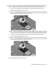
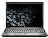
...processor removal information for computer models equipped with AMD processors. Reverse this procedure to install the processor.
Lift the processor (2) straight up and remove it . Component replacement... the processor socket when you install the processor. NOTE: Steps 1 and 2 apply only to computer models equipped with Intel processors. 1. Turn the processor locking screw (1) one -half turn...
Service Guide - Page 118

... this range of temperatures.
15.4-inch, SXGA+ display specifications
Dimensions Height Width Diagonal Number of colors Contrast ratio Brightness Pixel resolution Pitch Format Configuration Backlight Character display Total power consumption Viewing angle
Metric
U.S.
20.7 cm 33.1 cm 39.1 cm Up to 500 Hz, 0.5 oct/min sweep rate
NOTE: Applicable product safety standards specify thermal...
Similar Questions

How To Install Internal Hd On A Hp Laptop Model G60-445dx
(Posted by magicj21 9 years ago)


How To Install Built In Webcam For Elitebook Laptop 8460p
(Posted by thraiCorv 10 years ago)
How To Find Print Count For Hp Laserjet 1015 Hb Printer
how to find print count for hp LaserJet 1015 HB printer
how to find print count for hp LaserJet 1015 HB printer
(Posted by mpmm 11 years ago)

How To Install Xp For Compaq Cq57-300tu Laptop
(Posted by parveenkumar512143 11 years ago)