

Operation Manual
Page 3
... Temperature Power Supply Environment Associated equipment Warranty 3 3.1 3.1.1 3.1.2 3.1.3 3.2 3.3 3.3.1 3.3.2 3.3.3 Quick install Connections Primary connections Optional connections Powering up First-time use Quick install menu International Continuous Recording Network 4 4.1 4.2 4.3 4.3.1 4.3.2 4.4 4.5 4.6 4.7 4.8 4.9 Hardware setup Camera connections Audio connections Monitor connections VGA (Monitor A) CVBS RS-232 COM port connections Ethernet connection RS485 port USB connectors External alarm I/O connection Power supply Bosch Security Systems Installation and Operation manual...
... Temperature Power Supply Environment Associated equipment Warranty 3 3.1 3.1.1 3.1.2 3.1.3 3.2 3.3 3.3.1 3.3.2 3.3.3 Quick install Connections Primary connections Optional connections Powering up First-time use Quick install menu International Continuous Recording Network 4 4.1 4.2 4.3 4.3.1 4.3.2 4.4 4.5 4.6 4.7 4.8 4.9 Hardware setup Camera connections Audio connections Monitor connections VGA (Monitor A) CVBS RS-232 COM port connections Ethernet connection RS485 port USB connectors External alarm I/O connection Power supply Bosch Security Systems Installation and Operation manual...

Operation Manual
Page 4
... Operating instructions Front panel controls Keys Indicators Mouse Controls Remote control Viewing pictures Monitor A Monitor B Viewing Live and playback Live mode Playback mode Overview of the menu system Access using the front panel keys Access using the mouse Main menu Search Date/time search Event search Smart search Export System information Log Triggers and alarms Alarm inputs Motion events Video loss alarm Multiple alarms 6 6.1 6.1.1 6.1.2 6.1.3 6.1.4 6.1.5 6.1.6 6.1.7 6.1.8 6.2 6.2.1 6.3 6.3.1 6.3.2 6.3.3 6.4 Configuration menu Camera Camera Video adjustment PTZ Continuous Recording...
... Operating instructions Front panel controls Keys Indicators Mouse Controls Remote control Viewing pictures Monitor A Monitor B Viewing Live and playback Live mode Playback mode Overview of the menu system Access using the front panel keys Access using the mouse Main menu Search Date/time search Event search Smart search Export System information Log Triggers and alarms Alarm inputs Motion events Video loss alarm Multiple alarms 6 6.1 6.1.1 6.1.2 6.1.3 6.1.4 6.1.5 6.1.6 6.1.7 6.1.8 6.2 6.2.1 6.3 6.3.1 6.3.2 6.3.3 6.4 Configuration menu Camera Camera Video adjustment PTZ Continuous Recording...

Operation Manual
Page 5
...8.4.1 8.5 8.5.1 8.6 8.7 8.8 8.9 Input Motion Network TCP/IP DDNS Notification Mail System Date/Time NTP Beeper Users Configuration Hard Disk System Web Client Software Getting started System requirements Connecting to the DVR 400 Series the first time How to log on Menu structure differences Introducing the browser window Live mode Camera views Playback mode Export mode Configuration mode Archive Player Getting started System requirements Installation Starting the Program Introducing the main window Open button Camera Views Viewing Images Assigning Cameos Using the playback controls Capturing...
...8.4.1 8.5 8.5.1 8.6 8.7 8.8 8.9 Input Motion Network TCP/IP DDNS Notification Mail System Date/Time NTP Beeper Users Configuration Hard Disk System Web Client Software Getting started System requirements Connecting to the DVR 400 Series the first time How to log on Menu structure differences Introducing the browser window Live mode Camera views Playback mode Export mode Configuration mode Archive Player Getting started System requirements Installation Starting the Program Introducing the main window Open button Camera Views Viewing Images Assigning Cameos Using the playback controls Capturing...

Operation Manual
Page 8
... the service technician uses replacement parts specified by the manufacturer. Unauthorized substitutions could void the warranty or, in hazardous radiation exposure. 8. Video Recorder 400 Series Safety | en 8 adjustments, or performance of procedures other than those specified, may expose you to ensure proper operating condition. 16. Overloading - Power sources - Unplug the unit from the cable to qualified service personnel. 13. the power supply cord or plug...
... the service technician uses replacement parts specified by the manufacturer. Unauthorized substitutions could void the warranty or, in hazardous radiation exposure. 8. Video Recorder 400 Series Safety | en 8 adjustments, or performance of procedures other than those specified, may expose you to ensure proper operating condition. 16. Overloading - Power sources - Unplug the unit from the cable to qualified service personnel. 13. the power supply cord or plug...
Operation Manual
Page 13
... alarm outputs, audio inputs, and a DVD burner. Looping auto-terminating video inputs and outputs, audio inputs and outputs, and alarm inputs and outputs are various DVR 400 Series models: 4-channel basic and 4-channel advanced. a detailed description for viewing stored video. The unit has comprehensive search and playback facilities for installers on -screen display menu system. Web Control and Archive Player - Use the Control Center Web application via the front panel control keys, mouse, and the on how to set up and install the product...
... alarm outputs, audio inputs, and a DVD burner. Looping auto-terminating video inputs and outputs, audio inputs and outputs, and alarm inputs and outputs are various DVR 400 Series models: 4-channel basic and 4-channel advanced. a detailed description for viewing stored video. The unit has comprehensive search and playback facilities for installers on -screen display menu system. Web Control and Archive Player - Use the Control Center Web application via the front panel control keys, mouse, and the on how to set up and install the product...

Operation Manual
Page 14
...: - VGA monitor output (Monitor A) - Audio output (mono) - Audible alarm - Unpack carefully. If any items are damaged. Package contents Check for visible damage. Power supply cords - Terminal blocks for Ethernet connection and networking - Do not attempt to the unit. Digital Video Recorder (DVR 400 Series unit) - Simultaneous recording and playback - CVBS monitor output (Monitor B) - Full-screen in live with 2 AAA Batteries - USB Mouse - If any components are missing, notify your customer service representative or Bosch Security...
...: - VGA monitor output (Monitor A) - Audio output (mono) - Audible alarm - Unpack carefully. If any items are damaged. Package contents Check for visible damage. Power supply cords - Terminal blocks for Ethernet connection and networking - Do not attempt to the unit. Digital Video Recorder (DVR 400 Series unit) - Simultaneous recording and playback - CVBS monitor output (Monitor B) - Full-screen in live with 2 AAA Batteries - USB Mouse - If any components are missing, notify your customer service representative or Bosch Security...
Operation Manual
Page 15
... video outputs - Temperature Observe the unit's ambient temperature specifications when choosing an installation space. Power Supply Ensure that they are not obstructed. Primary VGA monitor for the installation of dust may cause the unit to fail. Ventilation Ensure that allows for secure isolation (for spot/alarm monitoring (monitor B) - PC and network for connecting the video signals - Video Recorder 400 Series Introduction | en 15 2.3 2.3.1 2.3.2 2.3.3 2.3.4 2.3.5 2.4 2.5 Installation environment Mounting The DVR...
... video outputs - Temperature Observe the unit's ambient temperature specifications when choosing an installation space. Power Supply Ensure that they are not obstructed. Primary VGA monitor for the installation of dust may cause the unit to fail. Ventilation Ensure that allows for secure isolation (for spot/alarm monitoring (monitor B) - PC and network for connecting the video signals - Video Recorder 400 Series Introduction | en 15 2.3 2.3.1 2.3.2 2.3.3 2.3.4 2.3.5 2.4 2.5 Installation environment Mounting The DVR...

Operation Manual
Page 16
... 4 audio signals to a USB port. Bosch Security Systems Installation and Operation manual F.01U.168.054 | v1.1 | 2010.06 Video Recorder 400 Series Quick install | en 16 3 3.1 Quick install To get the unit quickly operational, make the connections described below and then enter the relevant data in the Quick install menu. Connect up to the RS-232 port if required. Connect the power cord to the MON B BNC connector. 2. Connect monitor B to the unit. Connect up to the VGA MON A output (supporting 800x600...
... 4 audio signals to a USB port. Bosch Security Systems Installation and Operation manual F.01U.168.054 | v1.1 | 2010.06 Video Recorder 400 Series Quick install | en 16 3 3.1 Quick install To get the unit quickly operational, make the connections described below and then enter the relevant data in the Quick install menu. Connect up to the RS-232 port if required. Connect the power cord to the MON B BNC connector. 2. Connect monitor B to the unit. Connect up to the VGA MON A output (supporting 800x600...

Operation Manual
Page 17
... Operation manual F.01U.168.054 | v1.1 | 2010.06 The main menu appears on monitor A. 3. Navigating Use the supplied USB mouse. Fill in the basic settings in screen over a quad display. Video Recorder 400 Series Quick install | en 17 3.2 First-time use the following front panel keys: - Alternatively, use The Quick install menu opens the first time the unit is closed. The unit begins recording automatically when the Quick install menu is used. Select System, then the Configuration submenu, and finally Quick install. The default User...
... Operation manual F.01U.168.054 | v1.1 | 2010.06 The main menu appears on monitor A. 3. Navigating Use the supplied USB mouse. Fill in the basic settings in screen over a quad display. Video Recorder 400 Series Quick install | en 17 3.2 First-time use the following front panel keys: - Alternatively, use The Quick install menu opens the first time the unit is closed. The unit begins recording automatically when the Quick install menu is used. Select System, then the Configuration submenu, and finally Quick install. The default User...
Operation Manual
Page 21
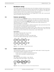
... need to add a terminator to 4 audio inputs and 1 audio output. Camera connections Connect cameras to PAL or NTSC in the 'Camera menu' under 'Video format'. If the camera signal is terminated with 75 ohm termination. Optionally, this signal can also be connected to other equipment via the corresponding VIDEO OUT connector. Specifications Input signal: Composite video 1 Vpp, 75 ohm Color standard: PAL/NTSC, auto-detect Gain control: Automatic gain control for the Advanced Recorder Bosch Security Systems Installation and Operation manual...
... need to add a terminator to 4 audio inputs and 1 audio output. Camera connections Connect cameras to PAL or NTSC in the 'Camera menu' under 'Video format'. If the camera signal is terminated with 75 ohm termination. Optionally, this signal can also be connected to other equipment via the corresponding VIDEO OUT connector. Specifications Input signal: Composite video 1 Vpp, 75 ohm Color standard: PAL/NTSC, auto-detect Gain control: Automatic gain control for the Advanced Recorder Bosch Security Systems Installation and Operation manual...

Operation Manual
Page 24
... Ethernet receive line plus No connection No connection Ethernet receive line minus No connection No connection RS485 port Connect Bosch or third-party controllable cameras to a network hub, use a cross-over network cable. no parity - To connect directly to the unit for pan, tilt, and zoom control. Consult with the following baud settings: - 9600 baud - 8 data bits - 1 stop bit - Specifications Connection: 10/100 BaseT, IEEE 802.3 Differential signal voltage: ± 2.8 V maximum, inputs have...
... Ethernet receive line plus No connection No connection Ethernet receive line minus No connection No connection RS485 port Connect Bosch or third-party controllable cameras to a network hub, use a cross-over network cable. no parity - To connect directly to the unit for pan, tilt, and zoom control. Consult with the following baud settings: - 9600 baud - 8 data bits - 1 stop bit - Specifications Connection: 10/100 BaseT, IEEE 802.3 Differential signal voltage: ± 2.8 V maximum, inputs have...

Operation Manual
Page 25
... to connect a mouse or USB memory device. 4.8 Figure 4.9 USB mouse port External alarm I/O connection Alarm inputs and outputs are supplied with the mouse. Electrical voltage. Risk of the driving event. For convenience, the USB 2.0 port is located at AC line voltages. Configure the alarm inputs as either Normally Open (N/O) or Normally Closed (N/C). Specifications Switching current (resistive): 500 mA maximum Switching voltage (resistive): 30 VAC/30 VDC maximum Cable cross...
... to connect a mouse or USB memory device. 4.8 Figure 4.9 USB mouse port External alarm I/O connection Alarm inputs and outputs are supplied with the mouse. Electrical voltage. Risk of the driving event. For convenience, the USB 2.0 port is located at AC line voltages. Configure the alarm inputs as either Normally Open (N/O) or Normally Closed (N/C). Specifications Switching current (resistive): 500 mA maximum Switching voltage (resistive): 30 VAC/30 VDC maximum Cable cross...

Operation Manual
Page 29
... playback of the System Control Bar work the same as the keys and indicators on the front panel display light or flash to step forward one minute earlier - in live mode Indicators The indicators on the front panel. - in pause mode, press to alert of the screen or press the menu key. lights green when a remote user is recording video Mouse Controls All functions controlled by the front panel can also be accessed using the supplied USB...
... playback of the System Control Bar work the same as the keys and indicators on the front panel display light or flash to step forward one minute earlier - in live mode Indicators The indicators on the front panel. - in pause mode, press to alert of the screen or press the menu key. lights green when a remote user is recording video Mouse Controls All functions controlled by the front panel can also be accessed using the supplied USB...

Operation Manual
Page 35
... Output - Language - per camera Port, Address, Protocol, and Baud Rate - Network The Network information menu contains four submenus: - Mail - set unit to beep on Input, Motion detect, Disk fail, Disk full, Fan fail, System/Disk temperature, Administrator Password change , Video loss, and Power On. per input Input Type, Camera, Relay Output, and PTZ preset - Network Live Streaming - NTSC, PAL, or Auto Detect; DDNS - Notification - System The System information menu contains seven submenus: - NTP - Continuous Recording...
... Output - Language - per camera Port, Address, Protocol, and Baud Rate - Network The Network information menu contains four submenus: - Mail - set unit to beep on Input, Motion detect, Disk fail, Disk full, Fan fail, System/Disk temperature, Administrator Password change , Video loss, and Power On. per input Input Type, Camera, Relay Output, and PTZ preset - Network Live Streaming - NTSC, PAL, or Auto Detect; DDNS - Notification - System The System information menu contains seven submenus: - NTP - Continuous Recording...

Operation Manual
Page 36
... Export configuration, reset to access the System Control Bar. 2. set Overwrite, Disk full warning, Event partition, Auto delete, and format the disk - Search Bosch Security Systems Installation and Operation manual F.01U.168.054 | v1.1 | 2010.06 System - To Search using the mouse: 1. Figure 5.6 Main menu - The default search is a Date/time search. Move the cursor to the bottom of the screen to Factory defaults, Update firmware and Quick install - Configuration - Video Recorder 400 Series Operating instructions | en 36 5.7 - Hard Disk -
... Export configuration, reset to access the System Control Bar. 2. set Overwrite, Disk full warning, Event partition, Auto delete, and format the disk - Search Bosch Security Systems Installation and Operation manual F.01U.168.054 | v1.1 | 2010.06 System - To Search using the mouse: 1. Figure 5.6 Main menu - The default search is a Date/time search. Move the cursor to the bottom of the screen to Factory defaults, Update firmware and Quick install - Configuration - Video Recorder 400 Series Operating instructions | en 36 5.7 - Hard Disk -

Operation Manual
Page 53
.... Video format Select the Video format, NTSC, PAL, or Auto detect, that the unit will be used VGA monitor (monitor A). Bosch Security Systems Installation and Operation manual F.01U.168.054 | v1.1 | 2010.06 Network Streaming performance is limited by Resolutions for enabled Channels Video format Figure 6.9 Camera - Select the VGA Output to either PAL or NTSC. When set the DVR to match the best VGA resolution on the remaining enabled channels. Video Recorder 400 Series Configuration menu...
.... Video format Select the Video format, NTSC, PAL, or Auto detect, that the unit will be used VGA monitor (monitor A). Bosch Security Systems Installation and Operation manual F.01U.168.054 | v1.1 | 2010.06 Network Streaming performance is limited by Resolutions for enabled Channels Video format Figure 6.9 Camera - Select the VGA Output to either PAL or NTSC. When set the DVR to match the best VGA resolution on the remaining enabled channels. Video Recorder 400 Series Configuration menu...

Operation Manual
Page 63
... saves a copy of the unit software. See Section 2.1.3 Firmware upgrades. - Import configuration will load previously saved system settings from the factory. Select Factory defaults to reset the settings in the menu system to a USB memory device. - Video Recorder 400 Series 6.6.5 Configuration Configuration menu | en 63 Figure 6.20 System - Configuration - Quick install opens the Quick install menu that was first presented when the unit was powered on when received from a USB memory device. - Update firmware checks a USB memory device when connected for...
... saves a copy of the unit software. See Section 2.1.3 Firmware upgrades. - Import configuration will load previously saved system settings from the factory. Select Factory defaults to reset the settings in the menu system to a USB memory device. - Video Recorder 400 Series 6.6.5 Configuration Configuration menu | en 63 Figure 6.20 System - Configuration - Quick install opens the Quick install menu that was first presented when the unit was powered on when received from a USB memory device. - Update firmware checks a USB memory device when connected for...

Operation Manual
Page 66
... Section 5 Operating instructions, page 27 chapter for example, the ability to connect via a TCP/IP network connection. Open Internet Explorer. 2. Remote control functions include pan, tilt, and zoom control of the user account, restricting the functions available to each remote user; The Web Client will not need to install the OCX again unless a new version is automatically installed on the unit. 3. for more details on using a PC. Graphics card: NVIDIA...
... Section 5 Operating instructions, page 27 chapter for example, the ability to connect via a TCP/IP network connection. Open Internet Explorer. 2. Remote control functions include pan, tilt, and zoom control of the user account, restricting the functions available to each remote user; The Web Client will not need to install the OCX again unless a new version is automatically installed on the unit. 3. for more details on using a PC. Graphics card: NVIDIA...

Operation Manual
Page 76
... menu default values Navigation Setting Default value Reset International Language English Y Time zone GMT+0 N Time format 12-hour N Time 0:00 N Date format YYYY-MM-DD N Continuous Cameras 1-4 Recording Resolution CIF Y Video quality Normal Y Frame rate 30 (NTSC)/25 (PAL) Y Convert Off Y Network Setup DVR Name 01 Y DHCP Enabled N IP address 0.0.0.0 N Subnet mask 0.0.0.0 N Table 9.2 Configuration menu default values Navigation Camera Camera Cameras 1 ~ 4 Video Adjustment Cameras 1 ~ 4 PTZ Cameras 1 ~ 4 Continuous Recording Input Recording...
... menu default values Navigation Setting Default value Reset International Language English Y Time zone GMT+0 N Time format 12-hour N Time 0:00 N Date format YYYY-MM-DD N Continuous Cameras 1-4 Recording Resolution CIF Y Video quality Normal Y Frame rate 30 (NTSC)/25 (PAL) Y Convert Off Y Network Setup DVR Name 01 Y DHCP Enabled N IP address 0.0.0.0 N Subnet mask 0.0.0.0 N Table 9.2 Configuration menu default values Navigation Camera Camera Cameras 1 ~ 4 Video Adjustment Cameras 1 ~ 4 PTZ Cameras 1 ~ 4 Continuous Recording Input Recording...

Operation Manual
Page 79
... Administrator Password 000000 Overwrite Disk Full Warning Event Partition Auto Delete Format IR Remote Control DVR Name Auto User Logout All 90% 20% Off All 01 01 Off Setting Date Time Channel Start End Event Type Channel Start End Sensitivity Area Default value Current Date Current Time 1 Start of Video Current Time All 1 Start of Video Current Time 5 Off Setting Channel Start Time End Time Default value None None None Reset N N N N N N N N Y Y Y Y Y Y Y Y Y N N Y Y N Y Y Y Y Y Reset Y Y Y Y Y Y Y Y Y Y Y Reset Y Y Y Bosch Security Systems Installation and Operation manual F.01U...
... Administrator Password 000000 Overwrite Disk Full Warning Event Partition Auto Delete Format IR Remote Control DVR Name Auto User Logout All 90% 20% Off All 01 01 Off Setting Date Time Channel Start End Event Type Channel Start End Sensitivity Area Default value Current Date Current Time 1 Start of Video Current Time All 1 Start of Video Current Time 5 Off Setting Channel Start Time End Time Default value None None None Reset N N N N N N N N Y Y Y Y Y Y Y Y Y N N Y Y N Y Y Y Y Y Reset Y Y Y Y Y Y Y Y Y Y Y Reset Y Y Y Bosch Security Systems Installation and Operation manual F.01U...


