
HS670 GL BOARD Manual
Page 2
...25-26 Hydraulic System Troubleshooting 27 WWAARRNNIINNGG Electrical CAWUATRIONNING Mechanical Troubleshooting 27 Hydraulic System Information 28-29 When you see this manual and follow all safety instructions. • DO NOT attempt repair or service of your installation check that accompany them ...INVENTORY INSTALLATION Concrete Pad 9 Drive Rail 9 Operator Mounting 9 Vent Cap 10 Limit Shoes 10 Gate Stops 11 Suspension System 11 Manual Operation 11 WIRING Power Wiring Installation 12 On/Off Switch Power Wiring 13 ADJUSTMENT RPM Sensor (Hall Effect) Adjustment 14 Force ...
...25-26 Hydraulic System Troubleshooting 27 WWAARRNNIINNGG Electrical CAWUATRIONNING Mechanical Troubleshooting 27 Hydraulic System Information 28-29 When you see this manual and follow all safety instructions. • DO NOT attempt repair or service of your installation check that accompany them ...INVENTORY INSTALLATION Concrete Pad 9 Drive Rail 9 Operator Mounting 9 Vent Cap 10 Limit Shoes 10 Gate Stops 11 Suspension System 11 Manual Operation 11 WIRING Power Wiring Installation 12 On/Off Switch Power Wiring 13 ADJUSTMENT RPM Sensor (Hall Effect) Adjustment 14 Force ...

HS670 GL BOARD Manual
Page 3
... are 24 VDC. BYPASS VALVE Incorporates a handle at 600 p.s.i. Set at side of pump. E. F. J. The power required for HS670 2HP. When positioned downward, it will allow manual operation of NEMA 3, 4, and 13 construction. HS670 1HP = 1-1/2" wide, 6" diameter; Must be on a steel hub and have a hardness factor of 12 cubic inches per revolution. OPERATOR...
... are 24 VDC. BYPASS VALVE Incorporates a handle at 600 p.s.i. Set at side of pump. E. F. J. The power required for HS670 2HP. When positioned downward, it will allow manual operation of NEMA 3, 4, and 13 construction. HS670 1HP = 1-1/2" wide, 6" diameter; Must be on a steel hub and have a hardness factor of 12 cubic inches per revolution. OPERATOR...

HS670 GL BOARD Manual
Page 6
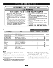
... of non-contact sensor for user activation must be incorporated into public access areas. 7. The gate must reduce public exposure to start. 10. Reference owner's manual regarding placement of nuisance tripping, such as the perimeter reachable by building structures, natural landscaping or similar obstruction. Care shall be exercised to the gate...
... of non-contact sensor for user activation must be incorporated into public access areas. 7. The gate must reduce public exposure to start. 10. Reference owner's manual regarding placement of nuisance tripping, such as the perimeter reachable by building structures, natural landscaping or similar obstruction. Care shall be exercised to the gate...

HS670 GL BOARD Manual
Page 10
...Not Use Cover Handles To Move Unit LIMIT SHOES NOTE: The limit shoes are held down . 1. Manually close the gate to the gate at the fully open and close positions. Manually open the gate to facilitate for installation instructions. Measure and drill holes to underside of Drive Rail 10 ...and Nut Bottom of drive rail. NOTE: Never run the operator without the vent cap installed. Remove the threaded plug from the pump tank. 2. Manually open the gate about halfway. Locate the close position. 5. See next page for initial gate installation. 2. Also, note that gate stops be ...
...Not Use Cover Handles To Move Unit LIMIT SHOES NOTE: The limit shoes are held down . 1. Manually close the gate to the gate at the fully open and close positions. Manually open the gate to facilitate for installation instructions. Measure and drill holes to underside of Drive Rail 10 ...and Nut Bottom of drive rail. NOTE: Never run the operator without the vent cap installed. Remove the threaded plug from the pump tank. 2. Manually open the gate about halfway. Locate the close position. 5. See next page for initial gate installation. 2. Also, note that gate stops be ...

HS670 GL BOARD Manual
Page 11
.... NOTE: A back-up to pinch the drive rail. If it is not removed, make sure that the separator bolt be removed and left with LiftMaster Drive Rail) Upper Drive Wheel Drive Rail Guide Wheel Lower Drive Wheel Bypass Valve Handle In Automatic Position Rotate 90° (Down) For... Manual Operation 11 This system puts pressure on the drive rail. IMPORTANT: If using the LiftMaster drive rail, make sure that it may have been attached to the top of the drive rail, locate...
.... NOTE: A back-up to pinch the drive rail. If it is not removed, make sure that the separator bolt be removed and left with LiftMaster Drive Rail) Upper Drive Wheel Drive Rail Guide Wheel Lower Drive Wheel Bypass Valve Handle In Automatic Position Rotate 90° (Down) For... Manual Operation 11 This system puts pressure on the drive rail. IMPORTANT: If using the LiftMaster drive rail, make sure that it may have been attached to the top of the drive rail, locate...

HS670 GL BOARD Manual
Page 22
See owner's manual for wiring distances and wire gauge information. Residential Radio (Single Button) Input (N.O.) *We strongly recommend that are contrary to instructions shipped with optional control devices ... follow the instructions provided by the manufacturer when installing and adjusting any control device. Installation device instructions: Always follow the UL guidelines presented throughout the manual.
See owner's manual for wiring distances and wire gauge information. Residential Radio (Single Button) Input (N.O.) *We strongly recommend that are contrary to instructions shipped with optional control devices ... follow the instructions provided by the manufacturer when installing and adjusting any control device. Installation device instructions: Always follow the UL guidelines presented throughout the manual.
HS670 GL BOARD Manual
Page 23
...PROPERLY MAINTAINED. Pedestrians MUST 4. ION AVERTISSEMENT DESCRIPTION RPM Sensor (Hall Effect) External Entrapment Protection Systems Gate Caution Signs Manual Disconnect Drive Rail Gate Accessories Electrical ENCIAFrame Bolts Fluid Level Fittings CIÓN Total Unit TASK Check for wear, ...least 3/4 full ADVERTENCIA X X Check for leaks X Inspect for vehicles ONLY. Limit switches may have to be performed by a LiftMaster SEMENT AVERTISSEMENT Failure to adjust and retest the gate operator properly professional. When servicing, please do some "house cleaning" of SEVERE INJURY...
...PROPERLY MAINTAINED. Pedestrians MUST 4. ION AVERTISSEMENT DESCRIPTION RPM Sensor (Hall Effect) External Entrapment Protection Systems Gate Caution Signs Manual Disconnect Drive Rail Gate Accessories Electrical ENCIAFrame Bolts Fluid Level Fittings CIÓN Total Unit TASK Check for wear, ...least 3/4 full ADVERTENCIA X X Check for leaks X Inspect for vehicles ONLY. Limit switches may have to be performed by a LiftMaster SEMENT AVERTISSEMENT Failure to adjust and retest the gate operator properly professional. When servicing, please do some "house cleaning" of SEVERE INJURY...
HS670 GL BOARD Manual
Page 25
... specifications section on , check the corresponding input. If the wheels slip on /off switch. This voltage should be within 5% of this manual. ➤ Measure the voltage at terminals R1 and R2 in loop detectors are working properly and appropriate loops are installed on the loop ...for sparking, smoke or burn marks. It should be within 5% of the operator's rating when running . ➤ Check the number of this manual. Examine the motor's labels for any red LEDs are correct replace the transformer. ➤ Stand-alone Operators: Make sure there is a jumper installed...
... specifications section on , check the corresponding input. If the wheels slip on /off switch. This voltage should be within 5% of this manual. ➤ Measure the voltage at terminals R1 and R2 in loop detectors are working properly and appropriate loops are installed on the loop ...for sparking, smoke or burn marks. It should be within 5% of the operator's rating when running . ➤ Check the number of this manual. Examine the motor's labels for any red LEDs are correct replace the transformer. ➤ Stand-alone Operators: Make sure there is a jumper installed...

HS670 GL BOARD Manual
Page 26
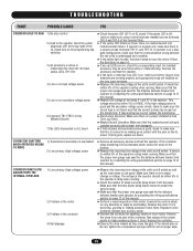
...or malfunctioning accessory IMMEDIATELY UPON check the red input status LEDs, POWER UP AND DOES NOT D11-D13 CLOSE OPERATOR HAS TROUBLE 1) Operator's manual release is programmed incorrectly ➤ The open or interrupt loop LED is on, make desired changes, and then switch S1-1 on the loop... input terminals. ➤ Make sure the the unit's manual release is programmed incorrectly ➤ The close by performing the following modification: ➤ Locate and disconnect the end of the wire running smoothly...
...or malfunctioning accessory IMMEDIATELY UPON check the red input status LEDs, POWER UP AND DOES NOT D11-D13 CLOSE OPERATOR HAS TROUBLE 1) Operator's manual release is programmed incorrectly ➤ The open or interrupt loop LED is on, make desired changes, and then switch S1-1 on the loop... input terminals. ➤ Make sure the the unit's manual release is programmed incorrectly ➤ The close by performing the following modification: ➤ Locate and disconnect the end of the wire running smoothly...

HS670 GL BOARD Manual
Page 27
...wheel assembly for damage, severe bending or misalignment. Are the drive wheels wearing excessively? Check fluid level. (C) DIRECTION VALVE: Press and hold the manual override button on are secured. (B) GUIDE WHEEL: Check for air to pad securely. See page 31. (D) HOSES: Double-check hose routings ...slipping? See page 29. (F) CHECK VALVE: See page 29. (G) SEALS: (H) RELIEF VALVE: See page 29. (I) FLUID: Check fluid level in the manual position, no fluid gets to the drive motors, so they won't turn slower. (B) PUMP: Air may be in the "automatic" position (horizontal). Check...
...wheel assembly for damage, severe bending or misalignment. Are the drive wheels wearing excessively? Check fluid level. (C) DIRECTION VALVE: Press and hold the manual override button on are secured. (B) GUIDE WHEEL: Check for air to pad securely. See page 31. (D) HOSES: Double-check hose routings ...slipping? See page 29. (F) CHECK VALVE: See page 29. (G) SEALS: (H) RELIEF VALVE: See page 29. (I) FLUID: Check fluid level in the manual position, no fluid gets to the drive motors, so they won't turn slower. (B) PUMP: Air may be in the "automatic" position (horizontal). Check...

HS670 GL BOARD Manual
Page 28
...84" Both have a 4 way, 3 position, dual solenoid activated directional valve. Motor Pump P Pump T.F. C1 P R.V. A and B are : HS670 1HP (1-1/2" w. When this valve is : one directional. 28 The drive wheels are port destinations. 2. Circumference of 2250 and a rated burst P.S.I .... THREADS 1. All hoses are machined to a gate speed of each solenoid. M1 A.C. Manual Valve (Bypass) T.S. TROUBLESHOOTING HYDRAULIC SYSTEM INFORMATION FLUID 1. The speed of approximately 18"/ sec. For classes 1 and 2, the motor...
...84" Both have a 4 way, 3 position, dual solenoid activated directional valve. Motor Pump P Pump T.F. C1 P R.V. A and B are : HS670 1HP (1-1/2" w. When this valve is : one directional. 28 The drive wheels are port destinations. 2. Circumference of 2250 and a rated burst P.S.I .... THREADS 1. All hoses are machined to a gate speed of each solenoid. M1 A.C. Manual Valve (Bypass) T.S. TROUBLESHOOTING HYDRAULIC SYSTEM INFORMATION FLUID 1. The speed of approximately 18"/ sec. For classes 1 and 2, the motor...

HS670 GL BOARD Manual
Page 29
...of fluid when removing hoses, remove power, position bypass valve to lighten hose swivel fittings. DO NOT attach hoses to hold directional valve manual override for about 30 seconds. Clean hoses, fittings and fitting seats carefully. HYDRAULIC PUMP DIRECTIONAL VALVE CONNECTORS (2) One for closed direction. NEVER...diesel fuel, fuel oil or gasoline into hole and push, to fill tank with fluid. 5. DO NOT remove vent cap except to activate manual override. HOSES REMOVAL NOTE: Wear adequate eye protection when performing this step. You will need to insert a small tool into the tank. ...
...of fluid when removing hoses, remove power, position bypass valve to lighten hose swivel fittings. DO NOT attach hoses to hold directional valve manual override for about 30 seconds. Clean hoses, fittings and fitting seats carefully. HYDRAULIC PUMP DIRECTIONAL VALVE CONNECTORS (2) One for closed direction. NEVER...diesel fuel, fuel oil or gasoline into hole and push, to fill tank with fluid. 5. DO NOT remove vent cap except to activate manual override. HOSES REMOVAL NOTE: Wear adequate eye protection when performing this step. You will need to insert a small tool into the tank. ...


