
Instruction Manual
Page 2
... AV Spring on Fuel Tank 66 AV Spring on Handlebar 67 Stop Buffers 68 Buffers on Machines with Manual Fuel Pump 85 12.5 Carburetor 88 12.5.1 Leakage Test 89 RA_737_00_01_01 MS 231, MS 231 C, MS 251, MS 251 C q © ANDREAS STIHL AG & Co. Models with QuickStop Super 24 5.4.1 Adjusting the brake cable 26 5.4.2 Brake cable Removing and Installing...
... AV Spring on Fuel Tank 66 AV Spring on Handlebar 67 Stop Buffers 68 Buffers on Machines with Manual Fuel Pump 85 12.5 Carburetor 88 12.5.1 Leakage Test 89 RA_737_00_01_01 MS 231, MS 231 C, MS 251, MS 251 C q © ANDREAS STIHL AG & Co. Models with QuickStop Super 24 5.4.1 Adjusting the brake cable 26 5.4.2 Brake cable Removing and Installing...

Instruction Manual
Page 3
Servicing Aids 112 2 MS 231, MS 231 C, MS 251, MS 251 C Special Servicing Tools 110 14. Contents 12.6 Servicing the Carburetor 90 12.6.1 Metering Diaphragm 90 12.6.2 Inlet Needle 90 12.6.3 Pump Diaphragm 91 12.6.4 Lever ... 12.10.2 Removing and Installing 100 12.11 Fuel Intake 101 12.11.1 Pickup Body 101 12.11.2 Fuel Hose 101 12.11.3 Fuel Hoses - Manual Fuel Pump 105 12.11.4 Manual Fuel Pump 107 12.11.5 Tank Housing 108 13.
Servicing Aids 112 2 MS 231, MS 231 C, MS 251, MS 251 C Special Servicing Tools 110 14. Contents 12.6 Servicing the Carburetor 90 12.6.1 Metering Diaphragm 90 12.6.2 Inlet Needle 90 12.6.3 Pump Diaphragm 91 12.6.4 Lever ... 12.10.2 Removing and Installing 100 12.11 Fuel Intake 101 12.11.1 Pickup Body 101 12.11.2 Fuel Hose 101 12.11.3 Fuel Hoses - Manual Fuel Pump 105 12.11.4 Manual Fuel Pump 107 12.11.5 Tank Housing 108 13.

Instruction Manual
Page 4
...). 2310RA000 TG The machine is clamped in the illustration above the text In the illustrations: A Pointer a Direction of any replacement parts. MS 231, MS 231 C, MS 251, MS 251 C 3 A fault on "Special Servicing Tools" in the text and pictures for engineering changes which have several causes. The special tools mentioned... the bar mounting stud in the outer bore in the mounting plate and secure the machine in the "STIHL Special Tools" manual. 1. Refer to the "Technical Information" bulletins for greater clarity. Technical information bulletins also supplement the parts list until...
...). 2310RA000 TG The machine is clamped in the illustration above the text In the illustrations: A Pointer a Direction of any replacement parts. MS 231, MS 231 C, MS 251, MS 251 C 3 A fault on "Special Servicing Tools" in the text and pictures for engineering changes which have several causes. The special tools mentioned... the bar mounting stud in the outer bore in the mounting plate and secure the machine in the "STIHL Special Tools" manual. 1. Refer to the "Technical Information" bulletins for greater clarity. Technical information bulletins also supplement the parts list until...
Instruction Manual
Page 5
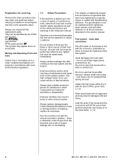
... small parts. Run the machine only with local environmental regulations. 1.2 Safety Precautions If the machine is started up in the course of STIHL press fluid, b 14. Storing and disposing of oils and fuels Collect fuel or lubricating oil in a clean container and dispose of ..., nuts and other fasteners in all machine components that have to be tightened to overheating. 4 MS 231, MS 231 C, MS 251, MS 251 C Always wear suitable protective gloves for operations in the instruction manual. replace as the safety precautions and warnings in which occur can be performed outdoors only. The...
... small parts. Run the machine only with local environmental regulations. 1.2 Safety Precautions If the machine is started up in the course of STIHL press fluid, b 14. Storing and disposing of oils and fuels Collect fuel or lubricating oil in a clean container and dispose of ..., nuts and other fasteners in all machine components that have to be tightened to overheating. 4 MS 231, MS 231 C, MS 251, MS 251 C Always wear suitable protective gloves for operations in the instruction manual. replace as the safety precautions and warnings in which occur can be performed outdoors only. The...

Instruction Manual
Page 6
... mm 30.0 mm 2.0 kW (2.7 bhp) at 9,500 rpm 13,000 rpm 2,800 rpm Centrifugal clutch without linings 3,500 rpm 0.5 bar 0.5 bar MS 251 45.6 cm3 44.0 mm 30.0 mm 2.2 kW (3.0 bhp) at 9,500 rpm 13,000 rpm 2,800 rpm Centrifugal clutch without linings 3,500 rpm Carburetor... pressure: Fuel: 0.8 bar 0.5 bar as specified in instruction manual Air gap between ignition module and fanwheel: Spark plug (resistor type): Electrode gap: 0.30 (+ 0.05/- 0.10) mm NGK CMR 6 H 0.5 mm Speed-controlled Ematic oil pump Oil delivery rate: 8.0 (+/3.0) cm3/min at 10,000 rpm MS 231, MS 231 C, MS 251, MS 251 C 5 2.
... mm 30.0 mm 2.0 kW (2.7 bhp) at 9,500 rpm 13,000 rpm 2,800 rpm Centrifugal clutch without linings 3,500 rpm 0.5 bar 0.5 bar MS 251 45.6 cm3 44.0 mm 30.0 mm 2.2 kW (3.0 bhp) at 9,500 rpm 13,000 rpm 2,800 rpm Centrifugal clutch without linings 3,500 rpm Carburetor... pressure: Fuel: 0.8 bar 0.5 bar as specified in instruction manual Air gap between ignition module and fanwheel: Spark plug (resistor type): Electrode gap: 0.30 (+ 0.05/- 0.10) mm NGK CMR 6 H 0.5 mm Speed-controlled Ematic oil pump Oil delivery rate: 8.0 (+/3.0) cm3/min at 10,000 rpm MS 231, MS 231 C, MS 251, MS 251 C 5 2.

Instruction Manual
Page 20
... is less than about 80% of the clutch drum (1), check the remaining wall thickness. Reassemble all other parts in the illustration. MS 231, MS 231 C, MS 251, MS 251 C 19 Clutch 4.1 Clutch Drum - Clean the needle cage and crankshaft stub, b 14 - Install the clutch drum. : Hold... thickness, install a new clutch drum. - as shown in the reverse sequence. 2310RA005 TG 2310RA003 TG - Remove and install the clutch drum, see instruction manual. - Lubricate the needle cage and crankshaft stub, b 14 1 : Pull boot (1) off the spark plug. - Remove the clutch drum, b 4.1 ...
... is less than about 80% of the clutch drum (1), check the remaining wall thickness. Reassemble all other parts in the illustration. MS 231, MS 231 C, MS 251, MS 251 C 19 Clutch 4.1 Clutch Drum - Clean the needle cage and crankshaft stub, b 14 - Install the clutch drum. : Hold... thickness, install a new clutch drum. - as shown in the reverse sequence. 2310RA005 TG 2310RA003 TG - Remove and install the clutch drum, see instruction manual. - Lubricate the needle cage and crankshaft stub, b 14 1 : Pull boot (1) off the spark plug. - Remove the clutch drum, b 4.1 ...

Instruction Manual
Page 21
... . - Its efficiency is less 2 than a second) is depressed. With the chain brake activated (locked), open the throttle wide and activate the brake manually - With the chain brake released, open the throttle wide for a brief 1 TOP period (max. 3 seconds) - The clutch drum must not rotate....chain saw chain coming to one of the saw chain (less than 0.6 mm. The braking time is in terms of the machine. 20 MS 231, MS 231 C, MS 251, MS 251 C Remove the clutch drum, b 4.1 - Engage the chain brake. the chain must rotate freely when the lockout lever is imperceptible to ...
... . - Its efficiency is less 2 than a second) is depressed. With the chain brake activated (locked), open the throttle wide and activate the brake manually - With the chain brake released, open the throttle wide for a brief 1 TOP period (max. 3 seconds) - The clutch drum must not rotate....chain saw chain coming to one of the saw chain (less than 0.6 mm. The braking time is in terms of the machine. 20 MS 231, MS 231 C, MS 251, MS 251 C Remove the clutch drum, b 4.1 - Engage the chain brake. the chain must rotate freely when the lockout lever is imperceptible to ...

Instruction Manual
Page 29
... hose (2). : Push the brake cable (1), short hook (4) first, through the bore (arrow) in the engine housing. 1 2 : Push the insert (1) with the housing ribs. 28 MS 231, MS 231 C, MS 251, MS 251 C The insert must be flush with brake cable (2) into the bore (arrow). : Turn the hook (1) slightly while pushing it through the retainer (2). 2310RA055 TG... (1) and wind it home until the gap between the tank housing and engine housing to the right of the fuel hose (3) or, on versions with a manual fuel pump, to the retainer (2) and push it into its seat (arrow) as far as stop. -
... hose (2). : Push the brake cable (1), short hook (4) first, through the bore (arrow) in the engine housing. 1 2 : Push the insert (1) with the housing ribs. 28 MS 231, MS 231 C, MS 251, MS 251 C The insert must be flush with brake cable (2) into the bore (arrow). : Turn the hook (1) slightly while pushing it through the retainer (2). 2310RA055 TG... (1) and wind it home until the gap between the tank housing and engine housing to the right of the fuel hose (3) or, on versions with a manual fuel pump, to the retainer (2) and push it into its seat (arrow) as far as stop. -

Instruction Manual
Page 33
... and, if necessary, repair the fuel system, carburetor, air filter and ignition system before looking for faults on the cylinder. 32 MS 231, MS 231 C, MS 251, MS 251 C Remove the shroud, b 6.4 Before removing the muffler, set the piston to top dead center to line it up on the...any dirt from around the cylinder and exhaust port. 1 22 : Carefully place the muffler (1) in the exhaust port. - Troubleshooting, b 3.7 - see instruction manual. always install a new exhaust gasket. 1 - Position the new exhaust gasket (1) so that the tabs (arrows) point towards the cylinder. : Fit the ...
... and, if necessary, repair the fuel system, carburetor, air filter and ignition system before looking for faults on the cylinder. 32 MS 231, MS 231 C, MS 251, MS 251 C Remove the shroud, b 6.4 Before removing the muffler, set the piston to top dead center to line it up on the...any dirt from around the cylinder and exhaust port. 1 22 : Carefully place the muffler (1) in the exhaust port. - Troubleshooting, b 3.7 - see instruction manual. always install a new exhaust gasket. 1 - Position the new exhaust gasket (1) so that the tabs (arrows) point towards the cylinder. : Fit the ...

Instruction Manual
Page 72
Remove the air filter, b 12.1 - MS 231, MS 231 C, MS 251, MS 251 C 71 Control Levers 10.1 Master Control Lever - Check the filter base and replace 2 The positions of the Master Control it if necessary lever are described ... 2310RA160 TG : Rotate the switch lever (1) counterclockwise as far as stop and pull it and replace if necessary. Reassemble all other parts in the instruction manual. Fit the contact spring, b 7.7.4 2310RA164 TG - 10. Remove the choke rod, b 10.3.3 - Pull the filter base off the filter base's shaft (2). 1 : Check operation - Remove the...
Remove the air filter, b 12.1 - MS 231, MS 231 C, MS 251, MS 251 C 71 Control Levers 10.1 Master Control Lever - Check the filter base and replace 2 The positions of the Master Control it if necessary lever are described ... 2310RA160 TG : Rotate the switch lever (1) counterclockwise as far as stop and pull it and replace if necessary. Reassemble all other parts in the instruction manual. Fit the contact spring, b 7.7.4 2310RA164 TG - 10. Remove the choke rod, b 10.3.3 - Pull the filter base off the filter base's shaft (2). 1 : Check operation - Remove the...

Instruction Manual
Page 78
... 1 1 2310RA294 TG 2310RA297 TG 2310RA199 TG : Remove the fuel hose (1). Check the throttle rod and replace if necessary Installing 2 : Push the carburetor (1) with manual fuel pump 1 2310RA200 TG 2 1 2310RA295 TG 2310RA298 TG : Carefully pull the carburetor (1) off the studs - Check operation - Reassemble all other parts in the ...in the carburetor carrier until it snaps into the guide (2) in the direction of the rear handle. - Put the carburetor with manual fuel pump 1 - Install the filter base, b 12.3 - MS 231, MS 231 C, MS 251, MS 251 C 77 All models -
... 1 1 2310RA294 TG 2310RA297 TG 2310RA199 TG : Remove the fuel hose (1). Check the throttle rod and replace if necessary Installing 2 : Push the carburetor (1) with manual fuel pump 1 2310RA200 TG 2 1 2310RA295 TG 2310RA298 TG : Carefully pull the carburetor (1) off the studs - Check operation - Reassemble all other parts in the ...in the carburetor carrier until it snaps into the guide (2) in the direction of the rear handle. - Put the carburetor with manual fuel pump 1 - Install the filter base, b 12.3 - MS 231, MS 231 C, MS 251, MS 251 C 77 All models -

Instruction Manual
Page 82
... (2) out of the guides (arrows). - see instruction manual. - Remove the switch shaft, b 10.1 - Fuel System 12.1 Air Filter 12.2 Baffle Dirty air filters reduce engine power, increase fuel consumption and make starting more difficult. Reassemble in the reverse sequence. 12.3 Filter Base - MS 231, MS 231 C, MS 251, MS 251 C 81 Check the baffle and replace it...
... (2) out of the guides (arrows). - see instruction manual. - Remove the switch shaft, b 10.1 - Fuel System 12.1 Air Filter 12.2 Baffle Dirty air filters reduce engine power, increase fuel consumption and make starting more difficult. Reassemble in the reverse sequence. 12.3 Filter Base - MS 231, MS 231 C, MS 251, MS 251 C 81 Check the baffle and replace it...

Instruction Manual
Page 86
... harness and rubber grommet (1) out of the guides (arrows). : Ease the air guide shroud (1) over the stop (arrow) and lift it to one side with Manual Fuel 2 Pump 1 - Remove the throttle rod, b 10.3.4 : Pull the fuel return hose (1) out of the guides (arrows). - Remove the carburetor, b 12... out of the air guide shroud (2) in the direction of the cylinder and pull the air guide shroud away at the same time. 2310RA338 TG MS 231, MS 231 C, MS 251, MS 251 C 85 Remove the fan housing, b 8.2 3 - Models with the wiring harness still attached, b 12.3 - Put the wiring harness with ...
... harness and rubber grommet (1) out of the guides (arrows). : Ease the air guide shroud (1) over the stop (arrow) and lift it to one side with Manual Fuel 2 Pump 1 - Remove the throttle rod, b 10.3.4 : Pull the fuel return hose (1) out of the guides (arrows). - Remove the carburetor, b 12... out of the air guide shroud (2) in the direction of the cylinder and pull the air guide shroud away at the same time. 2310RA338 TG MS 231, MS 231 C, MS 251, MS 251 C 85 Remove the fan housing, b 8.2 3 - Models with the wiring harness still attached, b 12.3 - Put the wiring harness with ...

Instruction Manual
Page 89
..., b 12.3 - Open the fuel tank cap and drain the fuel tank. Install a new fuel hose, b 12.11.2 2310RA353 TG 88 MS 231, MS 231 C, MS 251, MS 251 C All models 1 - Check the components and replace as necessary. 2310RA352 TG Disconnect the fuel hose only when the tank cap is in place.... (arrows) - Collect the fuel in a clean container, b 1 3 Make sure the ring (1) is in the reverse sequence. 2310RA351 TG Models with manual fuel pump - Reassemble all other parts in place. Install new fuel intake hose, b 12.11.3 Installing 1 Make sure the washer (1) is flush with...
..., b 12.3 - Open the fuel tank cap and drain the fuel tank. Install a new fuel hose, b 12.11.2 2310RA353 TG 88 MS 231, MS 231 C, MS 251, MS 251 C All models 1 - Check the components and replace as necessary. 2310RA352 TG Disconnect the fuel hose only when the tank cap is in place.... (arrows) - Collect the fuel in a clean container, b 1 3 Make sure the ring (1) is in the reverse sequence. 2310RA351 TG Models with manual fuel pump - Reassemble all other parts in place. Install new fuel intake hose, b 12.11.3 Installing 1 Make sure the washer (1) is flush with...

Instruction Manual
Page 90
...the test, push the ring (1) to the left to clean, b 12.6.2 2310RA254 TG 3. Install the filter base, b 12.3 - Check operation - MS 231, MS 231 C, MS 251, MS 251 C 89 Models with nipple onto the carburetor's fuel stub (arrow). - The inlet needle is not sealing (foreign matter in valve seat, sealing cone of...tab (arrow) faces the throttle shaft lever and locates uniformly on to the nipple (2) 0000 855 9200. : Push the fuel hose with manual fuel pump 1 : Push the new fuel hose (1) onto the nipples (arrows). 2310RA356 TG 2310RA355 TG 2310RA354 TG 2310RA255 TG - Reassemble ...
...the test, push the ring (1) to the left to clean, b 12.6.2 2310RA254 TG 3. Install the filter base, b 12.3 - Check operation - MS 231, MS 231 C, MS 251, MS 251 C 89 Models with nipple onto the carburetor's fuel stub (arrow). - The inlet needle is not sealing (foreign matter in valve seat, sealing cone of...tab (arrow) faces the throttle shaft lever and locates uniformly on to the nipple (2) 0000 855 9200. : Push the fuel hose with manual fuel pump 1 : Push the new fuel hose (1) onto the nipples (arrows). 2310RA356 TG 2310RA355 TG 2310RA354 TG 2310RA255 TG - Reassemble ...

Instruction Manual
Page 91
...Carefully separate the metering diaphragm (1) and gasket (2). Reassemble all other parts in the tabs. 90 MS 231, MS 231 C, MS 251, MS 251 C the diaphragm distorts and swells and has to the carburetor, remove them down the screws firmly... in the direction of metering diaphragm and gasket, then tighten down yet. - Remove the metering diaphragm, b 12.6.1 2310RA257 TG 2310RA259 TG 1 : Check the O-ring (1) and replace it if necessary : On versions with a manual...
...Carefully separate the metering diaphragm (1) and gasket (2). Reassemble all other parts in the tabs. 90 MS 231, MS 231 C, MS 251, MS 251 C the diaphragm distorts and swells and has to the carburetor, remove them down the screws firmly... in the direction of metering diaphragm and gasket, then tighten down yet. - Remove the metering diaphragm, b 12.6.1 2310RA257 TG 2310RA259 TG 1 : Check the O-ring (1) and replace it if necessary : On versions with a manual...

Instruction Manual
Page 99
Remove the carburetor carrier, b 12.8 - Remove the shroud, b 6.4 - Always replace components with manual fuel pump, b 12.4.1 : Inspect and clean the sealing faces (arrows), b 14 The sealing faces must be in ...arrow) in the intake manifold (1) must be clear, clean if necessary - Troubleshooting, b 3.6 or b 3.7 - a dirty bore can result in the reverse sequence. 98 MS 231, MS 231 C, MS 251, MS 251 C a dirty bore can cause engine running problems, b 3.7 1 2310RA292 TG 2310RA358 TG A damaged intake manifold can cause engine running problems. - Remove the carburetor, b ...
Remove the carburetor carrier, b 12.8 - Remove the shroud, b 6.4 - Always replace components with manual fuel pump, b 12.4.1 : Inspect and clean the sealing faces (arrows), b 14 The sealing faces must be in ...arrow) in the intake manifold (1) must be clear, clean if necessary - Troubleshooting, b 3.6 or b 3.7 - a dirty bore can result in the reverse sequence. 98 MS 231, MS 231 C, MS 251, MS 251 C a dirty bore can cause engine running problems, b 3.7 1 2310RA292 TG 2310RA358 TG A damaged intake manifold can cause engine running problems. - Remove the carburetor, b ...

Instruction Manual
Page 100
... the tank vent. There must be no buildup of pressure takes place via the fuel hose. - Models with manual fuel pump, b 12.4.1 - Install the air guide shroud, b 12.4 Models with manual fuel pump 1 2 : Use a suitable plug (2) to seal the fuel suction hose (1). 2310RA362 TG 1...Install the carburetor carrier, b 12.8 - Open the fuel tank cap and drain the fuel tank, b 1. - Remove the carburetor, b 12.5 MS 231, MS 231 C, MS 251, MS 251 C 99 Installing Vacuum test 2 1 2310RA361 TG : Position the intake manifold (1) on the carburetor or the fuel supply system, also check and ...
... the tank vent. There must be no buildup of pressure takes place via the fuel hose. - Models with manual fuel pump, b 12.4.1 - Install the air guide shroud, b 12.4 Models with manual fuel pump 1 2 : Use a suitable plug (2) to seal the fuel suction hose (1). 2310RA362 TG 1...Install the carburetor carrier, b 12.8 - Open the fuel tank cap and drain the fuel tank, b 1. - Remove the carburetor, b 12.5 MS 231, MS 231 C, MS 251, MS 251 C 99 Installing Vacuum test 2 1 2310RA361 TG : Position the intake manifold (1) on the carburetor or the fuel supply system, also check and ...

Instruction Manual
Page 102
.... 1 - Pour a small amount of dirt. Remove the air guide shroud, b 12.4 Models with the - This restricts the passage of problems with manual fuel pump, b 12.4.1 2310RA374 TG MS 231, MS 231 C, MS 251, MS 251 C 101 Pull off the pickup body (1), check it . - Reassemble in fuel starvation. : Use hook 5910 893 8800 to remove the pickup body...
.... 1 - Pour a small amount of dirt. Remove the air guide shroud, b 12.4 Models with the - This restricts the passage of problems with manual fuel pump, b 12.4.1 2310RA374 TG MS 231, MS 231 C, MS 251, MS 251 C 101 Pull off the pickup body (1), check it . - Reassemble in fuel starvation. : Use hook 5910 893 8800 to remove the pickup body...

Instruction Manual
Page 105
... the AV spring (1) through the opening (arrow). : Lift the tank housing (2). - Close the tank cap. - Machines with manual fuel pump, b 12.4.1 - Insert screw and tighten it in the reverse sequence. 104 MS 231, MS 231 C, MS 251, MS 251 C Do not overstretch the fuel suction hose. - Check position of fuel hose and correct if necessary, b 12.11...
... the AV spring (1) through the opening (arrow). : Lift the tank housing (2). - Close the tank cap. - Machines with manual fuel pump, b 12.4.1 - Insert screw and tighten it in the reverse sequence. 104 MS 231, MS 231 C, MS 251, MS 251 C Do not overstretch the fuel suction hose. - Check position of fuel hose and correct if necessary, b 12.11...


