
User Guide
Page 1
und Bedienungsanleitung 3CBLSF26 3CBLSF26PWR 3CBLSF50 www.3Com.com Part No. 10016622 Published May 2008 Baseline Switch 2226-SFP Plus Baseline Switch 2426-PWR Plus Baseline Switch 2250-SFP Plus Installation and User Guide Installations-
und Bedienungsanleitung 3CBLSF26 3CBLSF26PWR 3CBLSF50 www.3Com.com Part No. 10016622 Published May 2008 Baseline Switch 2226-SFP Plus Baseline Switch 2426-PWR Plus Baseline Switch 2250-SFP Plus Installation and User Guide Installations-
User Guide
Page 3
CONTENTS ABOUT THIS GUIDE Conventions 7 Documentation Comments 8 Product Registration 8 1 INTRODUCING THE BASELINE SWITCH Overview of the Baseline Switch 9 Features and Capabilities 9 Autosensing of MDI/MDIX Connections 9 Autonegotiating 10/100 Mbps Ports 9 Power-over-Ethernet ... Navigating the Web Interface 28 Menu 28 Buttons 31 Port Status 31 Accessing the Switch using the 3Com Switch Detect Application 31 Running the 3Com Switch Detect Application 32 4 CONFIGURING THE SWITCH FROM THE WEB INTERFACE Configuration Overview 35 Device Summary Information 35 Administration Settings 37 ...
CONTENTS ABOUT THIS GUIDE Conventions 7 Documentation Comments 8 Product Registration 8 1 INTRODUCING THE BASELINE SWITCH Overview of the Baseline Switch 9 Features and Capabilities 9 Autosensing of MDI/MDIX Connections 9 Autonegotiating 10/100 Mbps Ports 9 Power-over-Ethernet ... Navigating the Web Interface 28 Menu 28 Buttons 31 Port Status 31 Accessing the Switch using the 3Com Switch Detect Application 31 Running the 3Com Switch Detect Application 32 4 CONFIGURING THE SWITCH FROM THE WEB INTERFACE Configuration Overview 35 Device Summary Information 35 Administration Settings 37 ...
User Guide
Page 7
...this guide. It covers the following switches: Baseline Switch 2226-SFP Plus (3CBLSF26) Baseline Switch 2426-PWR Plus (3CBLSF26PWR) Baseline Switch 2250-SFP Plus (3CBLSF50) Unless noted otherwise, the features, specifications and procedures described hereafter are shipped with your 3Com Switch and perform initial management configurations. consequently... and setting up network equipment; Where features vary significantly between the switches, examples are based on the 3Com World Wide Web site: www.3Com.com Conventions Table 1 and Table 2 list conventions that alerts you...
...this guide. It covers the following switches: Baseline Switch 2226-SFP Plus (3CBLSF26) Baseline Switch 2426-PWR Plus (3CBLSF26PWR) Baseline Switch 2250-SFP Plus (3CBLSF50) Unless noted otherwise, the features, specifications and procedures described hereafter are shipped with your 3Com Switch and perform initial management configurations. consequently... and setting up network equipment; Where features vary significantly between the switches, examples are based on the 3Com World Wide Web site: www.3Com.com Conventions Table 1 and Table 2 list conventions that alerts you...
User Guide
Page 8
...are very important to -date information on the 3Com Web site to receive up-to us : ■ Document title ■ Document part number (on the title page) ■ Page number (if appropriate) Example: ■ Baseline Switch 2426-PWR Plus User Guide ■ Part number: 10016622 ...■ Page 25 Please note that we can now register your Baseline Switch on your product: http://esupport.3Com.com Product Registration You can only respond to your network supplier...
...are very important to -date information on the 3Com Web site to receive up-to us : ■ Document title ■ Document part number (on the title page) ■ Page number (if appropriate) Example: ■ Baseline Switch 2426-PWR Plus User Guide ■ Part number: 10016622 ...■ Page 25 Please note that we can now register your Baseline Switch on your product: http://esupport.3Com.com Product Registration You can only respond to your network supplier...
User Guide
Page 9
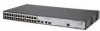
... network devices to each port using either a normal straight-through TP (twisted pair) cable or a 'crossover' TP cable. It also identifies the contents of the 3Com Baseline Switch 2226-SFP Plus, 3Com Baseline Switch 2426-PWR Plus, and 3Com Baseline Switch 2250-SFP Plus. Any port can autosense both medium dependent interface (MDI) and medium dependent interface crossover (MDIX) connections.
... network devices to each port using either a normal straight-through TP (twisted pair) cable or a 'crossover' TP cable. It also identifies the contents of the 3Com Baseline Switch 2226-SFP Plus, 3Com Baseline Switch 2426-PWR Plus, and 3Com Baseline Switch 2250-SFP Plus. Any port can autosense both medium dependent interface (MDI) and medium dependent interface crossover (MDIX) connections.

User Guide
Page 10
10 INTRODUCING THE BASELINE SWITCH 10/100 Mbps ports can operate in any combination. Any 802.3af compliant device attached to provide connectivity between the PD and the Switch 2426-PWR), subject to numbered sections in these diagrams refer to the maximum power budget available. Gigabit Combo Ports (RJ-45...is disabled. The numbers in "Front Panel" on page 11 and "Rear Panel" on page 15. Power-over-Ethernet Capability The Switch 2426-PWR Plus (3CBLSF26PWR) provides 24 front panel RJ-45 ports that support the IEEE 802.3af Power-over the Ethernet cable without requiring its own...
10 INTRODUCING THE BASELINE SWITCH 10/100 Mbps ports can operate in any combination. Any 802.3af compliant device attached to provide connectivity between the PD and the Switch 2426-PWR), subject to numbered sections in these diagrams refer to the maximum power budget available. Gigabit Combo Ports (RJ-45...is disabled. The numbers in "Front Panel" on page 11 and "Rear Panel" on page 15. Power-over-Ethernet Capability The Switch 2426-PWR Plus (3CBLSF26PWR) provides 24 front panel RJ-45 ports that support the IEEE 802.3af Power-over the Ethernet cable without requiring its own...
User Guide
Page 11
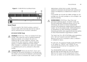
... WARNHINWEIS: RJ-45-Porte. Entweder geschützte oder ungeschützte Buchsen dürfen an diese Datensteckdosen angeschlossen werden. The 3CBLSF26PWR Switch also supports IEEE 802.3af-2003 standard (802.3af) and pre-standard P802.3at DTE Power via MDI Enhancements (PoE+). Nur RJ-...or network telephones to either a 10BASE-T, or 100BASE-TX device. Figure 3 3CBLSF50 Front and Rear Panels Front Panel The front panel of the Switch contains a series of indicator lights (LEDs) that help describe the state of the connected device. Sie dürfen weder wie normale traditionelle ...
... WARNHINWEIS: RJ-45-Porte. Entweder geschützte oder ungeschützte Buchsen dürfen an diese Datensteckdosen angeschlossen werden. The 3CBLSF26PWR Switch also supports IEEE 802.3af-2003 standard (802.3af) and pre-standard P802.3at DTE Power via MDI Enhancements (PoE+). Nur RJ-...or network telephones to either a 10BASE-T, or 100BASE-TX device. Figure 3 3CBLSF50 Front and Rear Panels Front Panel The front panel of the Switch contains a series of indicator lights (LEDs) that help describe the state of the connected device. Sie dürfen weder wie normale traditionelle ...
User Guide
Page 12
... com port connection parameters in any combination. This offers you the flexibility of using SFP transceivers to provide connectivity between the PD and the Switch 2426-PWR, subject to create a high-capacity aggregated link backbone connection. The SFP port supports full duplex mode only. When an SFP port is ... the associated RJ-45 port of the same number. If the link connection on the SFP port is the SFP port. 12 INTRODUCING THE BASELINE SWITCH network devices, such as follows: ■ Com port: Choose based on the computer serial port to the Console Port, you can be ...
... com port connection parameters in any combination. This offers you the flexibility of using SFP transceivers to provide connectivity between the PD and the Switch 2426-PWR, subject to create a high-capacity aggregated link backbone connection. The SFP port supports full duplex mode only. When an SFP port is ... the associated RJ-45 port of the same number. If the link connection on the SFP port is the SFP port. 12 INTRODUCING THE BASELINE SWITCH network devices, such as follows: ■ Com port: Choose based on the computer serial port to the Console Port, you can be ...

User Guide
Page 14
...) fiber cables are being received or transmitted on . ■ Check that the attached device is powered on the port at 1000 Mbps. 14 INTRODUCING THE BASELINE SWITCH 1000BASE-T Mode Table 3 1000BASE-T Link/Activity Status LEDs Link/Activity Meaning Green The link is faulty.
...) fiber cables are being received or transmitted on . ■ Check that the attached device is powered on the port at 1000 Mbps. 14 INTRODUCING THE BASELINE SWITCH 1000BASE-T Mode Table 3 1000BASE-T Link/Activity Status LEDs Link/Activity Meaning Green The link is faulty.

User Guide
Page 15
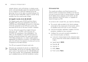
...the power status of the lower unit. If the unit is not receiving power. ■ Check that the pads locate within the recesses of the Switch. Rear Panel The rear panel of the unit. Yellow Internal power, POST, or loopback test has failed. Place the unit on and ready for use... the power cord that is a valid link on the underside of the Switch contains the power supply socket. (9) Power Socket The Switch automatically adjusts to rack mount the unit. Table 6 SFP Mode SFP/Duplex Status LEDs SFP/Duplex Meaning Green The SFP ...
...the power status of the lower unit. If the unit is not receiving power. ■ Check that the pads locate within the recesses of the Switch. Rear Panel The rear panel of the unit. Yellow Internal power, POST, or loopback test has failed. Place the unit on and ready for use... the power cord that is a valid link on the underside of the Switch contains the power supply socket. (9) Power Socket The Switch automatically adjusts to rack mount the unit. Table 6 SFP Mode SFP/Duplex Status LEDs SFP/Duplex Meaning Green The SFP ...
User Guide
Page 16
If any of the above items are damaged or missing, contact your Switch package is powered from the AC supply. 16 INTRODUCING THE BASELINE SWITCH Package Contents Before installing and using the Switch, verify that your 3Com network supplier immediately. The Switch comes with: ■ One power cord ■ One console cable ■ Four standard height, self-adhesive rubber pads ■ One mounting kit (part number 123193-104) ■ Installation CD ■ This User Guide ■ Warranty flyer The Switch is complete.
If any of the above items are damaged or missing, contact your Switch package is powered from the AC supply. 16 INTRODUCING THE BASELINE SWITCH Package Contents Before installing and using the Switch, verify that your 3Com network supplier immediately. The Switch comes with: ■ One power cord ■ One console cable ■ Four standard height, self-adhesive rubber pads ■ One mounting kit (part number 123193-104) ■ Installation CD ■ This User Guide ■ Warranty flyer The Switch is complete.
User Guide
Page 17
... for this product. 2 INSTALLING THE SWITCH This chapter contains information that was included with this would be: Informações de Segurança e Regulatórias da Famila de Switches 3Com) incluido no site da 3Com: www.3Com.com Viktig säkerhets information Vä...;nligen hänför till säkerhets informationen som är inkluderad med denna produkt i 3Com Switch Family Safety and Regulatory Information manualen. It covers ...
... for this product. 2 INSTALLING THE SWITCH This chapter contains information that was included with this would be: Informações de Segurança e Regulatórias da Famila de Switches 3Com) incluido no site da 3Com: www.3Com.com Viktig säkerhets information Vä...;nligen hänför till säkerhets informationen som är inkluderad med denna produkt i 3Com Switch Family Safety and Regulatory Information manualen. It covers ...
User Guide
Page 18
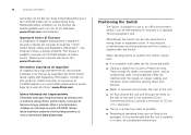
...electrical noise. Importante Avviso di Sicurezza Vi preghiamo di leggere attentamente e seguire le istruzioni indicate nel manuale di sicurezza "3Com Switch Family Safety and Regulatory Information", che troverete incluso a questo prodotto. Sie können diese Sicherheitsanleitung auf der CD-ROM...żliwość pobrania instrukcji bezpośrednio ze strony internetowej www.3Com.com Positioning the Switch The Switch is accessible and cables can interfere with the Switch. Alternatively, the Switch can be exceeded. Wraz z prze łącznikiem znajduje sie instrukcja na...
...electrical noise. Importante Avviso di Sicurezza Vi preghiamo di leggere attentamente e seguire le istruzioni indicate nel manuale di sicurezza "3Com Switch Family Safety and Regulatory Information", che troverete incluso a questo prodotto. Sie können diese Sicherheitsanleitung auf der CD-ROM...żliwość pobrania instrukcji bezpośrednio ze strony internetowej www.3Com.com Positioning the Switch The Switch is accessible and cables can interfere with the Switch. Alternatively, the Switch can be exceeded. Wraz z prze łącznikiem znajduje sie instrukcja na...
User Guide
Page 19
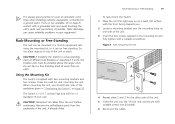
... the unit, if already fitted. Remove the self-adhesive pads from the unit before continuing. Rack-Mounting or Free-Standing 19 To rack-mount the Switch: 1 Place the unit the right way up on a hard, flat surface with suitable screws (not provided). 6 Reconnect the cables. If one side of the ...unit. 5 Insert the unit into the 19-inch rack and secure with the front facing towards you should take note of different size Baseline or Superstack 3 units, the smaller units must be free standing. These are used for the other side of the unit. 3 Insert the two screws supplied...
... the unit, if already fitted. Remove the self-adhesive pads from the unit before continuing. Rack-Mounting or Free-Standing 19 To rack-mount the Switch: 1 Place the unit the right way up on a hard, flat surface with suitable screws (not provided). 6 Reconnect the cables. If one side of the ...unit. 5 Insert the unit into the 19-inch rack and secure with the front facing towards you should take note of different size Baseline or Superstack 3 units, the smaller units must be free standing. These are used for the other side of the unit. 3 Insert the two screws supplied...

User Guide
Page 21
...on page 15 for assistance. If these do not resolve the issue: ■ Check the 3Com Knowledgebase for the Power LED after you power on the Switch, it on page 75. To power on the Switch: 1 Plug the power cord into a power outlet. During POST, the Power LED on... can happen if a port or ports fail when the Switch was successfully completed. ■ Reset the Switch. CAUTION: Resetting the Switch to "(9) Power Socket" on . To visit the 3Com Knowledgebase Web site, start your Web browser, and then enter http://knowledgebase.3Com.com. ■ Contact your settings. Refer to its factory...
...on page 15 for assistance. If these do not resolve the issue: ■ Check the 3Com Knowledgebase for the Power LED after you power on the Switch, it on page 75. To power on the Switch: 1 Plug the power cord into a power outlet. During POST, the Power LED on... can happen if a port or ports fail when the Switch was successfully completed. ■ Reset the Switch. CAUTION: Resetting the Switch to "(9) Power Socket" on . To visit the 3Com Knowledgebase Web site, start your Web browser, and then enter http://knowledgebase.3Com.com. ■ Contact your settings. Refer to its factory...

User Guide
Page 22
...describe how to insert an SFP transceiver into any SFP port without having to multimode fiber using 3Com SFPs in the upright position). If you and the product label is closed (in the Switch. To activate the SFP port: 1 Hold the transceiver so that the fiber connector is ... type: ■ 1000BASE-SX SFP transceiver Use this transceiver to connect the Switch directly to a multimode fiber-optic cable. ■ 1000BASE-LX SFP transceiver Use this URL into your Internet browser: http://www.3Com.com 3Com recommends using a conditioned launch cable. You can remove them from and insert ...
...describe how to insert an SFP transceiver into any SFP port without having to multimode fiber using 3Com SFPs in the upright position). If you and the product label is closed (in the Switch. To activate the SFP port: 1 Hold the transceiver so that the fiber connector is ... type: ■ 1000BASE-SX SFP transceiver Use this transceiver to connect the Switch directly to a multimode fiber-optic cable. ■ 1000BASE-LX SFP transceiver Use this URL into your Internet browser: http://www.3Com.com 3Com recommends using a conditioned launch cable. You can remove them from and insert ...

User Guide
Page 23
... 7 Check the Module Active LEDs on the transceiver. Removing an SFP Transceiver Removing an SFP transceiver does not require powering off the Switch. Performing Spot Checks At frequent intervals, you to when there will be properly inserted only one way. any problems can be least ...effect on users. 3Com recommends periodically checking the items listed in Table 9. The SFP transceiver should visually check the Switch. To remove an SFP transceiver: 1 Disconnect the cable from the transceiver. 2 Move the wire...
... 7 Check the Module Active LEDs on the transceiver. Removing an SFP Transceiver Removing an SFP transceiver does not require powering off the Switch. Performing Spot Checks At frequent intervals, you to when there will be properly inserted only one way. any problems can be least ...effect on users. 3Com recommends periodically checking the items listed in Table 9. The SFP transceiver should visually check the Switch. To remove an SFP transceiver: 1 Disconnect the cable from the transceiver. 2 Move the wire...

User Guide
Page 24
The fan is operating by listening to the unit. Cooling fan (3CBLSF26PWR only) Where possible, check that no cables are pulled taut. If you experience any problems operating the Switch, refer to the front right hand side of the unit (when viewed from the front). 24 INSTALLING THE SWITCH Table 9 Items to Check Cabling Check that all external cabling connections are secure and that the cooling fan is fitted near to "Troubleshooting" on page 75.
The fan is operating by listening to the unit. Cooling fan (3CBLSF26PWR only) Where possible, check that no cables are pulled taut. If you experience any problems operating the Switch, refer to the front right hand side of the unit (when viewed from the front). 24 INSTALLING THE SWITCH Table 9 Items to Check Cabling Check that all external cabling connections are secure and that the cooling fan is fitted near to "Troubleshooting" on page 75.
User Guide
Page 25
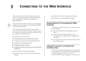
...■ Navigating the Web Interface ■ Accessing the Switch using the Discovery application. The IP addressing mode of the following: ■ The console cable that was supplied with your Switch. ■ The 3Com Switch Detect application, that is included on the CD-ROM...Administration/IP Setup on the Web interface. This chapter provides information on how to gain access to the Web interface using the 3Com Switch Detect Application The Switch support the following browsers: ■ Microsoft Internet Explorer (V6.0 and subsequent releases) ■ Mozilla Firefox (V2.0 and ...
...■ Navigating the Web Interface ■ Accessing the Switch using the Discovery application. The IP addressing mode of the following: ■ The console cable that was supplied with your Switch. ■ The 3Com Switch Detect application, that is included on the CD-ROM...Administration/IP Setup on the Web interface. This chapter provides information on how to gain access to the Web interface using the 3Com Switch Detect Application The Switch support the following browsers: ■ Microsoft Internet Explorer (V6.0 and subsequent releases) ■ Mozilla Firefox (V2.0 and ...
User Guide
Page 26
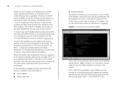
...address. This default IP address can change to a manually assigned IP address by a DHCP server, or to the top cover of the Switch. Connect the supplied console cable to the console socket, located on the label attached to manually assign one is available). Configure a suitable terminal... emulator application for the Switch. When the Switch has completed its power up to two minutes to try to a COM port on the console interface. Enter the username admin with...
...address. This default IP address can change to a manually assigned IP address by a DHCP server, or to the top cover of the Switch. Connect the supplied console cable to the console socket, located on the label attached to manually assign one is available). Configure a suitable terminal... emulator application for the Switch. When the Switch has completed its power up to two minutes to try to a COM port on the console interface. Enter the username admin with...


