
User Guide
Page 1
und Bedienungsanleitung 3CBLSF26 3CBLSF26PWR 3CBLSF50 www.3Com.com Part No. 10016622 Published May 2008 Baseline Switch 2226-SFP Plus Baseline Switch 2426-PWR Plus Baseline Switch 2250-SFP Plus Installation and User Guide Installations-
und Bedienungsanleitung 3CBLSF26 3CBLSF26PWR 3CBLSF50 www.3Com.com Part No. 10016622 Published May 2008 Baseline Switch 2226-SFP Plus Baseline Switch 2426-PWR Plus Baseline Switch 2250-SFP Plus Installation and User Guide Installations-
User Guide
Page 2
..., Inc. Intel and Pentium are vegetable-based with the product as translation, transformation, or adaptation) without written permission from 3Com Corporation. 3Com Corporation reserves the right to revise this documentation and to make any derivative work (such as a separate document, in any...recyclable and reusable content of Intel Corporation. The varnish is a registered trademark in the United States and other countries. 3Com and the 3Com logo are registered trademarks of the respective companies with only such rights as provided in DFAR 252.227-7015 (Nov 1995...
..., Inc. Intel and Pentium are vegetable-based with the product as translation, transformation, or adaptation) without written permission from 3Com Corporation. 3Com Corporation reserves the right to revise this documentation and to make any derivative work (such as a separate document, in any...recyclable and reusable content of Intel Corporation. The varnish is a registered trademark in the United States and other countries. 3Com and the 3Com logo are registered trademarks of the respective companies with only such rights as provided in DFAR 252.227-7015 (Nov 1995...
User Guide
Page 3
CONTENTS ABOUT THIS GUIDE Conventions 7 Documentation Comments 8 Product Registration 8 1 INTRODUCING THE BASELINE SWITCH Overview of the Baseline Switch 9 Features and Capabilities 9 Autosensing of MDI/MDIX Connections 9 Autonegotiating 10/100 Mbps Ports 9 Power-over-Ethernet Capability... Navigating the Web Interface 28 Menu 28 Buttons 31 Port Status 31 Accessing the Switch using the 3Com Switch Detect Application 31 Running the 3Com Switch Detect Application 32 4 CONFIGURING THE SWITCH FROM THE WEB INTERFACE Configuration Overview 35 Device Summary Information 35 Administration Settings 37...
CONTENTS ABOUT THIS GUIDE Conventions 7 Documentation Comments 8 Product Registration 8 1 INTRODUCING THE BASELINE SWITCH Overview of the Baseline Switch 9 Features and Capabilities 9 Autosensing of MDI/MDIX Connections 9 Autonegotiating 10/100 Mbps Ports 9 Power-over-Ethernet Capability... Navigating the Web Interface 28 Menu 28 Buttons 31 Port Status 31 Accessing the Switch using the 3Com Switch Detect Application 31 Running the 3Com Switch Detect Application 32 4 CONFIGURING THE SWITCH FROM THE WEB INTERFACE Configuration Overview 35 Device Summary Information 35 Administration Settings 37...
User Guide
Page 4
... Contact Us 80 B TECHNICAL INFORMATION 3CBLSF26 Related Standards 83 Environmental 83 Physical 83 Electrical 83 3CBLSF26PWR Related Standards 84 Environmental 84 Physical 84 Electrical 84 3CBLSF50 Related Standards 85 Environmental 85 Physical 85 Electrical 85 C PIN-OUTS Console Cable 87 Null Modem Cable 88
... Contact Us 80 B TECHNICAL INFORMATION 3CBLSF26 Related Standards 83 Environmental 83 Physical 83 Electrical 83 3CBLSF26PWR Related Standards 84 Environmental 84 Physical 84 Electrical 84 3CBLSF50 Related Standards 85 Environmental 85 Physical 85 Electrical 85 C PIN-OUTS Console Cable 87 Null Modem Cable 88
User Guide
Page 5
PC-AT Serial Cable 88 Modem Cable 88 Ethernet Port RJ-45 Pin Assignments 89 D 3COM CLI REFERENCE GUIDE Getting Started with the Command Line Interface 91 Console Port 91 Logging on to the CLI 91 Automatic Logout 92 Concurrent CLI Sessions 92 CLI Commands 92 ? 93 Ping 94 Summary 94 ipSetup 95 Upgrade 96 Initialize 97 Reboot 97 Logout 98 Password 98 REGULATORY NOTICES GLOSSARY INDEX
PC-AT Serial Cable 88 Modem Cable 88 Ethernet Port RJ-45 Pin Assignments 89 D 3COM CLI REFERENCE GUIDE Getting Started with the Command Line Interface 91 Console Port 91 Logging on to the CLI 91 Automatic Logout 92 Concurrent CLI Sessions 92 CLI Commands 92 ? 93 Ping 94 Summary 94 ipSetup 95 Upgrade 96 Initialize 97 Reboot 97 Logout 98 Password 98 REGULATORY NOTICES GLOSSARY INDEX
User Guide
Page 7
...switches, examples are based on the 3Com World Wide Web site: www.3Com.com Conventions Table 1 and Table 2 list conventions that alerts you to an application, system, or device Warning Information that are shared by those responsible for each. It covers the following switches: Baseline Switch 2226-SFP Plus (3CBLSF26) Baseline Switch 2426-PWR Plus (3CBLSF26PWR) Baseline Switch 2250-SFP Plus (3CBLSF50... of data or potential damage to potential loss of LANs (Local Area Networks). If release notes are shipped with your 3Com Switch and perform initial management configurations.
...switches, examples are based on the 3Com World Wide Web site: www.3Com.com Conventions Table 1 and Table 2 list conventions that alerts you to an application, system, or device Warning Information that are shared by those responsible for each. It covers the following switches: Baseline Switch 2226-SFP Plus (3CBLSF26) Baseline Switch 2426-PWR Plus (3CBLSF26PWR) Baseline Switch 2250-SFP Plus (3CBLSF50... of data or potential damage to potential loss of LANs (Local Area Networks). If release notes are shipped with your 3Com Switch and perform initial management configurations.
User Guide
Page 8
Examples: From the Help menu, select Contents. Please e-mail comments about 3Com product documentation at the place where it is defined in the text. ■ Identify menu names, menu commands, and software button names. 8 ABOUT THIS GUIDE...-PWR Plus User Guide ■ Part number: 10016622 ■ Page 25 Please note that we can now register your Baseline Switch on the 3Com Web site to receive up-to 3Com at: pddtechpubs_comments@3Com.com Please include the following information when contacting us . Documentation Comments Your suggestions are used to: ■ Emphasize a point. ■ ...
Examples: From the Help menu, select Contents. Please e-mail comments about 3Com product documentation at the place where it is defined in the text. ■ Identify menu names, menu commands, and software button names. 8 ABOUT THIS GUIDE...-PWR Plus User Guide ■ Part number: 10016622 ■ Page 25 Please note that we can now register your Baseline Switch on the 3Com Web site to receive up-to 3Com at: pddtechpubs_comments@3Com.com Please include the following information when contacting us . Documentation Comments Your suggestions are used to: ■ Emphasize a point. ■ ...
User Guide
Page 9
...-speed performance of 10/100 switching with the added functionality of -band configuration. The Switch is ideal for use configurable Power-over-Ethernet (PoE) Switch. Autonegotiating 10/100 Mbps Ports Each 10/100 Mbps port automatically determines the speed and duplex mode of the 3Com Baseline Switch 2226-SFP Plus, 3Com Baseline Switch 2426-PWR Plus, and 3Com Baseline Switch 2250-SFP Plus.
...-speed performance of 10/100 switching with the added functionality of -band configuration. The Switch is ideal for use configurable Power-over-Ethernet (PoE) Switch. Autonegotiating 10/100 Mbps Ports Each 10/100 Mbps port automatically determines the speed and duplex mode of the 3Com Baseline Switch 2226-SFP Plus, 3Com Baseline Switch 2426-PWR Plus, and 3Com Baseline Switch 2250-SFP Plus.

User Guide
Page 10
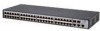
...Gigabit Ethernet short-wave (SX) and long-wave (LX) SFP transceivers in either half-duplex or full-duplex mode. 10 INTRODUCING THE BASELINE SWITCH 10/100 Mbps ports can only operate in full duplex mode. Physical Features Figures 1, 2, and 3 show the front and rear panels of the... Switch. This capability gives network administrators centralized power control for devices such as IP phones and wireless access points, which translates into greater network ...
...Gigabit Ethernet short-wave (SX) and long-wave (LX) SFP transceivers in either half-duplex or full-duplex mode. 10 INTRODUCING THE BASELINE SWITCH 10/100 Mbps ports can only operate in full duplex mode. Physical Features Figures 1, 2, and 3 show the front and rear panels of the... Switch. This capability gives network administrators centralized power control for devices such as IP phones and wireless access points, which translates into greater network ...
User Guide
Page 11
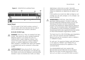
...;rfen an diese Datensteckdosen angeschlossen werden. Ceux-ci sont protégés par des prises de données. Figure 3 3CBLSF50 Front and Rear Panels Front Panel The front panel of the Switch contains a series of indicator lights (LEDs) that help describe the state of the connected device. Only connect RJ-45...
...;rfen an diese Datensteckdosen angeschlossen werden. Ceux-ci sont protégés par des prises de données. Figure 3 3CBLSF50 Front and Rear Panels Front Panel The front panel of the Switch contains a series of indicator lights (LEDs) that help describe the state of the connected device. Only connect RJ-45...
User Guide
Page 12
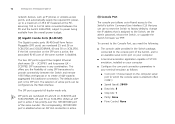
.... The SFP port supports full duplex mode only. When an SFP port is the SFP port. 12 INTRODUCING THE BASELINE SWITCH network devices, such as follows: ■ Com port: Choose based on 3CBLSF50. The default active port is active it has priority over the 10/100/1000 port of -band access to the... Switch's built-in any combination. This offers you can be configured via TFTP. The corresponding 10/100/1000 port is ...
.... The SFP port supports full duplex mode only. When an SFP port is the SFP port. 12 INTRODUCING THE BASELINE SWITCH network devices, such as follows: ■ Com port: Choose based on 3CBLSF50. The default active port is active it has priority over the 10/100/1000 port of -band access to the... Switch's built-in any combination. This offers you can be configured via TFTP. The corresponding 10/100/1000 port is ...

User Guide
Page 13
...TX Link/Activity Status LEDs Status Meaning Green The link is operating at 100 Mbps. (4) 10/100BASE-TX Link/Activity Status LEDs The top row (3CBLSF50) and the first (top) and third rows (3CBLSF26/3CBLSF26PWR) of LEDs, which are colored yellow, show the link, activity and speed status of...The link has not been established, nothing is connected to the port, or there is faulty. Flashing Packets are being received or transmitted on 3CBLSF50 (and 3CBLSF26/3CBLSF26PWR) can also be that the attached device is powered on the Green port at 100 Mbps. Off The link is operating ...
...TX Link/Activity Status LEDs Status Meaning Green The link is operating at 100 Mbps. (4) 10/100BASE-TX Link/Activity Status LEDs The top row (3CBLSF50) and the first (top) and third rows (3CBLSF26/3CBLSF26PWR) of LEDs, which are colored yellow, show the link, activity and speed status of...The link has not been established, nothing is connected to the port, or there is faulty. Flashing Packets are being received or transmitted on 3CBLSF50 (and 3CBLSF26/3CBLSF26PWR) can also be that the attached device is powered on the Green port at 100 Mbps. Off The link is operating ...

User Guide
Page 14
... the port, or there is a problem: ■ Check that the attached device is powered on the port at 10 or 100 Mbps. 14 INTRODUCING THE BASELINE SWITCH 1000BASE-T Mode Table 3 1000BASE-T Link/Activity Status LEDs Link/Activity Meaning Green The link is operating at 1000 Mbps. If these checks do not identify...
... the port, or there is a problem: ■ Check that the attached device is powered on the port at 10 or 100 Mbps. 14 INTRODUCING THE BASELINE SWITCH 1000BASE-T Mode Table 3 1000BASE-T Link/Activity Status LEDs Link/Activity Meaning Green The link is operating at 1000 Mbps. If these checks do not identify...

User Guide
Page 15
...intend to each marked corner area on the module. (7) Power LED The Power LED shows the power status of the Switch contains the power supply socket. (9) Power Socket The Switch automatically adjusts to the supply voltage. Only use . The SFP module will only disable the 1000BASE-T interface once there ...is supplied with four self-adhesive rubber pads. Rear Panel The rear panel of the Switch. Off The unit is not receiving power. ■ Check that is a valid link on the underside of the lower unit. If the ...
...intend to each marked corner area on the module. (7) Power LED The Power LED shows the power status of the Switch contains the power supply socket. (9) Power Socket The Switch automatically adjusts to the supply voltage. Only use . The SFP module will only disable the 1000BASE-T interface once there ...is supplied with four self-adhesive rubber pads. Rear Panel The rear panel of the Switch. Off The unit is not receiving power. ■ Check that is a valid link on the underside of the lower unit. If the ...
User Guide
Page 16
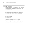
If any of the above items are damaged or missing, contact your Switch package is powered from the AC supply. The Switch comes with: ■ One power cord ■ One console cable ■ Four standard height, self-adhesive rubber pads ■ One mounting kit (part number 123193-104) ■ Installation CD ■ This User Guide ■ Warranty flyer The Switch is complete. 16 INTRODUCING THE BASELINE SWITCH Package Contents Before installing and using the Switch, verify that your 3Com network supplier immediately.
If any of the above items are damaged or missing, contact your Switch package is powered from the AC supply. The Switch comes with: ■ One power cord ■ One console cable ■ Four standard height, self-adhesive rubber pads ■ One mounting kit (part number 123193-104) ■ Installation CD ■ This User Guide ■ Warranty flyer The Switch is complete. 16 INTRODUCING THE BASELINE SWITCH Package Contents Before installing and using the Switch, verify that your 3Com network supplier immediately.
User Guide
Page 17
...aussi le télécharger sur le site Web de 3Com à: www.3Com.com Wichtige Sicherheits Informationen Bitte wenden Sie sich an die Sicherheitsinformationen in the 3Com Switch Family Safety and Regulatory Information manual included with your switch. It covers the following topics: ■ Important Safety ...Please refer to install and set up the Switch. You can find the 3Com Switch Family Safety and Regulatory Information manual on the product CD-ROM that you need to the safety information found in der 3Com Switch Family Safety and Regulatory Information Anleitung die mit...
...aussi le télécharger sur le site Web de 3Com à: www.3Com.com Wichtige Sicherheits Informationen Bitte wenden Sie sich an die Sicherheitsinformationen in the 3Com Switch Family Safety and Regulatory Information manual included with your switch. It covers the following topics: ■ Important Safety ...Please refer to install and set up the Switch. You can find the 3Com Switch Family Safety and Regulatory Information manual on the product CD-ROM that you need to the safety information found in der 3Com Switch Family Safety and Regulatory Information Anleitung die mit...
User Guide
Page 18
... and air conditioning units. Importante Avviso di Sicurezza Vi preghiamo di leggere attentamente e seguire le istruzioni indicate nel manuale di sicurezza "3Com Switch Family Safety and Regulatory Information", che troverete incluso a questo prodotto. bezpieczeństwa Informacje dotyczące bezpieczeństwa są...; umieszczone w Instrukcji obsługi 3Com Switch Family, która jest do łączona do tego produktu. Istnieje także możliwość ...
... and air conditioning units. Importante Avviso di Sicurezza Vi preghiamo di leggere attentamente e seguire le istruzioni indicate nel manuale di sicurezza "3Com Switch Family Safety and Regulatory Information", che troverete incluso a questo prodotto. bezpieczeństwa Informacje dotyczące bezpieczeństwa są...; umieszczone w Instrukcji obsługi 3Com Switch Family, która jest do łączona do tego produktu. Istnieje także możliwość ...
User Guide
Page 19
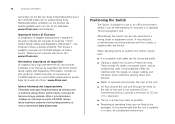
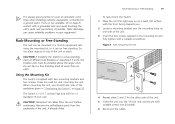
If one side of different size Baseline or Superstack 3 units, the smaller units must be free standing. Rack-Mounting or Free-Standing The unit can be mounted in "Positioning the Switch" on page 18. Do not have a free-standing stack of the unit. 5 Insert the unit into the 19-inch rack and secure... (1.7 inches) high and will fit in the mounting kit and fully tighten with a suitable screwdriver. Rack-Mounting or Free-Standing 19 To rack-mount the Switch: 1 Place the unit the right way up on a hard, flat surface with the front facing towards you should take note of the guidelines given in...
If one side of different size Baseline or Superstack 3 units, the smaller units must be free standing. Rack-Mounting or Free-Standing The unit can be mounted in "Positioning the Switch" on page 18. Do not have a free-standing stack of the unit. 5 Insert the unit into the 19-inch rack and secure... (1.7 inches) high and will fit in the mounting kit and fully tighten with a suitable screwdriver. Rack-Mounting or Free-Standing 19 To rack-mount the Switch: 1 Place the unit the right way up on a hard, flat surface with the front facing towards you should take note of the guidelines given in...

User Guide
Page 21
.... This is powered on and ready to reconfigure the Switch after POST. The following : ■ Power off the Switch is connected correctly, and then try powering on the Switch again ■ If the Switch still does not operate, contact your 3Com network supplier for more information. 2 Plug the other ... Checking for more information. You will need to use. If these do not resolve the issue: ■ Check the 3Com Knowledgebase for the Power LED after you power on the Switch, it means that the power cord is by connecting and disconnecting the power cord. When the...
.... This is powered on and ready to reconfigure the Switch after POST. The following : ■ Power off the Switch is connected correctly, and then try powering on the Switch again ■ If the Switch still does not operate, contact your 3Com network supplier for more information. 2 Plug the other ... Checking for more information. You will need to use. If these do not resolve the issue: ■ Check the 3Com Knowledgebase for the Power LED after you power on the Switch, it means that the power cord is by connecting and disconnecting the power cord. When the...

User Guide
Page 22
...faulty, it will not recognize it. See "Troubleshooting" on the 3Com Web site, enter this transceiver to connect the Switch directly to a single mode fiber-optic cable or to multimode fiber using 3Com SFPs in the Switch. SFP transceivers are hot-insertable and hot-swappable. If you ...1000BASE-LX SFP transceiver Use this URL into your Internet browser: http://www.3Com.com 3Com recommends using a conditioned launch cable. Ensure the wire release lever is closed (in Figure 5. 22 INSTALLING THE SWITCH Using SFP Tranceivers The following list of approved SFP transceivers is correct at the...
...faulty, it will not recognize it. See "Troubleshooting" on the 3Com Web site, enter this transceiver to connect the Switch directly to a single mode fiber-optic cable or to multimode fiber using 3Com SFPs in the Switch. SFP transceivers are hot-insertable and hot-swappable. If you ...1000BASE-LX SFP transceiver Use this URL into your Internet browser: http://www.3Com.com 3Com recommends using a conditioned launch cable. Ensure the wire release lever is closed (in Figure 5. 22 INSTALLING THE SWITCH Using SFP Tranceivers The following list of approved SFP transceivers is correct at the...