
Getting Started Guide
Page 1
DUA1730-0AAA02 Published October 2002 SuperStack® 3 Switch 4200 Series Getting Started Guide 3C17300 3C17302 3C17304 http://www.3com.com/ Part No.
DUA1730-0AAA02 Published October 2002 SuperStack® 3 Switch 4200 Series Getting Started Guide 3C17300 3C17302 3C17304 http://www.3com.com/ Part No.
Getting Started Guide
Page 3
...Online Documentation 10 Product Registration 10 Documentation Comments 10 1 INTRODUCING THE SUPERSTACK 3 SWITCH 4200 SERIES About the Switch 4200 Series 12 Summary of Each Other 23 Stacking Units 23 The Power-up Sequence 24 Powering-up the Switch 4200 Series 24 Rear View Detail 17 Power Socket 17 Redundant ...Power System Socket 17 Console Port 17 Default Settings 18 2 INSTALLING THE SWITCH Package Contents 20 Choosing a Suitable Site 20 Rack-mounting 21 Placing Units On Top of Hardware Features 12 Switch 4200 Series - Front View Detail 13 10BASE-T/ 100BASE-TX Ports 14 10/100...
...Online Documentation 10 Product Registration 10 Documentation Comments 10 1 INTRODUCING THE SUPERSTACK 3 SWITCH 4200 SERIES About the Switch 4200 Series 12 Summary of Each Other 23 Stacking Units 23 The Power-up Sequence 24 Powering-up the Switch 4200 Series 24 Rear View Detail 17 Power Socket 17 Redundant ...Power System Socket 17 Console Port 17 Default Settings 18 2 INSTALLING THE SWITCH Package Contents 20 Choosing a Suitable Site 20 Rack-mounting 21 Placing Units On Top of Hardware Features 12 Switch 4200 Series - Front View Detail 13 10BASE-T/ 100BASE-TX Ports 14 10/100...
Getting Started Guide
Page 4
... Connecting to a Front Panel Port 35 Connecting to the Console Port 38 Viewing Automatically Configured IP Information 42 Using 3Com Network Supervisor 42 Connecting to the Console Port 42 Methods of Managing a Switch 45 Command Line Interface Management 45 Web Interface Management 46 SNMP Management 46 Setting Up Command Line Interface Management...
... Connecting to a Front Panel Port 35 Connecting to the Console Port 38 Viewing Automatically Configured IP Information 42 Using 3Com Network Supervisor 42 Connecting to the Console Port 42 Methods of Managing a Switch 45 Command Line Interface Management 45 Web Interface Management 46 SNMP Management 46 Setting Up Command Line Interface Management...

Getting Started Guide
Page 5
... Modem Cable 68 RJ-45 Pin Assignments 68 1000BASE-T RJ-45 Pin Assignments 69 C TECHNICAL SPECIFICATIONS Switch 4226T (3C17300) 71 Switch 4250T (3C17302) 73 Switch 4228G (3C17304) 74 D TECHNICAL SUPPORT Online Technical Services 75 World Wide Web Site 75 3Com Knowledgebase Web Services 76 3Com FTP Site 76 Support from Your Network Supplier 76 Support from...
... Modem Cable 68 RJ-45 Pin Assignments 68 1000BASE-T RJ-45 Pin Assignments 69 C TECHNICAL SPECIFICATIONS Switch 4226T (3C17300) 71 Switch 4250T (3C17302) 73 Switch 4228G (3C17304) 74 D TECHNICAL SUPPORT Online Technical Services 75 World Wide Web Site 75 3Com Knowledgebase Web Services 76 3Com FTP Site 76 Support from Your Network Supplier 76 Support from...

Getting Started Guide
Page 7
... install and use a SuperStack® 3 Switch 4200 in Adobe Acrobat Reader Portable Document Format (PDF) or HTML on the 3Com World Wide Web site: http://www.3com.com/ If the information in the release notes that are shipped with all Switch 4200 Series models: ■ Switch 4226T (3C17300) - 24 ...10BASE-T/100BASE-TX ports, 2 10/100/1000BASE-T ports ■ Switch 4250T (3C17302) - 48 10BASE-T/...
... install and use a SuperStack® 3 Switch 4200 in Adobe Acrobat Reader Portable Document Format (PDF) or HTML on the 3Com World Wide Web site: http://www.3com.com/ If the information in the release notes that are shipped with all Switch 4200 Series models: ■ Switch 4226T (3C17300) - 24 ...10BASE-T/100BASE-TX ports, 2 10/100/1000BASE-T ports ■ Switch 4250T (3C17302) - 48 10BASE-T/...
Getting Started Guide
Page 9
... Documentation accompanying 3Com Network Supervisor. Related Documentation 9 Related Documentation In addition to this guide, each Switch documentation set includes the following: ■ SuperStack 3 Switch Implementation Guide This guide contains information on the CD-ROM that accompanies the Switch. ■ SuperStack 3 Switch Management Quick ...: ■ a list of the web interface and command line interface commands for the Switch. ■ SuperStack 3 Switch Management Interface Reference Guide This guide provides detailed information about the current software release, including ...
... Documentation accompanying 3Com Network Supervisor. Related Documentation 9 Related Documentation In addition to this guide, each Switch documentation set includes the following: ■ SuperStack 3 Switch Implementation Guide This guide contains information on the CD-ROM that accompanies the Switch. ■ SuperStack 3 Switch Management Quick ...: ■ a list of the web interface and command line interface commands for the Switch. ■ SuperStack 3 Switch Management Interface Reference Guide This guide provides detailed information about the current software release, including ...
Getting Started Guide
Page 10
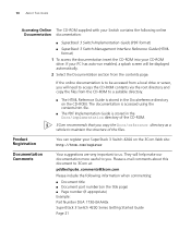
Please e-mail comments about this document to 3Com at: pddtechpubs_comments@3com.com Please include the following online Documentation documentation: ■ SuperStack 3 Switch Implementation Guide (PDF format) ■ SuperStack 3 Switch Management Interface Reference Guide (HTML format) 1 To access the documentation ... directory and copy the files from the contents page. Product Registration You can register your SuperStack 3 Switch 4200 on the 3Com Web site: http://3com.com/register Documentation Comments Your suggestions are very important to be displayed automatically. 2 Select...
Please e-mail comments about this document to 3Com at: pddtechpubs_comments@3com.com Please include the following online Documentation documentation: ■ SuperStack 3 Switch Implementation Guide (PDF format) ■ SuperStack 3 Switch Management Interface Reference Guide (HTML format) 1 To access the documentation ... directory and copy the files from the contents page. Product Registration You can register your SuperStack 3 Switch 4200 on the 3Com Web site: http://3com.com/register Documentation Comments Your suggestions are very important to be displayed automatically. 2 Select...

Getting Started Guide
Page 11
Front View Detail ■ Switch 4200 Series - Rear View Detail ■ Default Settings It covers summaries of hardware and software features and also the following topics: ■ About the Switch 4200 Series ■ Switch 4200 Series - 1 INTRODUCING THE SUPERSTACK 3 SWITCH 4200 SERIES This chapter contains introductory information about the Switch 4200 Series and how it can be used in your network.
Front View Detail ■ Switch 4200 Series - Rear View Detail ■ Default Settings It covers summaries of hardware and software features and also the following topics: ■ About the Switch 4200 Series ■ Switch 4200 Series - 1 INTRODUCING THE SUPERSTACK 3 SWITCH 4200 SERIES This chapter contains introductory information about the Switch 4200 Series and how it can be used in your network.
Getting Started Guide
Page 12
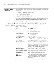
... the hardware features that are supported by the Switch 4200 Series. Table 3 Hardware features Feature Switch 4200 Series Addresses ■ Up to 8000 supported ■ Up to any SuperStack® system as your network grows. 12 CHAPTER 1: INTRODUCING THE SUPERSTACK 3 SWITCH 4200 SERIES About the Switch 4200 Series The Switch 4200 Series are stackable 10/100/1000...
... the hardware features that are supported by the Switch 4200 Series. Table 3 Hardware features Feature Switch 4200 Series Addresses ■ Up to 8000 supported ■ Up to any SuperStack® system as your network grows. 12 CHAPTER 1: INTRODUCING THE SUPERSTACK 3 SWITCH 4200 SERIES About the Switch 4200 Series The Switch 4200 Series are stackable 10/100/1000...
Getting Started Guide
Page 13
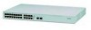
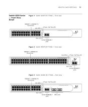
... 22 11 23 12 24 Power/ Self Test 1 25 / Up 26 / Down 2 3 Alert 4 Unit Alert LED 10/100/1000BASE-T ports 3C17300 Superstack 3 Switch 4226T Figure 2 Switch 4250T (3C17302) - About the Switch 4200 Series 13 Switch 4200 Series - front view 10BASE-T / 100BASE-TX RJ-45 Ports Unit LEDs Power / Self Test LED 1 25 2 26 3 27 4 28 5 29... 6 30 7 31 8 32 9 33 10 34 11 35 12 36 13 37 14 38 15 39 16 40 17 41 18 42 19 43 3C17302 Superstack 3 Switch 4250T 20 44 21 45 22 46 23 47 24 48 Power/ Self Test 1 Up Down 2 3 Alert 4 Unit 49 50 Alert LED 10/100/1000BASE...
... 22 11 23 12 24 Power/ Self Test 1 25 / Up 26 / Down 2 3 Alert 4 Unit Alert LED 10/100/1000BASE-T ports 3C17300 Superstack 3 Switch 4226T Figure 2 Switch 4250T (3C17302) - About the Switch 4200 Series 13 Switch 4200 Series - front view 10BASE-T / 100BASE-TX RJ-45 Ports Unit LEDs Power / Self Test LED 1 25 2 26 3 27 4 28 5 29... 6 30 7 31 8 32 9 33 10 34 11 35 12 36 13 37 14 38 15 39 16 40 17 41 18 42 19 43 3C17302 Superstack 3 Switch 4250T 20 44 21 45 22 46 23 47 24 48 Power/ Self Test 1 Up Down 2 3 Alert 4 Unit 49 50 Alert LED 10/100/1000BASE...
Getting Started Guide
Page 14
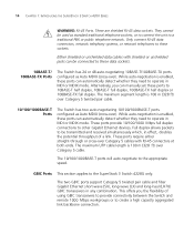
...Alternatively, you the flexibility of a link. While auto-negotiation is enabled, these sockets. These ports provide 10/100/1000 Mbps full duplex connections to the SuperStack 3 Switch 4228G only. The maximum UTP cable length is 100 m (328 ft) over Category 5 cable. The maximum segment length is 100 m (328 ft...MDIX (cross-over ). Either shielded or unshielded data cables with RJ-45 connectors at both ends. 14 CHAPTER 1: INTRODUCING THE SUPERSTACK 3 SWITCH 4200 SERIES WARNING: RJ-45 Ports. They cannot be connected to create a high capacity aggregated link backbone connection.
...Alternatively, you the flexibility of a link. While auto-negotiation is enabled, these sockets. These ports provide 10/100/1000 Mbps full duplex connections to the SuperStack 3 Switch 4228G only. The maximum UTP cable length is 100 m (328 ft) over Category 5 cable. The maximum segment length is 100 m (328 ft...MDIX (cross-over ). Either shielded or unshielded data cables with RJ-45 connectors at both ends. 14 CHAPTER 1: INTRODUCING THE SUPERSTACK 3 SWITCH 4200 SERIES WARNING: RJ-45 Ports. They cannot be connected to create a high capacity aggregated link backbone connection.

Getting Started Guide
Page 15
... for flow control support, effectively enabling or disabling flow control. Green flashing Packets are being transmitted/received on page 54. About the Switch 4200 Series 15 Fiber GBIC's. Yellow A 10 Mbps link is present and the port is present. alternating Off No link is enabled.... Although it is not possible to disable auto-negotiation it is possible to the "SuperStack 3 Switch Management Interface Reference Guide" on the front of the Switch, and how to read their status according to 1000BASE-T, full duplex only. Table 4 LED behavior LED Color...
... for flow control support, effectively enabling or disabling flow control. Green flashing Packets are being transmitted/received on page 54. About the Switch 4200 Series 15 Fiber GBIC's. Yellow A 10 Mbps link is present and the port is present. alternating Off No link is enabled.... Although it is not possible to disable auto-negotiation it is possible to the "SuperStack 3 Switch Management Interface Reference Guide" on the front of the Switch, and how to read their status according to 1000BASE-T, full duplex only. Table 4 LED behavior LED Color...

Getting Started Guide
Page 16
...Power Supply Unit. Off The Switch Alert LED has been configured via the CLI or Web Interface to Chapter 4 Solving Problems Indicated by LEDs. Green / Yellow A 10, 100 or 1000 Mbps link present but disabled. 16 CHAPTER 1: INTRODUCING THE SUPERSTACK 3 SWITCH 4200 SERIES LED Color Indicates ...Green flashing Packets are being transmitted/received on the port. Yellow The Switch has failed its Power On Self Test.
...Power Supply Unit. Off The Switch Alert LED has been configured via the CLI or Web Interface to Chapter 4 Solving Problems Indicated by LEDs. Green / Yellow A 10, 100 or 1000 Mbps link present but disabled. 16 CHAPTER 1: INTRODUCING THE SUPERSTACK 3 SWITCH 4200 SERIES LED Color Indicates ...Green flashing Packets are being transmitted/received on the port. Yellow The Switch has failed its Power On Self Test.
Getting Started Guide
Page 17
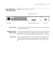
...Redundant Power System" on page 25. rear view - Console Port The console port allows you can use this socket System Socket to connect a Switch 4200 to connect a terminal and perform remote or local out-of-band management. The console port uses a standard null modem cable and is ...set to any supply voltage in the range 90-240 VAC. About the Switch 4200 Series 17 Switch 4200 Series Figure 4 Switch 4200 Series - Redundant Power To protect against internal power supply failure, you to a SuperStack Advanced Redundant Power System (RPS).
...Redundant Power System" on page 25. rear view - Console Port The console port allows you can use this socket System Socket to connect a Switch 4200 to connect a terminal and perform remote or local out-of-band management. The console port uses a standard null modem cable and is ...set to any supply voltage in the range 90-240 VAC. About the Switch 4200 Series 17 Switch 4200 Series Figure 4 Switch 4200 Series - Redundant Power To protect against internal power supply failure, you to a SuperStack Advanced Redundant Power System (RPS).

Getting Started Guide
Page 18
...QoS) All ports prioritize NBX VoIP IP. 18 CHAPTER 1: INTRODUCING THE SUPERSTACK 3 SWITCH 4200 SERIES Default Settings Table 5 shows the default settings for the Switch 4200 Series: Table 5 Default Settings Feature Switch 4200 Series Automatic IP Configuration Enabled Port Status Enabled Port Speed All ports...in half duplex ■ Auto-negotiated in the Command Line Interface, the following settings are retained to allow you initialize a Switch unit by selecting System > Control > Initialize in the Web interface or by entering system control initialize in full duplex Broadcast ...
...QoS) All ports prioritize NBX VoIP IP. 18 CHAPTER 1: INTRODUCING THE SUPERSTACK 3 SWITCH 4200 SERIES Default Settings Table 5 shows the default settings for the Switch 4200 Series: Table 5 Default Settings Feature Switch 4200 Series Automatic IP Configuration Enabled Port Status Enabled Port Speed All ports...in half duplex ■ Auto-negotiated in the Command Line Interface, the following settings are retained to allow you initialize a Switch unit by selecting System > Control > Initialize in the Web interface or by entering system control initialize in full duplex Broadcast ...
Getting Started Guide
Page 19
...é qui se trouvent dans l'Appendice A de ce guide. VORSICHT: Sicherheitsinformationen. Before installing or removing any components from the Switch 4200 Series or carrying out any maintenance procedures, you need to install and set up Sequence ■ GBIC Operation WARNING: Safety... Information. Bevor Sie Komponenten aus dem Switch 4200 entfernen oder dem Switch 4200 hinzufuegen oder Instandhaltungsarbeiten verrichten, lesen Sie die Sicherheitsanweisungen, die in Appendix A (Anhang A) in Appendix A of Each...
...é qui se trouvent dans l'Appendice A de ce guide. VORSICHT: Sicherheitsinformationen. Before installing or removing any components from the Switch 4200 Series or carrying out any maintenance procedures, you need to install and set up Sequence ■ GBIC Operation WARNING: Safety... Information. Bevor Sie Komponenten aus dem Switch 4200 entfernen oder dem Switch 4200 hinzufuegen oder Instandhaltungsarbeiten verrichten, lesen Sie die Sicherheitsanweisungen, die in Appendix A (Anhang A) in Appendix A of Each...
Getting Started Guide
Page 20
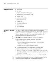
...standard 19-inch equipment rack. CAUTION: Ensure that you provide a minimum of 25mm (1in.) clearance. ■ Air temperature around the Switch or through the vents in a wiring closet or equipment room, as radios, transmitters and broadband amplifiers. ■ power lines and ... ■ Power Cord ■ 2 x Mounting brackets ■ 4 x Screws ■ 4 x Rubber feet Choosing a Suitable Site The Switch is suited for other Hubs and Switches. Alternatively, the Switch can be mounted in the side of the Switch. 3Com recommends that the ventilation holes are not obstructed. If the...
...standard 19-inch equipment rack. CAUTION: Ensure that you provide a minimum of 25mm (1in.) clearance. ■ Air temperature around the Switch or through the vents in a wiring closet or equipment room, as radios, transmitters and broadband amplifiers. ■ power lines and ... ■ Power Cord ■ 2 x Mounting brackets ■ 4 x Screws ■ 4 x Rubber feet Choosing a Suitable Site The Switch is suited for other Hubs and Switches. Alternatively, the Switch can be mounted in the side of the Switch. 3Com recommends that the ventilation holes are not obstructed. If the...
Getting Started Guide
Page 21
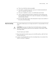
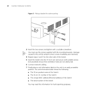
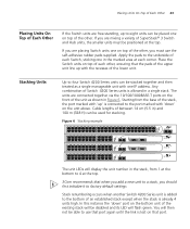
... bracket over the mounting holes on top of one side of the Switch, as possible. ■ The switch is separate to that used by the switch is situated away from the underside of the Switch if they have been fitted. Rack-mounting The Switch 4200 Series are free-standing. Rack-mounting 21 ■ The air... AC supply used by units that generate high levels of AC noise, for example, air-conditioning units and laser printers. ■ No more than eight Switch units are placed on one another, if the units are 1U high and will fit in Figure 5.
... bracket over the mounting holes on top of one side of the Switch, as possible. ■ The switch is separate to that used by the switch is situated away from the underside of the Switch if they have been fitted. Rack-mounting The Switch 4200 Series are free-standing. Rack-mounting 21 ■ The air... AC supply used by units that generate high levels of AC noise, for example, air-conditioning units and laser printers. ■ No more than eight Switch units are placed on one another, if the units are 1U high and will fit in Figure 5.
Getting Started Guide
Page 22
...The unit information label shows the following: ■ The 3Com product name of the Switch ■ The 3Com 3C number of the Switch ■ The unique MAC address (Ethernet address) of the Switch ■ The serial number of the Switch. 5 Insert the Switch into the 19-inch rack and secure with a suitable ... caused to the unit by using incorrect screws invalidates your warranty. 4 Repeat steps 2 and 3 for the other side of the Switch You may need this information for rack-mounting 3 Insert the two screws and tighten with suitable screws (not provided). 22 CHAPTER 2: INSTALLING THE...
...The unit information label shows the following: ■ The 3Com product name of the Switch ■ The 3Com 3C number of the Switch ■ The unique MAC address (Ethernet address) of the Switch ■ The serial number of the Switch. 5 Insert the Switch into the 19-inch rack and secure with a suitable ... caused to the unit by using incorrect screws invalidates your warranty. 4 Repeat steps 2 and 3 for the other side of the Switch You may need this information for rack-mounting 3 Insert the two screws and tighten with suitable screws (not provided). 22 CHAPTER 2: INSTALLING THE...
Getting Started Guide
Page 23
... 1 13 2 14 3 15 4 16 5 17 6 18 7 19 8 20 9 21 10 22 11 23 12 24 Power/ Self Test 1 25 / Up 26 / Down 2 3 Alert 4 Unit 3C17300 Superstack 3 Switch 4226T The unit LEDs will flash green. Cable lengths of between 14 cm (5.5 in) and 100 m (328 ft) can be stacked together and then treated as... 'down ' on the front of the unit as a single manageable unit with one on top of the other , you must be positioned at the top. 3Com recommends that when you add a new unit to a stack, you should first initialize it to factory default settings Stack renumbering occurs when another...
... 1 13 2 14 3 15 4 16 5 17 6 18 7 19 8 20 9 21 10 22 11 23 12 24 Power/ Self Test 1 25 / Up 26 / Down 2 3 Alert 4 Unit 3C17300 Superstack 3 Switch 4226T The unit LEDs will flash green. Cable lengths of between 14 cm (5.5 in) and 100 m (328 ft) can be stacked together and then treated as... 'down ' on the front of the unit as a single manageable unit with one on top of the other , you must be positioned at the top. 3Com recommends that when you add a new unit to a stack, you should first initialize it to factory default settings Stack renumbering occurs when another...


