
Getting Started Guide
Page 1
SuperStack® 3 Switch 4200 Series Getting Started Guide 3C17300 3C17302 3C17304 http://www.3com.com/ Part No. DUA1730-0AAA02 Published October 2002
SuperStack® 3 Switch 4200 Series Getting Started Guide 3C17300 3C17302 3C17304 http://www.3com.com/ Part No. DUA1730-0AAA02 Published October 2002
Getting Started Guide
Page 3
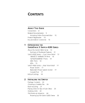
... Ports 14 10/100/1000BASE-T Ports 14 GBIC Ports 14 LEDs 15 Switch 4200 Series - CONTENTS ABOUT THIS GUIDE Conventions 8 Related Documentation 9 Accessing Online Documentation 10 Product Registration 10 Documentation Comments 10 1 INTRODUCING THE SUPERSTACK 3 SWITCH 4200 SERIES About the Switch 4200 Series 12 Summary of Each Other 23 Stacking Units 23 The Power...
... Ports 14 10/100/1000BASE-T Ports 14 GBIC Ports 14 LEDs 15 Switch 4200 Series - CONTENTS ABOUT THIS GUIDE Conventions 8 Related Documentation 9 Accessing Online Documentation 10 Product Registration 10 Documentation Comments 10 1 INTRODUCING THE SUPERSTACK 3 SWITCH 4200 SERIES About the Switch 4200 Series 12 Summary of Each Other 23 Stacking Units 23 The Power...
Getting Started Guide
Page 4
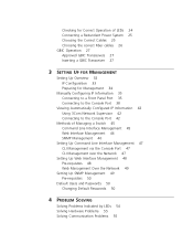
... Connecting to a Front Panel Port 35 Connecting to the Console Port 38 Viewing Automatically Configured IP Information 42 Using 3Com Network Supervisor 42 Connecting to the Console Port 42 Methods of Managing a Switch 45 Command Line Interface Management 45 Web Interface Management 46 SNMP Management 46 Setting Up Command Line Interface Management...
... Connecting to a Front Panel Port 35 Connecting to the Console Port 38 Viewing Automatically Configured IP Information 42 Using 3Com Network Supervisor 42 Connecting to the Console Port 42 Methods of Managing a Switch 45 Command Line Interface Management 45 Web Interface Management 46 SNMP Management 46 Setting Up Command Line Interface Management...

Getting Started Guide
Page 5
... Modem Cable 68 RJ-45 Pin Assignments 68 1000BASE-T RJ-45 Pin Assignments 69 C TECHNICAL SPECIFICATIONS Switch 4226T (3C17300) 71 Switch 4250T (3C17302) 73 Switch 4228G (3C17304) 74 D TECHNICAL SUPPORT Online Technical Services 75 World Wide Web Site 75 3Com Knowledgebase Web Services 76 3Com FTP Site 76 Support from Your Network Supplier 76 Support from...
... Modem Cable 68 RJ-45 Pin Assignments 68 1000BASE-T RJ-45 Pin Assignments 69 C TECHNICAL SPECIFICATIONS Switch 4226T (3C17300) 71 Switch 4250T (3C17302) 73 Switch 4228G (3C17304) 74 D TECHNICAL SUPPORT Online Technical Services 75 World Wide Web Site 75 3Com Knowledgebase Web Services 76 3Com FTP Site 76 Support from Your Network Supplier 76 Support from...

Getting Started Guide
Page 7
... (PDF) or HTML on the 3Com World Wide Web site: http://www.3com.com/ Most user guides and release notes are shipped with all models except where stated. ABOUT THIS GUIDE This guide provides all the information you need to all Switch 4200 Series models: ■ Switch 4226T (3C17300) - 24 10BASE-T/100BASE-...by network administrators who are responsible for use with your product differ from the information in this guide apply to install and use a SuperStack® 3 Switch 4200 in its default state. consequently, it assumes a basic working knowledge of LANs (Local Area Networks).
... (PDF) or HTML on the 3Com World Wide Web site: http://www.3com.com/ Most user guides and release notes are shipped with all models except where stated. ABOUT THIS GUIDE This guide provides all the information you need to all Switch 4200 Series models: ■ Switch 4226T (3C17300) - 24 10BASE-T/100BASE-...by network administrators who are responsible for use with your product differ from the information in this guide apply to install and use a SuperStack® 3 Switch 4200 in its default state. consequently, it assumes a basic working knowledge of LANs (Local Area Networks).
Getting Started Guide
Page 9
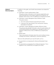
...3Com Network Supervisor. This is supplied in PDF format on the features supported by the Switch. ■ a summary of the software features supported by your Switch and how they can be used to optimize your network. Related Documentation 9 Related Documentation In addition to this guide, each Switch documentation set includes the following: ■ SuperStack 3 Switch... Implementation Guide This guide contains information on the CD-ROM that accompanies the Switch. ■ SuperStack 3 Switch Management ...
...3Com Network Supervisor. This is supplied in PDF format on the features supported by the Switch. ■ a summary of the software features supported by your Switch and how they can be used to optimize your network. Related Documentation 9 Related Documentation In addition to this guide, each Switch documentation set includes the following: ■ SuperStack 3 Switch... Implementation Guide This guide contains information on the CD-ROM that accompanies the Switch. ■ SuperStack 3 Switch Management ...
Getting Started Guide
Page 10
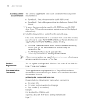
... your SuperStack 3 Switch 4200 on the 3Com Web site: http://3com.com/register Documentation Comments Your suggestions are very important to 3Com at: pddtechpubs_comments@3com.com Please include the following online Documentation documentation: ■ SuperStack 3 Switch Implementation Guide (PDF format) ■ SuperStack 3 Switch Management Interface...directory on the title page) ■ Page number (if appropriate) Example: Part Number DUA 1730-0AAA0x SuperStack 3 Switch 4200 Series Getting Started Guide Page 21 The documentation is accessed using the contents.htm file. ■...
... your SuperStack 3 Switch 4200 on the 3Com Web site: http://3com.com/register Documentation Comments Your suggestions are very important to 3Com at: pddtechpubs_comments@3com.com Please include the following online Documentation documentation: ■ SuperStack 3 Switch Implementation Guide (PDF format) ■ SuperStack 3 Switch Management Interface...directory on the title page) ■ Page number (if appropriate) Example: Part Number DUA 1730-0AAA0x SuperStack 3 Switch 4200 Series Getting Started Guide Page 21 The documentation is accessed using the contents.htm file. ■...

Getting Started Guide
Page 11
It covers summaries of hardware and software features and also the following topics: ■ About the Switch 4200 Series ■ Switch 4200 Series - 1 INTRODUCING THE SUPERSTACK 3 SWITCH 4200 SERIES This chapter contains introductory information about the Switch 4200 Series and how it can be used in your network. Rear View Detail ■ Default Settings Front View Detail ■ Switch 4200 Series -
It covers summaries of hardware and software features and also the following topics: ■ About the Switch 4200 Series ■ Switch 4200 Series - 1 INTRODUCING THE SUPERSTACK 3 SWITCH 4200 SERIES This chapter contains introductory information about the Switch 4200 Series and how it can be used in your network. Rear View Detail ■ Default Settings Front View Detail ■ Switch 4200 Series -
Getting Started Guide
Page 12
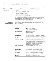
.... Table 3 Hardware features Feature Switch 4200 Series Addresses ■ Up to 8000 supported ■ Up to any SuperStack® system as your network grows. 12 CHAPTER 1: INTRODUCING THE SUPERSTACK 3 SWITCH 4200 SERIES About the Switch 4200 Series The Switch 4200 Series are stackable 10/100.../1000 Mbps devices which are supported by the Switch 4200 Series. Summary of : &#...
.... Table 3 Hardware features Feature Switch 4200 Series Addresses ■ Up to 8000 supported ■ Up to any SuperStack® system as your network grows. 12 CHAPTER 1: INTRODUCING THE SUPERSTACK 3 SWITCH 4200 SERIES About the Switch 4200 Series The Switch 4200 Series are stackable 10/100.../1000 Mbps devices which are supported by the Switch 4200 Series. Summary of : &#...
Getting Started Guide
Page 13
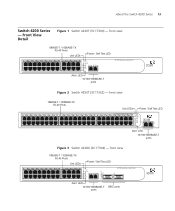
...12 36 13 37 14 38 15 39 16 40 17 41 18 42 19 43 3C17302 Superstack 3 Switch 4250T 20 44 21 45 22 46 23 47 24 48 Power/ Self Test 1 Up...Switch 4200 Series 13 Switch 4200 Series - front view 10BASE-T / 100BASE-TX RJ-45 Ports Unit LEDs Power / Self Test LED 1 13 2 14 3 15 4 16 5 17 6 18 7 19 8 20 9 21 10 22 11 23 12 24 Power/ Self Test 1 25 / Up 26 / Down 2 3 Alert 4 Unit Alert LED 10/100/1000BASE-T ports 3C17300 Superstack 3 Switch 4226T... Figure 2 Switch 4250T (3C17302) - Front View Detail Figure...
...12 36 13 37 14 38 15 39 16 40 17 41 18 42 19 43 3C17302 Superstack 3 Switch 4250T 20 44 21 45 22 46 23 47 24 48 Power/ Self Test 1 Up...Switch 4200 Series 13 Switch 4200 Series - front view 10BASE-T / 100BASE-TX RJ-45 Ports Unit LEDs Power / Self Test LED 1 13 2 14 3 15 4 16 5 17 6 18 7 19 8 20 9 21 10 22 11 23 12 24 Power/ Self Test 1 25 / Up 26 / Down 2 3 Alert 4 Unit Alert LED 10/100/1000BASE-T ports 3C17300 Superstack 3 Switch 4226T... Figure 2 Switch 4250T (3C17302) - Front View Detail Figure...
Getting Started Guide
Page 14
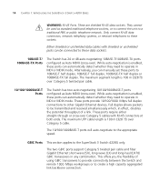
... you can automatically detect whether they need to operate in MDI or MDIX mode. Alternatively, you the flexibility of a link. 14 CHAPTER 1: INTRODUCING THE SUPERSTACK 3 SWITCH 4200 SERIES WARNING: RJ-45 Ports. The 10/100/1000BASE-T ports will auto-negotiate to other Gigabit Ethernet devices. Either shielded or unshielded data cables...SX), long-wave (LX) and long-haul (LH70) GBIC transceivers in effect, doubles the potential throughput of using GBIC transceivers to provide connectivity between the Switch and remote 1000 Mbps workgroups or to the SuperStack 3 Switch 4228G only.
... you can automatically detect whether they need to operate in MDI or MDIX mode. Alternatively, you the flexibility of a link. 14 CHAPTER 1: INTRODUCING THE SUPERSTACK 3 SWITCH 4200 SERIES WARNING: RJ-45 Ports. The 10/100/1000BASE-T ports will auto-negotiate to other Gigabit Ethernet devices. Either shielded or unshielded data cables...SX), long-wave (LX) and long-haul (LH70) GBIC transceivers in effect, doubles the potential throughput of using GBIC transceivers to provide connectivity between the Switch and remote 1000 Mbps workgroups or to the SuperStack 3 Switch 4228G only.

Getting Started Guide
Page 15
.... LEDs Table 4 lists LEDs visible on the CD-ROM that is enabled. For more detailed information, refer to the "SuperStack 3 Switch Management Interface Reference Guide" on the front of the Switch, and how to read their status according to 1000BASE-T, full duplex only. Table 4 LED behavior LED Color Indicates Port Status...-negotiation enabled, where speed, duplex and flow control modes are fixed by LEDs" on the port. For information on the port. About the Switch 4200 Series 15 Fiber GBIC's. Green / Yellow A 10 or 100 Mbps link is present, but the port is negotiated with the...
.... LEDs Table 4 lists LEDs visible on the CD-ROM that is enabled. For more detailed information, refer to the "SuperStack 3 Switch Management Interface Reference Guide" on the front of the Switch, and how to read their status according to 1000BASE-T, full duplex only. Table 4 LED behavior LED Color Indicates Port Status...-negotiation enabled, where speed, duplex and flow control modes are fixed by LEDs" on the port. For information on the port. About the Switch 4200 Series 15 Fiber GBIC's. Green / Yellow A 10 or 100 Mbps link is present, but the port is negotiated with the...

Getting Started Guide
Page 16
...Yellow A 10, 100 or 1000 Mbps link present but disabled. Refer to be off (Default state). Alert LED Green flashing The Switch Alert LED has been configured via the CLI or Web Interface to Chapter 4 Solving Problems Indicated by LEDs. alternating Off No link ...is not complete. Off The Switch initialization process is present. Yellow The Switch has failed its Power On Self Test. Unit LED number 1 can also indicate a stand-alone Switch. 16 CHAPTER 1: INTRODUCING THE SUPERSTACK 3 SWITCH 4200 SERIES LED Color Indicates Green flashing Packets are...
...Yellow A 10, 100 or 1000 Mbps link present but disabled. Refer to be off (Default state). Alert LED Green flashing The Switch Alert LED has been configured via the CLI or Web Interface to Chapter 4 Solving Problems Indicated by LEDs. alternating Off No link ...is not complete. Off The Switch initialization process is present. Yellow The Switch has failed its Power On Self Test. Unit LED number 1 can also indicate a stand-alone Switch. 16 CHAPTER 1: INTRODUCING THE SUPERSTACK 3 SWITCH 4200 SERIES LED Color Indicates Green flashing Packets are...
Getting Started Guide
Page 17
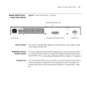
...bit. Rear View Detail Supply Data Warning Label Console (max) 19200,8,1,N Power Socket Redundant Power System Socket Console Port Power Socket The Switch automatically adjusts its power setting to connect a terminal and perform remote or local out-of-band management. The console port uses a ...standard null modem cable and is set to a SuperStack Advanced Redundant Power System (RPS). See "Connecting a Redundant Power System" on page 25. Redundant Power To protect against internal power supply ...
...bit. Rear View Detail Supply Data Warning Label Console (max) 19200,8,1,N Power Socket Redundant Power System Socket Console Port Power Socket The Switch automatically adjusts its power setting to connect a terminal and perform remote or local out-of-band management. The console port uses a ...standard null modem cable and is set to a SuperStack Advanced Redundant Power System (RPS). See "Connecting a Redundant Power System" on page 25. Redundant Power To protect against internal power supply ...

Getting Started Guide
Page 18
... Enabled Port Status Enabled Port Speed All ports are auto-negotiated Duplex Mode All ports are retained to allow you initialize a Switch unit by selecting System > Control > Initialize in the Web interface or by entering system control initialize in the Command Line Interface... Broadcast Storm Control Enabled Virtual LANs (VLANs) All ports belong to and manage the Switch: ■ IP Address ■ Subnet Mask ■ Default Router 18 CHAPTER 1: INTRODUCING THE SUPERSTACK 3 SWITCH 4200 SERIES Default Settings Table 5 shows the default settings for all ports RMON Alarm ...
... Enabled Port Status Enabled Port Speed All ports are auto-negotiated Duplex Mode All ports are retained to allow you initialize a Switch unit by selecting System > Control > Initialize in the Web interface or by entering system control initialize in the Command Line Interface... Broadcast Storm Control Enabled Virtual LANs (VLANs) All ports belong to and manage the Switch: ■ IP Address ■ Subnet Mask ■ Default Router 18 CHAPTER 1: INTRODUCING THE SUPERSTACK 3 SWITCH 4200 SERIES Default Settings Table 5 shows the default settings for all ports RMON Alarm ...
Getting Started Guide
Page 19
...you need to install and set up Sequence ■ GBIC Operation WARNING: Safety Information. Bevor Sie Komponenten aus dem Switch 4200 entfernen oder dem Switch 4200 hinzufuegen oder Instandhaltungsarbeiten verrichten, lesen Sie die Sicherheitsanweisungen, die in Appendix A (Anhang A) in Appendix A of Each...9632; Choosing a Suitable Site ■ Rack-mounting ■ Placing Units On Top of this guide. 2 INSTALLING THE SWITCH This chapter contains the information you must read the safety information provided in diesem Handbuch aufgefuehrt sind. Avant d'installer ou d'enlever tout ...
...you need to install and set up Sequence ■ GBIC Operation WARNING: Safety Information. Bevor Sie Komponenten aus dem Switch 4200 entfernen oder dem Switch 4200 hinzufuegen oder Instandhaltungsarbeiten verrichten, lesen Sie die Sicherheitsanweisungen, die in Appendix A (Anhang A) in Appendix A of Each...9632; Choosing a Suitable Site ■ Rack-mounting ■ Placing Units On Top of this guide. 2 INSTALLING THE SWITCH This chapter contains the information you must read the safety information provided in diesem Handbuch aufgefuehrt sind. Avant d'installer ou d'enlever tout ...
Getting Started Guide
Page 20
... or equipment room, as radios, transmitters and broadband amplifiers. ■ power lines and fluorescent lighting fixtures ■ The Switch is not restricted around the Switch or through the vents in the side of the Switch. 3Com recommends that you provide a minimum of electrical noise such as an aggregator for use on a desktop, either free...
... or equipment room, as radios, transmitters and broadband amplifiers. ■ power lines and fluorescent lighting fixtures ■ The Switch is not restricted around the Switch or through the vents in the side of the Switch. 3Com recommends that you provide a minimum of electrical noise such as an aggregator for use on a desktop, either free...
Getting Started Guide
Page 21
... air-conditioning units and laser printers. ■ No more than eight Switch units are 1U high and will fit in most standard 19-inch racks. Rack-mounting The Switch 4200 Series are placed on top of the Switch if they have been fitted. CAUTION: Disconnect all self adhesive pads from ...the underside of one side of the Switch, as possible. ■ The switch is situated away from sources of conductive (electrical) dust, for example, laser printers. ■ The unit is installed in a clean, air conditioned environment....
... air-conditioning units and laser printers. ■ No more than eight Switch units are 1U high and will fit in most standard 19-inch racks. Rack-mounting The Switch 4200 Series are placed on top of the Switch if they have been fitted. CAUTION: Disconnect all self adhesive pads from ...the underside of one side of the Switch, as possible. ■ The switch is situated away from sources of conductive (electrical) dust, for example, laser printers. ■ The unit is installed in a clean, air conditioned environment....
Getting Started Guide
Page 22
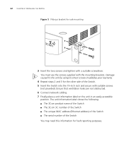
...The unit information label shows the following: ■ The 3Com product name of the Switch ■ The 3Com 3C number of the Switch ■ The unique MAC address (Ethernet address) of the Switch ■ The serial number of the Switch. 5 Insert the Switch into the 19-inch rack and secure with suitable screws ...). Damage caused to the unit by using incorrect screws invalidates your warranty. 4 Repeat steps 2 and 3 for the other side of the Switch You may need this information for rack-mounting 3 Insert the two screws and tighten with the mounting brackets. You must use the screws supplied...
...The unit information label shows the following: ■ The 3Com product name of the Switch ■ The 3Com 3C number of the Switch ■ The unique MAC address (Ethernet address) of the Switch ■ The serial number of the Switch. 5 Insert the Switch into the 19-inch rack and secure with suitable screws ...). Damage caused to the unit by using incorrect screws invalidates your warranty. 4 Repeat steps 2 and 3 for the other side of the Switch You may need this information for rack-mounting 3 Insert the two screws and tighten with the mounting brackets. You must use the screws supplied...
Getting Started Guide
Page 23
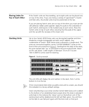
... 16 5 17 6 18 7 19 8 20 9 21 10 22 11 23 12 24 Power/ Self Test 1 25 / Up 26 / Down 2 3 Alert 4 Unit 27 27 28 3C17304 Superstack 3 Switch 4228G 28 1 13 2 14 3 15 4 16 5 17 6 18 7 19 8 20 9 21 10 22 11 23 12 24 Power/ Self Test 1 25 / Up 26 / Down.../ Up 26 / Down 2 3 Alert 4 Unit 3C17300 Superstack 3 Switch 4226T The unit LEDs will display the unit number in Figure 6. Place the Switch units on top of each corner. Starting from 1 at the bottom to 4 at the top. 3Com recommends that port. Any combination of Switch 4200 Series units is already 4 units high. You will...
... 16 5 17 6 18 7 19 8 20 9 21 10 22 11 23 12 24 Power/ Self Test 1 25 / Up 26 / Down 2 3 Alert 4 Unit 27 27 28 3C17304 Superstack 3 Switch 4228G 28 1 13 2 14 3 15 4 16 5 17 6 18 7 19 8 20 9 21 10 22 11 23 12 24 Power/ Self Test 1 25 / Up 26 / Down.../ Up 26 / Down 2 3 Alert 4 Unit 3C17300 Superstack 3 Switch 4226T The unit LEDs will display the unit number in Figure 6. Place the Switch units on top of each corner. Starting from 1 at the bottom to 4 at the top. 3Com recommends that port. Any combination of Switch 4200 Series units is already 4 units high. You will...


