Quick Installation Guide
Page 10
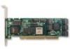
... SATA Connectors Note: For details about LED connectors, see page 17. Oddnumbered ports are usually double-stacked connectors. Figure 1. 8-Port 3ware 9550SX-8LP Serial ATA RAID Controller I2C connector Odd-numbered ports 1 through 4. On the 8-port controller shown below, ports 6 and 7 are located below even-numbered ports. Ports 6 and 7 (top only) Ports: 4 and 5 2 and 3 0 and 1 Slots...
... SATA Connectors Note: For details about LED connectors, see page 17. Oddnumbered ports are usually double-stacked connectors. Figure 1. 8-Port 3ware 9550SX-8LP Serial ATA RAID Controller I2C connector Odd-numbered ports 1 through 4. On the 8-port controller shown below, ports 6 and 7 are located below even-numbered ports. Ports 6 and 7 (top only) Ports: 4 and 5 2 and 3 0 and 1 Slots...
Quick Installation Guide
Page 13
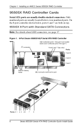
...to connect the first cable. To connect SATA cables to the controller Note: If you have a different model of controller, the location of the ports will be inserted in this section show a 9550SX-8LP. This helps to ensure proper orientation and installation 2 Decide to...provided with the 3ware SATA RAID controller. For details, see the illustrations on page 6 through page 8. www.3ware.com 9 For location of each SATA cable connector is keyed so that it on all boards, see "Chapter 2. Installing a Serial ATA RAID Controller Installing a Serial ATA RAID Controller Note: The ...
...to connect the first cable. To connect SATA cables to the controller Note: If you have a different model of controller, the location of the ports will be inserted in this section show a 9550SX-8LP. This helps to ensure proper orientation and installation 2 Decide to...provided with the 3ware SATA RAID controller. For details, see the illustrations on page 6 through page 8. www.3ware.com 9 For location of each SATA cable connector is keyed so that it on all boards, see "Chapter 2. Installing a Serial ATA RAID Controller Installing a Serial ATA RAID Controller Note: The ...
Quick Installation Guide
Page 21
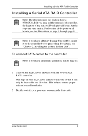
... location of LED indicators on J7: 0, 1, 2, 3 (left to right) Figure 16. 4-Port 3ware 9550SX-4LP Serial ATA RAID Controller LED indicators for individual drives on J7 and J8 Overall LED drive status indicator: the last two pins of J7 and J8. Figure 15. 8-Port 3ware 9550SX-8LP Serial ATA RAID Controller LED indicators for individual drives on the different...
... location of LED indicators on J7: 0, 1, 2, 3 (left to right) Figure 16. 4-Port 3ware 9550SX-4LP Serial ATA RAID Controller LED indicators for individual drives on J7 and J8 Overall LED drive status indicator: the last two pins of J7 and J8. Figure 15. 8-Port 3ware 9550SX-8LP Serial ATA RAID Controller LED indicators for individual drives on the different...
Quick Installation Guide
Page 24
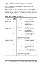
Chapter 1. Do not connect any cathode pins on the bottom 20 3ware 9550SX Serial ATA RAID Controller Quick Install Guide Table 1: LED Indicator Pin Positions Controller LED Header Pin Pair Comment 9550SX-4LP J7 : : : : : Orientation Horizontal 9550SX-8LP J7 J8 0 1 2 3 All Port number/All (all activity... indicator) k-cathode-minus is on the top a-anode-plus is on the controller. Installing an AMCC 3ware 9550SX RAID Controller Table 1 summarizes the LED indicator pin positions for the different controllers. Warning: If using a chassis that has a common or shared LED ground...
Chapter 1. Do not connect any cathode pins on the bottom 20 3ware 9550SX Serial ATA RAID Controller Quick Install Guide Table 1: LED Indicator Pin Positions Controller LED Header Pin Pair Comment 9550SX-4LP J7 : : : : : Orientation Horizontal 9550SX-8LP J7 J8 0 1 2 3 All Port number/All (all activity... indicator) k-cathode-minus is on the top a-anode-plus is on the controller. Installing an AMCC 3ware 9550SX RAID Controller Table 1 summarizes the LED indicator pin positions for the different controllers. Warning: If using a chassis that has a common or shared LED ground...
