Installation Guide
Page 3
...Drives 20 Step 3. Connect the Cables to the Controller 16 Step 1 (Multi-lane Controllers). Table of this Package 1 System Requirements 2 9650SE RAID Controller Card Models 4 Cables 7 Safety Information 10 Chapter 2. Connect Cables to the Controller . . . 17 Step 2. Connect the Cables to the ...SATA/SAS Drive Multi-Lane Backplane . 21 Step 4. Installing Your 3ware RAID Controller 15 Tools You Need 15 Before You Start 15 Step 1 (9650SE-...
...Drives 20 Step 3. Connect the Cables to the Controller 16 Step 1 (Multi-lane Controllers). Table of this Package 1 System Requirements 2 9650SE RAID Controller Card Models 4 Cables 7 Safety Information 10 Chapter 2. Connect Cables to the Controller . . . 17 Step 2. Connect the Cables to the ...SATA/SAS Drive Multi-Lane Backplane . 21 Step 4. Installing Your 3ware RAID Controller 15 Tools You Need 15 Before You Start 15 Step 1 (9650SE-...
Installation Guide
Page 8
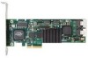
...Getting Started Other Requirements „ Adequate air flow and cooling „ Adequate power supply for drives „ 3DM 2 (3ware Disk Manager), a browser-based application used to configure and maintain RAID units, requires one of the following browsers: „ Internet Explorer 5.5 and later „ Mozilla Firefox 1.2 and later &#... „ For best viewing, screen resolution should be 1024 x 768 or greater, with 16-bit color or greater. 9650SE RAID Controller Card Models Figure 1. 2-Port 3ware 9650SE-2LP Serial ATA RAID Controller LED Connector Heat Sink Ports: 0 (on top) 1 (on the bottom...
...Getting Started Other Requirements „ Adequate air flow and cooling „ Adequate power supply for drives „ 3DM 2 (3ware Disk Manager), a browser-based application used to configure and maintain RAID units, requires one of the following browsers: „ Internet Explorer 5.5 and later „ Mozilla Firefox 1.2 and later &#... „ For best viewing, screen resolution should be 1024 x 768 or greater, with 16-bit color or greater. 9650SE RAID Controller Card Models Figure 1. 2-Port 3ware 9650SE-2LP Serial ATA RAID Controller LED Connector Heat Sink Ports: 0 (on top) 1 (on the bottom...
Installation Guide
Page 9
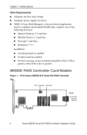
9650SE RAID Controller Card Models Figure 2. 4-Port 3ware 9650SE-4LPML Serial ATA RAID Controller I2C connector LED Connector Heat Sink Ports: 0 thru 3 Slots for battery holder BBU connector and hole for post Figure 3. 8-Port 3ware 9650SE-8LPML Serial ATA RAID Controller I2C connector LED Connectors Heat Sink Ports: 4 thru 7 0 thru 3 Slots for battery BBU connector and hole for post www.3ware.com 5
9650SE RAID Controller Card Models Figure 2. 4-Port 3ware 9650SE-4LPML Serial ATA RAID Controller I2C connector LED Connector Heat Sink Ports: 0 thru 3 Slots for battery holder BBU connector and hole for post Figure 3. 8-Port 3ware 9650SE-8LPML Serial ATA RAID Controller I2C connector LED Connectors Heat Sink Ports: 4 thru 7 0 thru 3 Slots for battery BBU connector and hole for post www.3ware.com 5
Installation Guide
Page 14
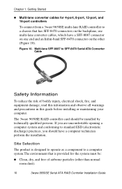
...be installed by technically qualified persons. The 3ware 9650SE RAID controller card should have a SFF-8087 connector on one end and an Infini-band SFF-8470 connector on the other than normal room dust). 10 3ware 9650SE Serial ATA RAID Controller Installation Guide Multi-lane SFF-8087 to... system and conforming to a chassis that is provided for 4-port, 8-port, 12-port, and 16-port controllers To connect from a 3ware 9650SE multi-lane RAID controller to standard ESD (electrostatic discharge) practices, you should be : „ Clean, dry, and free of bodily injury, electrical shock...
...be installed by technically qualified persons. The 3ware 9650SE RAID controller card should have a SFF-8087 connector on one end and an Infini-band SFF-8470 connector on the other than normal room dust). 10 3ware 9650SE Serial ATA RAID Controller Installation Guide Multi-lane SFF-8087 to... system and conforming to a chassis that is provided for 4-port, 8-port, 12-port, and 16-port controllers To connect from a 3ware 9650SE multi-lane RAID controller to standard ESD (electrostatic discharge) practices, you should be : „ Clean, dry, and free of bodily injury, electrical shock...
Installation Guide
Page 17
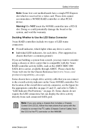
... If you are using a chassis or drive carrier that is reserved for a video card. www.3ware.com 13 Some chassis have a single drive activity cable that came with the 3ware RAID controller activity LEDs, such as the AMCC RDC-400SATA drive carrier, available through AMCC.... you may want to Table 2, "LED Indicator Pin Positions," on the 3ware 9650SE controller. These slots cannot accommodate a 9650SE RAID controller or other PCI-E device. Safety Information Note: Some low-cost motherboards have a single PCI Express slot which lights when any drive is active. „ Individual LED...
... If you are using a chassis or drive carrier that is reserved for a video card. www.3ware.com 13 Some chassis have a single drive activity cable that came with the 3ware RAID controller activity LEDs, such as the AMCC RDC-400SATA drive carrier, available through AMCC.... you may want to Table 2, "LED Indicator Pin Positions," on the 3ware 9650SE controller. These slots cannot accommodate a 9650SE RAID controller or other PCI-E device. Safety Information Note: Some low-cost motherboards have a single PCI Express slot which lights when any drive is active. „ Individual LED...
Installation Guide
Page 22
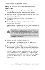
... 3ware 9650SE Serial ATA RAID Controller Installation Guide Warning! Only the 3ware 9650SE-2LP RAID controller will be used to secure the 3ware RAID controller after you are properly grounded. (For details about which slot to use , see "Selecting the Slot in the Computer 1 If the computer is running, shut it in the slot. 6 Position the card in the PCI...
... 3ware 9650SE Serial ATA RAID Controller Installation Guide Warning! Only the 3ware 9650SE-2LP RAID controller will be used to secure the 3ware RAID controller after you are properly grounded. (For details about which slot to use , see "Selecting the Slot in the Computer 1 If the computer is running, shut it in the slot. 6 Position the card in the PCI...

Installation Guide
Page 23
... doubt about what slots you have, check the documentation for the 3ware 9650SE controller. Inserting Controller Into PCI Express Slot Do NOT use a PCI or PCI-X slot. Figure 13. Use a PCI Express slot for your motherboard. 8 Check that the 3ware RAID controller's metal bracket covers the hole in the case and secure ... to the enclosure, make sure the card is not slanted in the Computer 7 Press down gently on the edge of the 3ware RAID controller directly above the PCI Express slot until it is fully seated. www.3ware.com 19 otherwise the card will not work properly. Install the ...
... doubt about what slots you have, check the documentation for the 3ware 9650SE controller. Inserting Controller Into PCI Express Slot Do NOT use a PCI or PCI-X slot. Figure 13. Use a PCI Express slot for your motherboard. 8 Check that the 3ware RAID controller's metal bracket covers the hole in the case and secure ... to the enclosure, make sure the card is not slanted in the Computer 7 Press down gently on the edge of the 3ware RAID controller directly above the PCI Express slot until it is fully seated. www.3ware.com 19 otherwise the card will not work properly. Install the ...
Installation Guide
Page 29
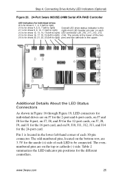
Step 4. Connecting Drive Activity LED Indicators (Optional) Figure 20. 24-Port 3ware 9650SE-24M8 Serial ATA RAID Controller LED indicators for individual drives J9 is for drives 0, 1, 2, 3 (left to right) J10 is for drives 4, 5, 6, 7 (left to right) Overall LED drive status indicator ... pair on the top or cathode (-) side. The odd-numbered pins, located on the bottom row, are on each J12 is for the 24-port card. Table 2 summarizes the LED indicator pin positions for drives 20, 21, 22, 23 (left -hand corner of each 10-pin connector. Additional Details About the...
Step 4. Connecting Drive Activity LED Indicators (Optional) Figure 20. 24-Port 3ware 9650SE-24M8 Serial ATA RAID Controller LED indicators for individual drives J9 is for drives 0, 1, 2, 3 (left to right) J10 is for drives 4, 5, 6, 7 (left to right) Overall LED drive status indicator ... pair on the top or cathode (-) side. The odd-numbered pins, located on the bottom row, are on each J12 is for the 24-port card. Table 2 summarizes the LED indicator pin positions for drives 20, 21, 22, 23 (left -hand corner of each 10-pin connector. Additional Details About the...

Installation Guide
Page 33
...Do not touch any pin, contact, lead, or component on an ESD-protective mat. „ Do not remove the 3ware controller or BBU from components that can be attached to a 3ware 9650SE RAID controller to supply power to the memory module from an attached battery pack in the event of time (up to... use write-caching for a limited period of a system power loss. Important: The battery is flushed to data loss in the system, such as video cards. When installing...
...Do not touch any pin, contact, lead, or component on an ESD-protective mat. „ Do not remove the 3ware controller or BBU from components that can be attached to a 3ware 9650SE RAID controller to supply power to the memory module from an attached battery pack in the event of time (up to... use write-caching for a limited period of a system power loss. Important: The battery is flushed to data loss in the system, such as video cards. When installing...