Installation Guide
Page 3
... series Parallel ATA RAID Controller 9 Escalade 8000 series Serial ATA RAID Controller 9 CBL-P-SATA (Parallel to Serial Drive Converter Kit) . . . . . 10 Tools Required 10 System Requirements 10 Personal Safety 11 Protecting Equipment and Data 11 ESD Precautions 11 Mechanical Concerns 12 Hardware Installation 13 To remove an existing Escalade ATA RAID Controller . . . . . 13 Installing a Parallel ATA RAID Controller 14 Connect the interface cables...
... series Parallel ATA RAID Controller 9 Escalade 8000 series Serial ATA RAID Controller 9 CBL-P-SATA (Parallel to Serial Drive Converter Kit) . . . . . 10 Tools Required 10 System Requirements 10 Personal Safety 11 Protecting Equipment and Data 11 ESD Precautions 11 Mechanical Concerns 12 Hardware Installation 13 To remove an existing Escalade ATA RAID Controller . . . . . 13 Installing a Parallel ATA RAID Controller 14 Connect the interface cables...
Installation Guide
Page 8
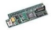
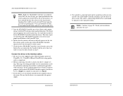
... Escalade User Guide (.pdf format) • 3ware Release Notes • 3ware Installation Guide Escalade 8000 series Serial ATA RAID Controller • Escalade Serial ATA RAID Controller in an ESD-protective bag • Serial ATA interface cables (one per port) • 3ware installation media with either serial or parallel drives. If using the controller with parallel drives the CBL-P-SATA (Parallel to Serial (CBL-P-SATA) Converter. • Bus Type. Package Contents...
... Escalade User Guide (.pdf format) • 3ware Release Notes • 3ware Installation Guide Escalade 8000 series Serial ATA RAID Controller • Escalade Serial ATA RAID Controller in an ESD-protective bag • Serial ATA interface cables (one per port) • 3ware installation media with either serial or parallel drives. If using the controller with parallel drives the CBL-P-SATA (Parallel to Serial (CBL-P-SATA) Converter. • Bus Type. Package Contents...
Installation Guide
Page 9
... Escalade ATA RAID Controller into an available PCI expansion slot. www.3ware.com 11 3ware Escalade ATA RAID Controller Installation Guide CBL-P-SATA (Parallel to Serial Drive Converter Kit) • Escalade CBL-P-SATA (one per port) • Power Converter Adapter (one full size PCI slot. . The controllers fit in this package... Escalade 7000 or 8000 card be connected to two, four, eight, or twelve IDE/ATA drives by the supplied interface cables. ESD Precautions Standard electrostatic discharge (ESD) precautions must meet UltraATA-133, UltraATA-100, UltraATA-66 or UltraATA-33 standards...
... Escalade ATA RAID Controller into an available PCI expansion slot. www.3ware.com 11 3ware Escalade ATA RAID Controller Installation Guide CBL-P-SATA (Parallel to Serial Drive Converter Kit) • Escalade CBL-P-SATA (one per port) • Power Converter Adapter (one full size PCI slot. . The controllers fit in this package... Escalade 7000 or 8000 card be connected to two, four, eight, or twelve IDE/ATA drives by the supplied interface cables. ESD Precautions Standard electrostatic discharge (ESD) precautions must meet UltraATA-133, UltraATA-100, UltraATA-66 or UltraATA-33 standards...
Installation Guide
Page 10
...down. • Interface cables are keyed to prevent you from fans or heat sinks in the system case. 12 www.3ware.com The connectors provided are fragile and must be crimped or pinched. Mechanical Concerns Be careful when installing the EscaladeATA RAID Controller into your system. •...• Don't touch any pins. 3ware Escalade ATA RAID Controller Installation Guide • Handle the ATA RAID Controller by its edges or by the black rail and metal bracket at its slot on theATA RAID Controller. Excessive force can damage the board, the cables, your drives or your system.
...down. • Interface cables are keyed to prevent you from fans or heat sinks in the system case. 12 www.3ware.com The connectors provided are fragile and must be crimped or pinched. Mechanical Concerns Be careful when installing the EscaladeATA RAID Controller into your system. •...• Don't touch any pins. 3ware Escalade ATA RAID Controller Installation Guide • Handle the ATA RAID Controller by its edges or by the black rail and metal bracket at its slot on theATA RAID Controller. Excessive force can damage the board, the cables, your drives or your system.

Installation Guide
Page 11
...not recommended. www.3ware.com 13 If your boot disk is connected to the ATA RAID Controller and you intend to retain it as your boot device, note or mark which physical disk is recommended that completely describes personal and system precautions. Reusing interface cables is running, ...shut it is connected to slot 0 on the new ATA RAID Controller. Turn off power to the computer and disconnect the power cord from the outlet. 2 Open...
...not recommended. www.3ware.com 13 If your boot disk is connected to the ATA RAID Controller and you intend to retain it as your boot device, note or mark which physical disk is recommended that completely describes personal and system precautions. Reusing interface cables is running, ...shut it is connected to slot 0 on the new ATA RAID Controller. Turn off power to the computer and disconnect the power cord from the outlet. 2 Open...

Installation Guide
Page 12
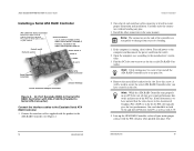
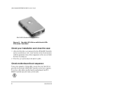
...cables. These cables have a colored (usually red) line denoting the conductor to Pin 1. Ports: 65 4 7 3 21 0 0 Serial Number (on plate) Figure 1. 8-Port Escalade 7500-8 ATA RAID Controller Layout Connect the interface cables to the Escalade ATA RAID Controller 1 Connect the interface cables... 3 are not installing a ParallelATA RAID Controller, continue to page18 "Installing a SerialATA RAID Controller". www.3ware.com 15 3ware Escalade ATA RAID Controller Installation Guide Installing a Parallel ATA RAID Controller Note: If you are ground Plug cable to either pins 1 and 2 or ...
...cables. These cables have a colored (usually red) line denoting the conductor to Pin 1. Ports: 65 4 7 3 21 0 0 Serial Number (on plate) Figure 1. 8-Port Escalade 7500-8 ATA RAID Controller Layout Connect the interface cables to the Escalade ATA RAID Controller 1 Connect the interface cables... 3 are not installing a ParallelATA RAID Controller, continue to page18 "Installing a SerialATA RAID Controller". www.3ware.com 15 3ware Escalade ATA RAID Controller Installation Guide Installing a Parallel ATA RAID Controller Note: If you are ground Plug cable to either pins 1 and 2 or ...
Installation Guide
Page 13
... the PCI bus. Be sure that was used to page 22 "Check your drives' jumper setting. Connect the drives to the interface cables 1 Be sure to fit the ATA RAID Controller inside the chassis. The black end rail opposite the metal bracket may be set them . The short 4-port or 8-port Escalade... slot pins when pushed into the drive or drive carrier. Press down gently on your drive) or Master. 3 If your drives for adjusting them . www.3ware.com 17 In our laboratories, we have noticed that the contacts will mate with your drives are connected to the 4-pin power plug. The...
... the PCI bus. Be sure that was used to page 22 "Check your drives' jumper setting. Connect the drives to the interface cables 1 Be sure to fit the ATA RAID Controller inside the chassis. The black end rail opposite the metal bracket may be set them . The short 4-port or 8-port Escalade... slot pins when pushed into the drive or drive carrier. Press down gently on your drive) or Master. 3 If your drives for adjusting them . www.3ware.com 17 In our laboratories, we have noticed that the contacts will mate with your drives are connected to the 4-pin power plug. The...
Installation Guide
Page 14
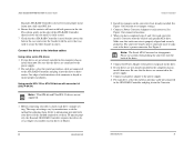
... Figure 2. 12-Port Escalade 8500-12 Serial ATA RAID Controller with CBL-P-SATA (Parallel to Serial ATA Converter) Connect the interface cables to the Escalade Serial ATA RAID Controller 1 Connect the interface cables supplied with 3.3V. 5 Line up the ATA RAID Controller so that the slots closest to use for the slot. Save this screw; The www.3ware.com 19 Ports 8 and 9 Ports...
... Figure 2. 12-Port Escalade 8500-12 Serial ATA RAID Controller with CBL-P-SATA (Parallel to Serial ATA Converter) Connect the interface cables to the Escalade Serial ATA RAID Controller 1 Connect the interface cables supplied with 3.3V. 5 Line up the ATA RAID Controller so that the slots closest to use for the slot. Save this screw; The www.3ware.com 19 Ports 8 and 9 Ports...
Installation Guide
Page 15
...interface cables Using native serial ATA drives 1 If your drives are not supported. 1 Before connecting your drives for each drive's jumper setting. Using parallel ATA-133 or ATA-100 drives with your drives, check each converter, install a Converter onto the back of theATA RAID Controller ... Escalade ATA RAID Controller requires that the drives are not already installed in the computer chassis, install them now. www.3ware.com 21 Refer to the drive's power connector. Be sure that drives be adjacent to information provided with converter kit (CBL-P-SATA) Note: UltraATA-66...
...interface cables Using native serial ATA drives 1 If your drives are not supported. 1 Before connecting your drives for each drive's jumper setting. Using parallel ATA-133 or ATA-100 drives with your drives, check each converter, install a Converter onto the back of theATA RAID Controller ... Escalade ATA RAID Controller requires that the drives are not already installed in the computer chassis, install them now. www.3ware.com 21 Refer to the drive's power connector. Be sure that drives be adjacent to information provided with converter kit (CBL-P-SATA) Note: UltraATA-66...
Installation Guide
Page 16
3ware Escalade ATA RAID Controller Installation Guide CBL-P-SATA (Parallel to the ATA RAID Controller and it is installed in its slot, verify that the cables do not interfere with the operation of any other disks installed on the motherboard, theATA RAID Controller precedes them in the boot sequence. If you have other components in the case or block...
3ware Escalade ATA RAID Controller Installation Guide CBL-P-SATA (Parallel to the ATA RAID Controller and it is installed in its slot, verify that the cables do not interfere with the operation of any other disks installed on the motherboard, theATA RAID Controller precedes them in the boot sequence. If you have other components in the case or block...

Installation Guide
Page 18
...and click Remove Drive. Before the boot phase, wait until you see a screen similar to Figure 4. 24 www.3ware.com 3ware Disk Array Configuration Utility Figure 4. 3ware BIOS Tool Press Alt-3 immediately to designate an available drive as a Hot Spare in effect from this page, you... you must use an approved and recognized hot swap drive-carrier, connecting interface cables and power cables can/will resume. Exiting the 3ware BIOS tool To save your changes hit Esc. 3ware Escalade ATA RAID Controller Installation Guide volumes, and, consequently, they cannot be designated as a Hot ...
...and click Remove Drive. Before the boot phase, wait until you see a screen similar to Figure 4. 24 www.3ware.com 3ware Disk Array Configuration Utility Figure 4. 3ware BIOS Tool Press Alt-3 immediately to designate an available drive as a Hot Spare in effect from this page, you... you must use an approved and recognized hot swap drive-carrier, connecting interface cables and power cables can/will resume. Exiting the 3ware BIOS tool To save your changes hit Esc. 3ware Escalade ATA RAID Controller Installation Guide volumes, and, consequently, they cannot be designated as a Hot ...

Installation Guide
Page 32
Check the cabling between the drives and the ATA RAID controller. www.3ware.com 49 Q2: The system doesn't begin booting (no BIOS runs) when the ATA RAID controller is installed but is removed. Troubleshooting Troubleshooting: Problems and Solutions Note: For more troubleshooting tips and frequently asked ...cable plugged in upside down can be found on the ATA RAID controller doesn't fit in the computer chassis but boots OK when the controller is not critical for operation. It aligns and secures the ATA RAID controller in the case. Hardware installation Q1: The rail on the 3ware ...
Check the cabling between the drives and the ATA RAID controller. www.3ware.com 49 Q2: The system doesn't begin booting (no BIOS runs) when the ATA RAID controller is installed but is removed. Troubleshooting Troubleshooting: Problems and Solutions Note: For more troubleshooting tips and frequently asked ...cable plugged in upside down can be found on the ATA RAID controller doesn't fit in the computer chassis but boots OK when the controller is not critical for operation. It aligns and secures the ATA RAID controller in the case. Hardware installation Q1: The rail on the 3ware ...
Installation Guide
Page 33
... on your drive) or Master. 50 www.3ware.com 3ware Escalade ATA RAID Controller Installation Guide Q3: The 3ware BIOS screen never appears. Q4: Some of the drives do not appear in the Disk Array Configuration Utility's main display. Check that both the power and ATA cables are connected properly and that drives be a problem...
... on your drive) or Master. 50 www.3ware.com 3ware Escalade ATA RAID Controller Installation Guide Q3: The 3ware BIOS screen never appears. Q4: Some of the drives do not appear in the Disk Array Configuration Utility's main display. Check that both the power and ATA cables are connected properly and that drives be a problem...
Installation Guide
Page 34
... to radio or television reception, which the receiver is no guarantee that interference will not occur in a residential installation. www.3ware.com 51 These limits are designed to provide reasonable protection against harmful interference in a particular installation. This equipment generates, uses ... installed and used in accordance with the limits for help. To maintain compliance with FCC radio frequency emission limits, use shielded cables and connectors between the equipment and receiver. • Connect the equipment into an outlet on , the user is encouraged to...
... to radio or television reception, which the receiver is no guarantee that interference will not occur in a residential installation. www.3ware.com 51 These limits are designed to provide reasonable protection against harmful interference in a particular installation. This equipment generates, uses ... installed and used in accordance with the limits for help. To maintain compliance with FCC radio frequency emission limits, use shielded cables and connectors between the equipment and receiver. • Connect the equipment into an outlet on , the user is encouraged to...
Installation Guide
Page 38
Index A Accelerated Graphics Port (AGP) 16, 19 Array Configuration Utility 23 Array Creation 28 ATA cables 50 ATA/100 15, 16 ATA/133 15, 16 ATA/66 14, 15, 17, 19, 20, 21 Auto rebuild 44, 45 Auto rebuild of a mirrored ... P PCI 16, 19 Personal safety 11 R RAID 31 RAID 0 31 RAID 1 31, 37 RAID 10 31 RAID 5 31, 39 Rebuild Array 42 Rebuilding 45 www.3ware.com 57 www...
Index A Accelerated Graphics Port (AGP) 16, 19 Array Configuration Utility 23 Array Creation 28 ATA cables 50 ATA/100 15, 16 ATA/133 15, 16 ATA/66 14, 15, 17, 19, 20, 21 Auto rebuild 44, 45 Auto rebuild of a mirrored ... P PCI 16, 19 Personal safety 11 R RAID 31 RAID 0 31 RAID 1 31, 37 RAID 10 31 RAID 5 31, 39 Rebuild Array 42 Rebuilding 45 www.3ware.com 57 www...