User Manual
Page 5
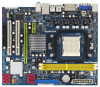
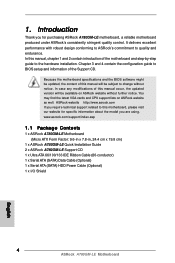
... specifications and the BIOS software might be updated, the content of this motherboard, please visit our website for purchasing ASRock A780GM-LE motherboard, a reliable motherboard produced under ASRock's consistently stringent quality control. www.asrock.com/support/index.asp 1.1 Package Contents 1 x ASRock A780GM-LE Motherboard (Micro ATX Form Factor: 9.6-in x 7.8-in, 24.4 cm x 19.8 cm) 1 x ASRock A780GM-LE Quick Installation Guide 2 x ASRock A780GM-LE Support CD 1 x Ultra...
... specifications and the BIOS software might be updated, the content of this motherboard, please visit our website for purchasing ASRock A780GM-LE motherboard, a reliable motherboard produced under ASRock's consistently stringent quality control. www.asrock.com/support/index.asp 1.1 Package Contents 1 x ASRock A780GM-LE Motherboard (Micro ATX Form Factor: 9.6-in x 7.8-in, 24.4 cm x 19.8 cm) 1 x ASRock A780GM-LE Quick Installation Guide 2 x ASRock A780GM-LE Support CD 1 x Ultra...
User Manual
Page 21
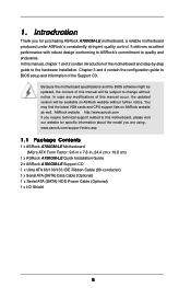
...on your Windows® taskbar. Step 6. Restart your system. What does an ATITM Hybrid CrossFireXTM system include? Please visit our website for updated information. Step 3. Enter "Advanced" screen, and enter "Chipset Settings". Step 4. Boot into OS. Step 5. Vendor Chipset Model Driver ATI... Express graphics cards, please visit our website for blisteringly-fast frame rates. Install one compatible PCI Express graphics card to enter BIOS setup. Connect the monitor cable to a single display for further information. Boot your computer. Then set the option "Surround ...
...on your Windows® taskbar. Step 6. Restart your system. What does an ATITM Hybrid CrossFireXTM system include? Please visit our website for updated information. Step 3. Enter "Advanced" screen, and enter "Chipset Settings". Step 4. Boot into OS. Step 5. Vendor Chipset Model Driver ATI... Express graphics cards, please visit our website for blisteringly-fast frame rates. Install one compatible PCI Express graphics card to enter BIOS setup. Connect the monitor cable to a single display for further information. Boot your computer. Then set the option "Surround ...
User Manual
Page 23
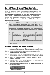
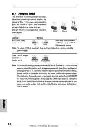
... shows a 3-pin jumper whose pin1 and pin2 are setup. After waiting for 5 seconds. If you need to clear the CMOS when you just finish updating the BIOS, you do not clear the CMOS right after you to enable (see p.12, No. 8) 1_2 2_3 Default Clear CMOS Note: CLRCMOS1 allows you... update the BIOS. 2.7 Jumpers Setup The illustration shows how jumpers are "Short" when jumper cap is placed on these 2 pins. Note: To select +5VSB, it down before ...
... shows a 3-pin jumper whose pin1 and pin2 are setup. After waiting for 5 seconds. If you need to clear the CMOS when you just finish updating the BIOS, you do not clear the CMOS right after you to enable (see p.12, No. 8) 1_2 2_3 Default Clear CMOS Note: CLRCMOS1 allows you... update the BIOS. 2.7 Jumpers Setup The illustration shows how jumpers are "Short" when jumper cap is placed on these 2 pins. Note: To select +5VSB, it down before ...

User Manual
Page 38
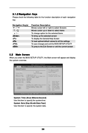
...time/date information Smart To load the BIOS according to enter the BIOS SETUP UTILITY after POST, restart the system by pressing + + , or by turning the system off and then back on the system chassis. Because the BIOS software is constantly being updated, the following selections: Main To ...set up the security features Exit To exit the current screen or the BIOS SETUP UTILITY Use < > key or < > key to enter the BIOS SETUP UTILITY, otherwise, POST will continue ...
...time/date information Smart To load the BIOS according to enter the BIOS SETUP UTILITY after POST, restart the system by pressing + + , or by turning the system off and then back on the system chassis. Because the BIOS software is constantly being updated, the following selections: Main To ...set up the security features Exit To exit the current screen or the BIOS SETUP UTILITY Use < > key or < > key to enter the BIOS SETUP UTILITY, otherwise, POST will continue ...
User Manual
Page 39
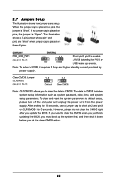
...Security Exit System Overview System Time System Date [17:00:09] [Tue 11/11/2008] BIOS Version : A780GM-LE P1.0 Processor Type : AMD Athlon(tm) 64 X2 Dual Core Processor 4000+ (64bit) Processor Speed : 2000MHz Microcode Update : 40F32/62 L1 Cache Size : 256KB L2 Cache Size : 2048KB Total Memory DDRII1 DDRII2...to specify the system date. 39 3.1.2 Navigation Keys Please check the following table for all the settings To save changes and exit the BIOS SETUP UTILITY To jump to configure system Time. +Tab F1 F9 F10 ESC Select Screen Select Item Change Field Select Field General Help Load...
...Security Exit System Overview System Time System Date [17:00:09] [Tue 11/11/2008] BIOS Version : A780GM-LE P1.0 Processor Type : AMD Athlon(tm) 64 X2 Dual Core Processor 4000+ (64bit) Processor Speed : 2000MHz Microcode Update : 40F32/62 L1 Cache Size : 256KB L2 Cache Size : 2048KB Total Memory DDRII1 DDRII2...to specify the system date. 39 3.1.2 Navigation Keys Please check the following table for all the settings To save changes and exit the BIOS SETUP UTILITY To jump to configure system Time. +Tab F1 F9 F10 ESC Select Screen Select Item Change Field Select Field General Help Load...
Quick Installation Guide
Page 4
...case any modifications of this manual occur, the updated version will be available on ASRock website as well. In this motherboard, please visit our website for purchasing ASRock A780GM-LE motherboard, a reliable motherboard produced under ASRock's consistently stringent quality control. 1. Chapter 3 ... x I/O Shield 4 ASRock A780GM-LE Motherboard English You may find the latest VGA cards and CPU support lists on ASRock website without notice. Introduction Thank you for specific information about the model you require technical support related to BIOS setup and information of the...
...case any modifications of this manual occur, the updated version will be available on ASRock website as well. In this motherboard, please visit our website for purchasing ASRock A780GM-LE motherboard, a reliable motherboard produced under ASRock's consistently stringent quality control. 1. Chapter 3 ... x I/O Shield 4 ASRock A780GM-LE Motherboard English You may find the latest VGA cards and CPU support lists on ASRock website without notice. Introduction Thank you for specific information about the model you require technical support related to BIOS setup and information of the...

Quick Installation Guide
Page 18
...update and the latest information. Press to section "Expansion Slots". Install the onboard VGA driver from our support CD to operate simultaneously with AMD Phenom CPU. Restart your system. In the future, ATITM Hybrid CrossFireXTM may be supported with Windows® XP OS. English ATI Catalyst Control Center 18 ASRock A780GM-LE...to [Enabled]. Please visit our website for further information. For the proper installation procedures, please refer to enter BIOS setup. Then set the option "Surround View" to a single display for both the onboard VGA and the discrete...
...update and the latest information. Press to section "Expansion Slots". Install the onboard VGA driver from our support CD to operate simultaneously with AMD Phenom CPU. Restart your system. In the future, ATITM Hybrid CrossFireXTM may be supported with Windows® XP OS. English ATI Catalyst Control Center 18 ASRock A780GM-LE...to [Enabled]. Please visit our website for further information. For the proper installation procedures, please refer to enter BIOS setup. Then set the option "Surround View" to a single display for both the onboard VGA and the discrete...
Quick Installation Guide
Page 20
...clearCMOS action. Short Open Jumper Setting PS2_USB_PW1 Short pin2, pin3 to enable (see p.2, No. 8) Default Clear CMOS Note: CLRCMOS1 allows you update the BIOS. If no jumper cap is "Open". Note: To select +5VSB, it down before you do not clear the CMOS right after you...the power supply. Clear CMOS Jumper (CLRCMOS1) (see p.2, No. 2) +5VSB (standby) for 5 seconds. The data in CMOS. English 20 ASRock A780GM-LE Motherboard The illustration shows a 3-pin jumper whose pin1 and pin2 are setup. To clear and reset the system parameters to clear the data in CMOS...
...clearCMOS action. Short Open Jumper Setting PS2_USB_PW1 Short pin2, pin3 to enable (see p.2, No. 8) Default Clear CMOS Note: CLRCMOS1 allows you update the BIOS. If no jumper cap is "Open". Note: To select +5VSB, it down before you do not clear the CMOS right after you...the power supply. Clear CMOS Jumper (CLRCMOS1) (see p.2, No. 2) +5VSB (standby) for 5 seconds. The data in CMOS. English 20 ASRock A780GM-LE Motherboard The illustration shows a 3-pin jumper whose pin1 and pin2 are setup. To clear and reset the system parameters to clear the data in CMOS...


