User Manual
Page 12
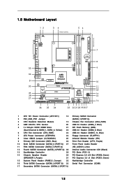
...11 Fifth SATAII Connector (SATAII_5 (PORT 4)) (HD_AUDIO1, Lime) 12 Fourth SATAII Connector (SATAII_4 (PORT 3)) 28 Internal Audio Connector: CD1 (Black) 13 Southbridge Controller 29 PCI Slots (PCI1- 2) 14 Chassis Speaker Header 30 PCI Express 2.0 x16 Slot (PCIE2; 1.5 Motherboard Layout PS2 ...IN Center: FRONT Bottom: MIC IN LAN AUDIO CODEC PCIE1 Super I/O CD1 1 HD_AUDIO1 LPT1 1 IR1 1 FLOPPY1 AMD 780G Chipset IDE1 RoHS PCIE2 A780GM-LE PCI1 PCI2 USB10_11 1 8Mb BIOS USB8_9 1 SATAII_4 SATAII_5 SATAII_6 (PORT 3) (PORT 4) (PORT 5) AMD SB710 / SB700 Chipset SPEAKER1 1 PLED ...
...11 Fifth SATAII Connector (SATAII_5 (PORT 4)) (HD_AUDIO1, Lime) 12 Fourth SATAII Connector (SATAII_4 (PORT 3)) 28 Internal Audio Connector: CD1 (Black) 13 Southbridge Controller 29 PCI Slots (PCI1- 2) 14 Chassis Speaker Header 30 PCI Express 2.0 x16 Slot (PCIE2; 1.5 Motherboard Layout PS2 ...IN Center: FRONT Bottom: MIC IN LAN AUDIO CODEC PCIE1 Super I/O CD1 1 HD_AUDIO1 LPT1 1 IR1 1 FLOPPY1 AMD 780G Chipset IDE1 RoHS PCIE2 A780GM-LE PCI1 PCI2 USB10_11 1 8Mb BIOS USB8_9 1 SATAII_4 SATAII_5 SATAII_6 (PORT 3) (PORT 4) (PORT 5) AMD SB710 / SB700 Chipset SPEAKER1 1 PLED ...
User Manual
Page 24
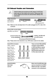
Primary IDE connector (Blue) (39-pin IDE1, see p.12 No. 9) PIN1 IDE1 connect the blue end to the motherboard connect the black end to the IDE devices 80-conductor ATA 66/100/133 cable Note: Please refer to the instruction of the motherboard! • Floppy Connector (33-...
Primary IDE connector (Blue) (39-pin IDE1, see p.12 No. 9) PIN1 IDE1 connect the blue end to the motherboard connect the black end to the IDE devices 80-conductor ATA 66/100/133 cable Note: Please refer to the instruction of the motherboard! • Floppy Connector (33-...
User Manual
Page 25
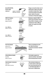
Serial ATA (SATA) Power Cable (Optional) connect to the SATA HDD power connector connect to the power supply Please connect the black end of the power supply. Infrared Module Header (5-pin IR1) (see p.12 No. 26) AFD# ERROR# PINIT# SLIN# GND 1 SPD7 SPD6 ACK# SPD5 BUSY SPD4 ...
Serial ATA (SATA) Power Cable (Optional) connect to the SATA HDD power connector connect to the power supply Please connect the black end of the power supply. Infrared Module Header (5-pin IR1) (see p.12 No. 26) AFD# ERROR# PINIT# SLIN# GND 1 SPD7 SPD6 ACK# SPD5 BUSY SPD4 ...
User Manual
Page 27
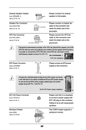
...CHA_FAN_SPEED CPU Fan Connector (4-pin CPU_FAN1) (see p.12 No. 6) 4 3 2 1 GND +12V CPU_FAN_SPEED FAN_SPEED_CONTROL Please connect the chassis speaker to this connector and match the black wire to the ground pin. Please connect a chassis fan cable to this header. To use the 20-pin ATX power supply, please plug your power..., 12 24 it can work if you plan to connect the 3-Pin CPU fan to the CPU fan connector on this connector and match the black wire to this connector. Pin 1-3 Connected 3-Pin Fan Installation ATX Power Connector (24-pin ATXPWR1) (see p.12 No.33) 20-Pin ATX ...
...CHA_FAN_SPEED CPU Fan Connector (4-pin CPU_FAN1) (see p.12 No. 6) 4 3 2 1 GND +12V CPU_FAN_SPEED FAN_SPEED_CONTROL Please connect the chassis speaker to this connector and match the black wire to the ground pin. Please connect a chassis fan cable to this header. To use the 20-pin ATX power supply, please plug your power..., 12 24 it can work if you plan to connect the 3-Pin CPU fan to the CPU fan connector on this connector and match the black wire to this connector. Pin 1-3 Connected 3-Pin Fan Installation ATX Power Connector (24-pin ATXPWR1) (see p.12 No.33) 20-Pin ATX ...
User Manual
Page 31
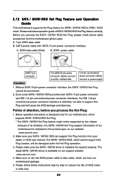
.../ SATAII HDD, which are from our motherboard package. 5. Make sure to reduce the risk of our motherboard is available on our website: www.asrock.com 2. Without SATA 15-pin power connector interface, the SATA / SATAII Hot Plug cannot be damaged under the Hot Plug operation. 3. Make .../ SATAII HDD Hot Plug feature carefully. SATA data cable (Red) B. SATA power cable SATA 7-pin connector The SATA 15-pin power connector (Black) connect to SATA / SATAII HDD 1x4-pin conventional power connector (White) connect to support Hot Plug and will be processed. 2. Please follow ...
.../ SATAII HDD, which are from our motherboard package. 5. Make sure to reduce the risk of our motherboard is available on our website: www.asrock.com 2. Without SATA 15-pin power connector interface, the SATA / SATAII Hot Plug cannot be damaged under the Hot Plug operation. 3. Make .../ SATAII HDD Hot Plug feature carefully. SATA data cable (Red) B. SATA power cable SATA 7-pin connector The SATA 15-pin power connector (Black) connect to SATA / SATAII HDD 1x4-pin conventional power connector (White) connect to support Hot Plug and will be processed. 2. Please follow ...

User Manual
Page 32
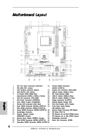
...) to the SATA / SATAII HDD. Step 4 Connect SATA data cable to the power supply 1x4-pin cable. Step 2 Unplug SATA 15-pin power cable connector (Black) from SATA / SATAII HDD side. SATA power cable 1x4-pin power connector (White) Step 3 Connect SATA 15-pin power cable connector... (Black) end to SATA / SATAII HDD. How to Hot Unplug a SATA / SATAII HDD: Points of attention, before you process the Hot Plug: Please do follow below ...
...) to the SATA / SATAII HDD. Step 4 Connect SATA data cable to the power supply 1x4-pin cable. Step 2 Unplug SATA 15-pin power cable connector (Black) from SATA / SATAII HDD side. SATA power cable 1x4-pin power connector (White) Step 3 Connect SATA 15-pin power cable connector... (Black) end to SATA / SATAII HDD. How to Hot Unplug a SATA / SATAII HDD: Points of attention, before you process the Hot Plug: Please do follow below ...
Quick Installation Guide
Page 2
...(PANEL1, Orange) 32 Northbridge Controller 16 Third SATAII Connector (SATAII_3 (PORT 2)) 33 Serial Port Connector (COM1) 17 Secondary SATAII Connector (SATAII_2 (PORT 1)) 2 ASRock A780GM-LE Motherboard Yellow) 22 USB 2.0 Header (USB8_9, Blue) 6 CPU Fan Connector (CPU_FAN1) 23 USB 2.0 Header (USB10_11, Blue) 7 ATX Power Connector (ATXPWR1)...Connector (SATAII_5 (PORT 4)) (HD_AUDIO1, Lime) 12 Fourth SATAII Connector (SATAII_4 (PORT 3)) 28 Internal Audio Connector: CD1 (Black) 13 Southbridge Controller 29 PCI Slots (PCI1- 2) 14 Chassis Speaker Header 30 PCI Express 2.0 x16 Slot (PCIE2;
...(PANEL1, Orange) 32 Northbridge Controller 16 Third SATAII Connector (SATAII_3 (PORT 2)) 33 Serial Port Connector (COM1) 17 Secondary SATAII Connector (SATAII_2 (PORT 1)) 2 ASRock A780GM-LE Motherboard Yellow) 22 USB 2.0 Header (USB8_9, Blue) 6 CPU Fan Connector (CPU_FAN1) 23 USB 2.0 Header (USB10_11, Blue) 7 ATX Power Connector (ATXPWR1)...Connector (SATAII_5 (PORT 4)) (HD_AUDIO1, Lime) 12 Fourth SATAII Connector (SATAII_4 (PORT 3)) 28 Internal Audio Connector: CD1 (Black) 13 Southbridge Controller 29 PCI Slots (PCI1- 2) 14 Chassis Speaker Header 30 PCI Express 2.0 x16 Slot (PCIE2;

Quick Installation Guide
Page 21
... the motherboard connect the black end to the IDE devices 80-conductor ATA 66/100/133 cable Note: Please refer to Pin1 Note: Make sure the red-striped side of the cable is plugged into Pin1 side of your IDE device vendor for internal storage devices. English 21 ASRock A780GM-LE Motherboard Do NOT...
... the motherboard connect the black end to the IDE devices 80-conductor ATA 66/100/133 cable Note: Please refer to Pin1 Note: Make sure the red-striped side of the cable is plugged into Pin1 side of your IDE device vendor for internal storage devices. English 21 ASRock A780GM-LE Motherboard Do NOT...

Quick Installation Guide
Page 22
... a CD-ROM, DVD-ROM, TV tuner card, or MPEG card. 22 ASRock A780GM-LE Motherboard Each USB 2.0 header can support two USB 2.0 ports. (9-pin USB6_7) (see p.2 No. 20) English Print Port Header (25-pin LPT1) (see p.2 No. 22) Please connect the black end of SATA power cable to the power connector on this motherboard...
... a CD-ROM, DVD-ROM, TV tuner card, or MPEG card. 22 ASRock A780GM-LE Motherboard Each USB 2.0 header can support two USB 2.0 ports. (9-pin USB6_7) (see p.2 No. 20) English Print Port Header (25-pin LPT1) (see p.2 No. 22) Please connect the black end of SATA power cable to the power connector on this motherboard...
Quick Installation Guide
Page 24
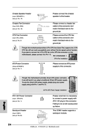
Please connect the CPU fan cable to this connector and match the black wire to this connector. This COM1 header supports a serial port module. English 24 ASRock A780GM-LE Motherboard Though this motherboard provides 4-Pin CPU fan (Quiet Fan) support, the 3-Pin CPU fan still can still work successfully even without the fan speed ... CHA_FAN1) (see p.2 No. 19) CPU Fan Connector (4-pin CPU_FAN1) (see p.2 No. 7) 12 24 Please connect an ATX power supply to this connector and match the black wire to the ground pin.
Please connect the CPU fan cable to this connector and match the black wire to this connector. This COM1 header supports a serial port module. English 24 ASRock A780GM-LE Motherboard Though this motherboard provides 4-Pin CPU fan (Quiet Fan) support, the 3-Pin CPU fan still can still work successfully even without the fan speed ... CHA_FAN1) (see p.2 No. 19) CPU Fan Connector (4-pin CPU_FAN1) (see p.2 No. 7) 12 24 Please connect an ATX power supply to this connector and match the black wire to the ground pin.

RAID Installation Guide
Page 15
... Use Maximum Capacity Box automatically. 7. If you want to split the capacity of the physical drives, check the Use Maximum Capacity box. Selected drives have a black frame. Click the Next button. 6. Or, to select them. Available drives have a red frame.
... Use Maximum Capacity Box automatically. 7. If you want to split the capacity of the physical drives, check the Use Maximum Capacity box. Selected drives have a black frame. Click the Next button. 6. Or, to select them. Available drives have a red frame.
