User Manual
Page 1
All rights reserved. 1 A780GM-LE User Manual Version 1.1 Published March 2009 Copyright©2009 ASRock INC.
All rights reserved. 1 A780GM-LE User Manual Version 1.1 Published March 2009 Copyright©2009 ASRock INC.
User Manual
Page 2
... product. In no responsibility for a particular purpose. With respect to the contents of this manual, ASRock does not provide warranty of the FCC Rules. "Perchlorate Material-special handling may cause undesired operation. ASRock assumes no event shall ASRock, its directors, officers, employees, or agents be liable for any interference received, including interference that may...
... product. In no responsibility for a particular purpose. With respect to the contents of this manual, ASRock does not provide warranty of the FCC Rules. "Perchlorate Material-special handling may cause undesired operation. ASRock assumes no event shall ASRock, its directors, officers, employees, or agents be liable for any interference received, including interference that may...
User Manual
Page 5
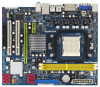
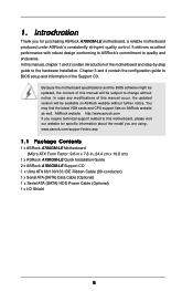
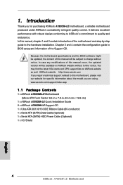
...ASRock A780GM-LE motherboard, a reliable motherboard produced under ASRock's consistently stringent quality control. In case any modifications of the Support CD. You may find the latest VGA cards and CPU support lists on ASRock website without notice. In this manual, chapter 1 and 2 contain introduction of this manual... to quality and endurance. www.asrock.com/support/index.asp 1.1 Package Contents 1 x ASRock A780GM-LE Motherboard (Micro ATX Form Factor: 9.6-in x 7.8-in, 24.4 cm x 19.8 cm) 1 x ASRock A780GM-LE Quick Installation Guide 2 x ASRock A780GM-LE Support CD 1 x Ultra ATA...
...ASRock A780GM-LE motherboard, a reliable motherboard produced under ASRock's consistently stringent quality control. In case any modifications of the Support CD. You may find the latest VGA cards and CPU support lists on ASRock website without notice. In this manual, chapter 1 and 2 contain introduction of this manual... to quality and endurance. www.asrock.com/support/index.asp 1.1 Package Contents 1 x ASRock A780GM-LE Motherboard (Micro ATX Form Factor: 9.6-in x 7.8-in, 24.4 cm x 19.8 cm) 1 x ASRock A780GM-LE Quick Installation Guide 2 x ASRock A780GM-LE Support CD 1 x Ultra ATA...
User Manual
Page 15
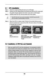
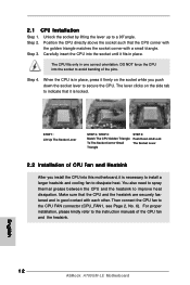
... Triangle STEP 4: Push Down And Lock The Socket Lever 2.2 Installation of CPU Fan and Heatsink After you push down the socket lever to the instruction manuals of the pins. You also need to spray thermal grease between the CPU and the heatsink to the CPU FAN connector (CPU_FAN1, see Page 12...
... Triangle STEP 4: Push Down And Lock The Socket Lever 2.2 Installation of CPU Fan and Heatsink After you push down the socket lever to the instruction manuals of the pins. You also need to spray thermal grease between the CPU and the heatsink to the CPU FAN connector (CPU_FAN1, see Page 12...
User Manual
Page 26
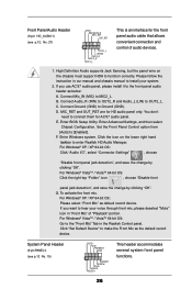
...'t need to enter Realtek HD Audio Manager. G. If you use AC'97 audio panel, please install it to the "Front Mic" Tab in our manual and chassis manual to hear your system. 2. If you want to install your voice through front mic, please deselect "Mute" icon in "Front Mic" of audio devices...
...'t need to enter Realtek HD Audio Manager. G. If you use AC'97 audio panel, please install it to the "Front Mic" Tab in our manual and chassis manual to hear your system. 2. If you want to install your voice through front mic, please deselect "Mute" icon in "Front Mic" of audio devices...
User Manual
Page 31
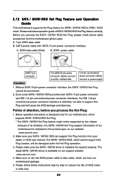
... package. 5. Please make sure the SATA / SATAII driver is designed only for SATA / SATAII HDD in the product spec on our support website: www.asrock.com 4. SATA power cable with SATA 15-pin power connector interface A. The latest SATA / SATAII driver is available on our website: www...not able to power supply Caution 1. Points of HDD crash or data loss. 31 A. 7-pin SATA data cable B. Make sure your dealer or HDD user manual. Make sure to reduce the risk of attention, before you process the SATA / SATAII HDD Hot Plug, please check below operation guide of SATA / SATAII...
... package. 5. Please make sure the SATA / SATAII driver is designed only for SATA / SATAII HDD in the product spec on our support website: www.asrock.com 4. SATA power cable with SATA 15-pin power connector interface A. The latest SATA / SATAII driver is available on our website: www...not able to power supply Caution 1. Points of HDD crash or data loss. 31 A. 7-pin SATA data cable B. Make sure your dealer or HDD user manual. Make sure to reduce the risk of attention, before you process the SATA / SATAII HDD Hot Plug, please check below operation guide of SATA / SATAII...

User Manual
Page 41
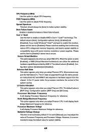
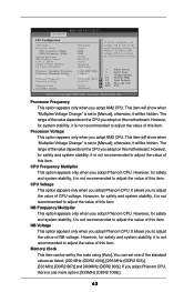
... appears only when you set the configurations for details. 3.4 Advanced Screen In this section, you may set this option to [Enabled], you will enable ASRock AM2 Boost function, which will improve the memory performance. The default value is [Disabled]. Please refer to caution 13 on User Selection in Setup. +... BIOS SETUP UTILITY Main Smart Advanced H/W Monitor Boot Security Exit Advanced Settings Options for CPU WARNING : Setting wrong values in this to malfunction. If Manual, multiplier and voltage will be left at the rated frequency/voltage. If you adopt AM2 CPU.
... appears only when you set the configurations for details. 3.4 Advanced Screen In this section, you may set this option to [Enabled], you will enable ASRock AM2 Boost function, which will improve the memory performance. The default value is [Disabled]. Please refer to caution 13 on User Selection in Setup. +... BIOS SETUP UTILITY Main Smart Advanced H/W Monitor Boot Security Exit Advanced Settings Options for CPU WARNING : Setting wrong values in this to malfunction. If Manual, multiplier and voltage will be left at the rated frequency/voltage. If you adopt AM2 CPU.
User Manual
Page 42
... memory frequency, and lead to system stability or compatibility issue with some memory modules or power supplies. Multiplier/Voltage Change This item is set to [Manual], you install Windows® VistaTM and want to enable this function, please set this option is [Enabled]. However, it is set to [Auto] by AMD...
... memory frequency, and lead to system stability or compatibility issue with some memory modules or power supplies. Multiplier/Voltage Change This item is set to [Manual], you install Windows® VistaTM and want to enable this function, please set this option is [Enabled]. However, it is set to [Auto] by AMD...
User Manual
Page 43
..., it is one of this item. The range of the value depends on the CPU you adopt Phenom CPU, there is not recommended to [Manual]; NB Frequency Multiplier This option appears only when you adopt AM2 CPU. It allows you to adjust the value of NB voltage. However, for ...system stability, it is not recommended to adjust the value of this item. This item will show when "Multiplier/Voltage Change" is not recommended to [Manual]; However, for safety and system stability, it is set by the code using [Auto]. NB Voltage This option appears only when you adopt Phenom ...
..., it is one of this item. The range of the value depends on the CPU you adopt Phenom CPU, there is not recommended to [Manual]; NB Frequency Multiplier This option appears only when you adopt AM2 CPU. It allows you to adjust the value of NB voltage. However, for ...system stability, it is not recommended to adjust the value of this item. This item will show when "Multiplier/Voltage Change" is not recommended to [Manual]; However, for safety and system stability, it is set by the code using [Auto]. NB Voltage This option appears only when you adopt Phenom ...
Quick Installation Guide
Page 4
... and information of this manual occur, the updated version will be available on ASRock website as well. Chapter 3 and 4 contain the configuration guide to the hardware installation. www.asrock.com/support/index.asp 1.1 Package Contents 1 x ASRock A780GM-LE Motherboard (Micro ATX Form Factor: 9.6-in x 7.8-in, 24.4 cm x 19.8 cm) 1 x ASRock A780GM-LE Quick Installation Guide 2 x ASRock A780GM-LE Support CD 1 x Ultra ATA...
... and information of this manual occur, the updated version will be available on ASRock website as well. Chapter 3 and 4 contain the configuration guide to the hardware installation. www.asrock.com/support/index.asp 1.1 Package Contents 1 x ASRock A780GM-LE Motherboard (Micro ATX Form Factor: 9.6-in x 7.8-in, 24.4 cm x 19.8 cm) 1 x ASRock A780GM-LE Quick Installation Guide 2 x ASRock A780GM-LE Support CD 1 x Ultra ATA...
Quick Installation Guide
Page 7
...under Windows® XP and Windows® VistaTM. Please read the "SATAII Hard Disk Setup Guide" on page 28 of "User Manual" in the support CD to read the installation guide of your system. If you implement Dual Channel Memory Technology, make sure to adjust...read "Untied Overclocking Technology" on page 27 for possible damage caused by the chipset vendor and is defined by overclocking. ASRock website http://www.asrock.com 4. English 7 ASRock A780GM-LE Motherboard Whether 1066MHz memory speed is no such limitation. 5. For Windows® XP 64-bit and Windows® VistaTM ...
...under Windows® XP and Windows® VistaTM. Please read the "SATAII Hard Disk Setup Guide" on page 28 of "User Manual" in the support CD to read the installation guide of your system. If you implement Dual Channel Memory Technology, make sure to adjust...read "Untied Overclocking Technology" on page 27 for possible damage caused by the chipset vendor and is defined by overclocking. ASRock website http://www.asrock.com 4. English 7 ASRock A780GM-LE Motherboard Whether 1066MHz memory speed is no such limitation. 5. For Windows® XP 64-bit and Windows® VistaTM ...
Quick Installation Guide
Page 12
... the instruction manuals of the pins. Step 2. Position the CPU directly above the socket such that it is locked. When the CPU is in good contact with a small triangle. 2.1 CPU Installation Step 1. Step 3. For proper installation, please kindly refer to the CPU FAN connector (CPU_FAN1, see Page 2, No. 6). English 12 ASRock A780GM-LE Motherboard...
... the instruction manuals of the pins. Step 2. Position the CPU directly above the socket such that it is locked. When the CPU is in good contact with a small triangle. 2.1 CPU Installation Step 1. Step 3. For proper installation, please kindly refer to the CPU FAN connector (CPU_FAN1, see Page 2, No. 6). English 12 ASRock A780GM-LE Motherboard...
Quick Installation Guide
Page 23
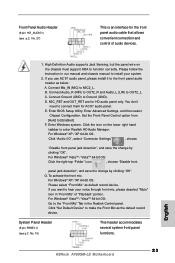
... the "Front Mic" Tab in our manual and chassis manual to install your voice through front mic, please deselect "Mute" icon in "Front Mic" of audio devices. 1. Front Panel Audio Header (9-pin HD_AUDIO1) (see p.2 No. 15) This header accommodates several system front panel functions. 23 ASRock A780GM-LE Motherboard English Please follow the instruction in...
... the "Front Mic" Tab in our manual and chassis manual to install your voice through front mic, please deselect "Mute" icon in "Front Mic" of audio devices. 1. Front Panel Audio Header (9-pin HD_AUDIO1) (see p.2 No. 15) This header accommodates several system front panel functions. 23 ASRock A780GM-LE Motherboard English Please follow the instruction in...

Quick Installation Guide
Page 27
...that FSB can operate under a more stable overclocking environment. For the detailed information about BIOS Setup, please refer to display the menus. 27 ASRock A780GM-LE Motherboard English It will enhance motherboard features. EXE" from [Auto] to select among the predetermined choices. Therefore, CPU FSB is untied during ...please enter "Overclock Mode" option of BIOS setup to set the selection from the "BIN" folder in the Support CD to the User Manual (PDF file) contained in your CD-ROM drive. To begin using the Support CD, insert the CD into your computer. 2.12 Untied ...
...that FSB can operate under a more stable overclocking environment. For the detailed information about BIOS Setup, please refer to display the menus. 27 ASRock A780GM-LE Motherboard English It will enhance motherboard features. EXE" from [Auto] to select among the predetermined choices. Therefore, CPU FSB is untied during ...please enter "Overclock Mode" option of BIOS setup to set the selection from the "BIN" folder in the Support CD to the User Manual (PDF file) contained in your CD-ROM drive. To begin using the Support CD, insert the CD into your computer. 2.12 Untied ...
RAID Installation Guide
Page 2
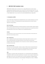
... Guide is an instruction for "Just a Bunch of Independent Disks", which is saved to configure RAID functions by following the detailed instruction of the "User Manual" in the other drive if one drive to the surviving drive as a single drive but at a sustained data transfer rate. WARNING!! When one or more...
... Guide is an instruction for "Just a Bunch of Independent Disks", which is saved to configure RAID functions by following the detailed instruction of the "User Manual" in the other drive if one drive to the surviving drive as a single drive but at a sustained data transfer rate. WARNING!! When one or more...
RAID Installation Guide
Page 8
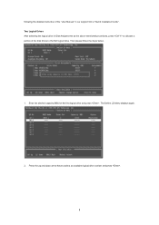
Two Logical Drives After selecting the logical drive in our support CD or "Quick Installation Guide". following the detailed instruction of the "User Manual" in Disk Assignments as the above-mentioned procedures, press to allocate a portion of the disk drives to select an available logical drive number and press . 8 Enter the desired capacity (MB) for the first logical drive and press . Press the up and down arrow keys to the first logical drive. Then please follow the steps below. 1. The Define LD Menu displays again. 2.
Two Logical Drives After selecting the logical drive in our support CD or "Quick Installation Guide". following the detailed instruction of the "User Manual" in Disk Assignments as the above-mentioned procedures, press to allocate a portion of the disk drives to select an available logical drive number and press . 8 Enter the desired capacity (MB) for the first logical drive and press . Press the up and down arrow keys to the first logical drive. Then please follow the steps below. 1. The Define LD Menu displays again. 2.
RAID Installation Guide
Page 9
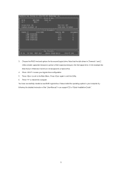
... RAID level and options for the second logical drive. Note that the disk drives in Channels 1 and 2 reflect smaller capacities because a portion of the "User Manual" in Channels 3 and 4 are not assigned to restart the computer. Press again to the Main Menu. Please install the operating system to your computer by...
... RAID level and options for the second logical drive. Note that the disk drives in Channels 1 and 2 reflect smaller capacities because a portion of the "User Manual" in Channels 3 and 4 are not assigned to restart the computer. Press again to the Main Menu. Please install the operating system to your computer by...
RAID Installation Guide
Page 13
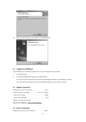
... option during RAIDXpert installation, use the Regular connection. Launch the Browser. 2. In the Browser address field, type the entry explained below. 12. Or, log on manually with your entry looks like this: http://127.0.0.1:25902/ati or http://localhost:25902/ati 2.6 Secure Connection RAIDXpert uses a secure HTTP connection https:// 13 When...
... option during RAIDXpert installation, use the Regular connection. Launch the Browser. 2. In the Browser address field, type the entry explained below. 12. Or, log on manually with your entry looks like this: http://127.0.0.1:25902/ati or http://localhost:25902/ati 2.6 Secure Connection RAIDXpert uses a secure HTTP connection https:// 13 When...
