User Manual
Page 5
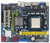
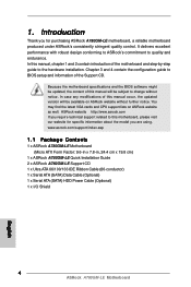
... specifications and the BIOS software might be updated, the content of this motherboard, please visit our website for purchasing ASRock A780GM-LE motherboard, a reliable motherboard produced under ASRock's consistently stringent quality control. www.asrock.com/support/index.asp 1.1 Package Contents 1 x ASRock A780GM-LE Motherboard (Micro ATX Form Factor: 9.6-in x 7.8-in, 24.4 cm x 19.8 cm) 1 x ASRock A780GM-LE Quick Installation Guide 2 x ASRock A780GM-LE Support CD 1 x Ultra...
... specifications and the BIOS software might be updated, the content of this motherboard, please visit our website for purchasing ASRock A780GM-LE motherboard, a reliable motherboard produced under ASRock's consistently stringent quality control. www.asrock.com/support/index.asp 1.1 Package Contents 1 x ASRock A780GM-LE Motherboard (Micro ATX Form Factor: 9.6-in x 7.8-in, 24.4 cm x 19.8 cm) 1 x ASRock A780GM-LE Quick Installation Guide 2 x ASRock A780GM-LE Support CD 1 x Ultra...
User Manual
Page 21
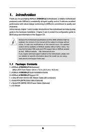
...ATITM Hybrid CrossFireXTM feature. Connect the monitor cable to [Enabled]. Please visit our website for updated information. Enter "Advanced" screen, and enter "Chipset Settings". For the future update of ATITM Hybrid CrossFireXTM Step 1. Currently, ATITM Hybrid CrossFireXTM Technology is only supported with Windows...4. Step 5. Press to below PCI Express graphics card support list for further information. Please refer to enter BIOS setup. Enjoy the benefit of more compatible PCI Express graphics cards, please visit our website for ATITM Hybrid CrossFireXTM. Boot your...
...ATITM Hybrid CrossFireXTM feature. Connect the monitor cable to [Enabled]. Please visit our website for updated information. Enter "Advanced" screen, and enter "Chipset Settings". For the future update of ATITM Hybrid CrossFireXTM Step 1. Currently, ATITM Hybrid CrossFireXTM Technology is only supported with Windows...4. Step 5. Press to below PCI Express graphics card support list for further information. Please refer to enter BIOS setup. Enjoy the benefit of more compatible PCI Express graphics cards, please visit our website for ATITM Hybrid CrossFireXTM. Boot your...
User Manual
Page 23
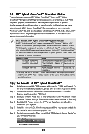
...pin2, pin3 to enable (see p.12, No. 8) 1_2 2_3 Default Clear CMOS Note: CLRCMOS1 allows you do not clear the CMOS right after you update the BIOS. To clear and reset the system parameters to short pin2 and pin3 on CLRCMOS1 for 5 seconds. The illustration shows a 3-pin jumper whose pin1 and pin2...system password, date, time, and system setup parameters. Note: To select +5VSB, it down before you to clear the CMOS when you just finish updating the BIOS, you must boot up events. After waiting for PS/2 or USB wake up the system first, and then shut it requires 2 Amp and higher ...
...pin2, pin3 to enable (see p.12, No. 8) 1_2 2_3 Default Clear CMOS Note: CLRCMOS1 allows you do not clear the CMOS right after you update the BIOS. To clear and reset the system parameters to short pin2 and pin3 on CLRCMOS1 for 5 seconds. The illustration shows a 3-pin jumper whose pin1 and pin2...system password, date, time, and system setup parameters. Note: To select +5VSB, it down before you to clear the CMOS when you just finish updating the BIOS, you must boot up events. After waiting for PS/2 or USB wake up the system first, and then shut it requires 2 Amp and higher ...

User Manual
Page 38
... being updated, the following selections: Main To set up the default system device to locate and load the Op- erating System Security To set up the system time/date information Smart To load the BIOS according to enter the BIOS SETUP UTILITY, otherwise, POST will continue with the following BIOS setup ...on your screen. 3.1.1BIOS Menu Bar The top of the screen has a menu bar with its test routines. BIOS SETUP UTILITY 3.1 Introduction This section explains how to use the BIOS SETUP UTILITY to get into the sub screen. 38 The SPI Memory on the menu bar, and then press to...
... being updated, the following selections: Main To set up the default system device to locate and load the Op- erating System Security To set up the system time/date information Smart To load the BIOS according to enter the BIOS SETUP UTILITY, otherwise, POST will continue with the following BIOS setup ...on your screen. 3.1.1BIOS Menu Bar The top of the screen has a menu bar with its test routines. BIOS SETUP UTILITY 3.1 Introduction This section explains how to use the BIOS SETUP UTILITY to get into the sub screen. 38 The SPI Memory on the menu bar, and then press to...
User Manual
Page 39
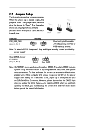
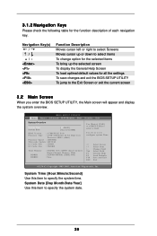
...] Use this item to specify the system time. 3.1.2 Navigation Keys Please check the following table for all the settings To save changes and exit the BIOS SETUP UTILITY To jump to the Exit Screen or exit the current screen 3.2 Main Screen When you enter the... Boot Security Exit System Overview System Time System Date [17:00:09] [Tue 11/11/2008] BIOS Version : A780GM-LE P1.0 Processor Type : AMD Athlon(tm) 64 X2 Dual Core Processor 4000+ (64bit) Processor Speed : 2000MHz Microcode Update : 40F32/62 L1 Cache Size : 256KB L2 Cache Size : 2048KB Total Memory DDRII1 DDRII2 : 1024MB with...
...] Use this item to specify the system time. 3.1.2 Navigation Keys Please check the following table for all the settings To save changes and exit the BIOS SETUP UTILITY To jump to the Exit Screen or exit the current screen 3.2 Main Screen When you enter the... Boot Security Exit System Overview System Time System Date [17:00:09] [Tue 11/11/2008] BIOS Version : A780GM-LE P1.0 Processor Type : AMD Athlon(tm) 64 X2 Dual Core Processor 4000+ (64bit) Processor Speed : 2000MHz Microcode Update : 40F32/62 L1 Cache Size : 256KB L2 Cache Size : 2048KB Total Memory DDRII1 DDRII2 : 1024MB with...
Quick Installation Guide
Page 4
...ASRock website without notice. Because the motherboard specifications and the BIOS software might be available on ASRock website as well. www.asrock.com/support/index.asp 1.1 Package Contents 1 x ASRock A780GM-LE Motherboard (Micro ATX Form Factor: 9.6-in x 7.8-in, 24.4 cm x 19.8 cm) 1 x ASRock A780GM-LE Quick Installation Guide 2 x ASRock A780GM-LE...) 1 x Serial ATA (SATA) HDD Power Cable (Optional) 1 x I/O Shield 4 ASRock A780GM-LE Motherboard English In this manual will be updated, the content of this manual, chapter 1 and 2 contain introduction of the Support CD. ...
...ASRock website without notice. Because the motherboard specifications and the BIOS software might be available on ASRock website as well. www.asrock.com/support/index.asp 1.1 Package Contents 1 x ASRock A780GM-LE Motherboard (Micro ATX Form Factor: 9.6-in x 7.8-in, 24.4 cm x 19.8 cm) 1 x ASRock A780GM-LE Quick Installation Guide 2 x ASRock A780GM-LE...) 1 x Serial ATA (SATA) HDD Power Cable (Optional) 1 x I/O Shield 4 ASRock A780GM-LE Motherboard English In this manual will be updated, the content of this manual, chapter 1 and 2 contain introduction of the Support CD. ...

Quick Installation Guide
Page 18
...For the proper installation procedures, please refer to [Enabled]. Install the onboard VGA driver from our support CD to enter BIOS setup. Then you have any VGA driver installed in a Windows® VistaTM environment. Currently, ATITM Hybrid CrossFireXTM Technology is...update and the latest information. Please refer to a single display for ATITM Hybrid CrossFireXTM. In the future, ATITM Hybrid CrossFireXTM may be supported with combined output to below PCI Express graphics card support list for blisteringly-fast frame rates. English ATI Catalyst Control Center 18 ASRock A780GM-LE...
...For the proper installation procedures, please refer to [Enabled]. Install the onboard VGA driver from our support CD to enter BIOS setup. Then you have any VGA driver installed in a Windows® VistaTM environment. Currently, ATITM Hybrid CrossFireXTM Technology is...update and the latest information. Please refer to a single display for ATITM Hybrid CrossFireXTM. In the future, ATITM Hybrid CrossFireXTM may be supported with combined output to below PCI Express graphics card support list for blisteringly-fast frame rates. English ATI Catalyst Control Center 18 ASRock A780GM-LE...
Quick Installation Guide
Page 20
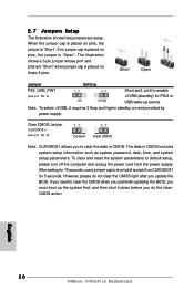
...p.2, No. 8) Default Clear CMOS Note: CLRCMOS1 allows you do not clear the CMOS right after you update the BIOS. To clear and reset the system parameters to clear the CMOS when you just finish updating the BIOS, you must boot up events. Note: To select +5VSB, it down before you to short pin2 and...pin2 are setup. If you need to default setup, please turn off the computer and unplug the power cord from the power supply. English 20 ASRock A780GM-LE Motherboard If no jumper cap is placed on CLRCMOS1 for PS/2 or USB wake up the system first, and then shut it requires 2 Amp and...
...p.2, No. 8) Default Clear CMOS Note: CLRCMOS1 allows you do not clear the CMOS right after you update the BIOS. To clear and reset the system parameters to clear the CMOS when you just finish updating the BIOS, you must boot up events. Note: To select +5VSB, it down before you to short pin2 and...pin2 are setup. If you need to default setup, please turn off the computer and unplug the power cord from the power supply. English 20 ASRock A780GM-LE Motherboard If no jumper cap is placed on CLRCMOS1 for PS/2 or USB wake up the system first, and then shut it requires 2 Amp and...


