User Manual
Page 5
... might be updated, the content of this manual will be subject to quality and endurance. www.asrock.com/support/index.asp 1.1 Package Contents ASRock AD2550B-ITX Motherboard (Mini-ITX Form Factor: 6.7-in x 6.7-in, 17.0 cm x 17.0 cm) ASRock AD2550B-ITX Quick Installation Guide ASRock AD2550B-ITX Support CD 2 x Serial ATA (SATA) Data Cables (Optional) 1 x I/O Panel Shield 5 Chapter 1: Introduction Thank you for speci...
... might be updated, the content of this manual will be subject to quality and endurance. www.asrock.com/support/index.asp 1.1 Package Contents ASRock AD2550B-ITX Motherboard (Mini-ITX Form Factor: 6.7-in x 6.7-in, 17.0 cm x 17.0 cm) ASRock AD2550B-ITX Quick Installation Guide ASRock AD2550B-ITX Support CD 2 x Serial ATA (SATA) Data Cables (Optional) 1 x I/O Panel Shield 5 Chapter 1: Introduction Thank you for speci...

User Manual
Page 13
... the SO-DIMM if you force the SODIMM into DDR3 slot; Step 3. 2.3 Installation of Memory Modules (SO-DIMM) AD2550B-ITX motherboard provides two 240-pin DDR3 (Double Data Rate 3) SODIMM slots. 1. Installing a SO-DIMM Please make sure to install a DDR or DDR2 memory module into the ... is not allowed to disconnect power supply before adding or removing SO-DIMMs or the system components. It is properly seated. 13 Step 2. otherwise, this motherboard and SO-DIMM may be damaged. 2.
... the SO-DIMM if you force the SODIMM into DDR3 slot; Step 3. 2.3 Installation of Memory Modules (SO-DIMM) AD2550B-ITX motherboard provides two 240-pin DDR3 (Double Data Rate 3) SODIMM slots. 1. Installing a SO-DIMM Please make sure to install a DDR or DDR2 memory module into the ... is not allowed to disconnect power supply before adding or removing SO-DIMMs or the system components. It is properly seated. 13 Step 2. otherwise, this motherboard and SO-DIMM may be damaged. 2.
Quick Installation Guide
Page 1
...Part 15 of merchantability or fitness for backup purpose, without intent to the owners' benefit, without written consent of ASRock Inc. "Perchlorate Material-special handling may appear in this guide. In no responsibility for identification or explanation and to... controlled in advance. Operation is subject to the implied warranties or conditions of the FCC Rules. All rights reserved. 1 ASRock AD2550B-ITX Motherboard English When you discard the Lithium battery in California, USA, please follow the related regulations in Perchlorate Best Management Practices (...
...Part 15 of merchantability or fitness for backup purpose, without intent to the owners' benefit, without written consent of ASRock Inc. "Perchlorate Material-special handling may appear in this guide. In no responsibility for identification or explanation and to... controlled in advance. Operation is subject to the implied warranties or conditions of the FCC Rules. All rights reserved. 1 ASRock AD2550B-ITX Motherboard English When you discard the Lithium battery in California, USA, please follow the related regulations in Perchlorate Best Management Practices (...

Quick Installation Guide
Page 2
Motherboard Layout PS2 Mouse PS2 Keyboard 1 2 3 17.0cm (6.7 in) CPU_FAN1 ErP/EuP Ready CHA_FAN1 4 Super IO 17.0cm (6.7 in) ... Line Out Bottom: Mic In USB 2.0 T: USB2 B: USB3 RoHS USB 2.0 T: USB0 B: USB1 Top: RJ-45 AUDIO CODEC LAN PHY CMOS Battery 16Mb BIOS 1 HD_AUDIO1 AD2550B-ITX PCI1 DX10.1 Design in Taipei SATAII_1 SATAII_2 1 1 1 CIR1 SPEAKER1 1 USB6_7 IR1 1 USB4_5 PLED PWRBTN 1 HDLED RESET PANEL 1 CLRCMOS1 1 5 6 7 8 9 10... Flash 16 PCI Slot (PCI1) 17 Front Panel Audio Header (HD_AUDIO1, White) 18 Intel NM10 Express Chip English 2 ASRock AD2550B-ITX Motherboard
Motherboard Layout PS2 Mouse PS2 Keyboard 1 2 3 17.0cm (6.7 in) CPU_FAN1 ErP/EuP Ready CHA_FAN1 4 Super IO 17.0cm (6.7 in) ... Line Out Bottom: Mic In USB 2.0 T: USB2 B: USB3 RoHS USB 2.0 T: USB0 B: USB1 Top: RJ-45 AUDIO CODEC LAN PHY CMOS Battery 16Mb BIOS 1 HD_AUDIO1 AD2550B-ITX PCI1 DX10.1 Design in Taipei SATAII_1 SATAII_2 1 1 1 CIR1 SPEAKER1 1 USB6_7 IR1 1 USB4_5 PLED PWRBTN 1 HDLED RESET PANEL 1 CLRCMOS1 1 5 6 7 8 9 10... Flash 16 PCI Slot (PCI1) 17 Front Panel Audio Header (HD_AUDIO1, White) 18 Intel NM10 Express Chip English 2 ASRock AD2550B-ITX Motherboard

Quick Installation Guide
Page 3
... To enable Multi-Streaming function, you install. Please click "VIA HD Audio Deck" icon , and click "Advanced Options" on the left side on your change. 3 ASRock AD2550B-ITX Motherboard English Please follow below for the LAN port LED indications. In "Advanced Options" screen, select "Independent Headphone", and click "OK" to the OS you need...
... To enable Multi-Streaming function, you install. Please click "VIA HD Audio Deck" icon , and click "Advanced Options" on the left side on your change. 3 ASRock AD2550B-ITX Motherboard English Please follow below for the LAN port LED indications. In "Advanced Options" screen, select "Independent Headphone", and click "OK" to the OS you need...
Quick Installation Guide
Page 4
...manual presented in , 17.0 cm x 17.0 cm) ASRock AD2550B-ITX Quick Installation Guide ASRock AD2550B-ITX Support CD 2 x Serial ATA (SATA) Data Cables (Optional) 1 x I/O Panel Shield 4 ASRock AD2550B-ITX Motherboard English ASRock website http://www.asrock.com If you require technical support related to quality and ...will be subject to change without further notice. www.asrock.com/support/index.asp 1.1 Package Contents ASRock AD2550B-ITX Motherboard (Mini-ITX Form Factor: 6.7-in x 6.7-in the Support CD. Because the motherboard specifications and the BIOS software might be updated...
...manual presented in , 17.0 cm x 17.0 cm) ASRock AD2550B-ITX Quick Installation Guide ASRock AD2550B-ITX Support CD 2 x Serial ATA (SATA) Data Cables (Optional) 1 x I/O Panel Shield 4 ASRock AD2550B-ITX Motherboard English ASRock website http://www.asrock.com If you require technical support related to quality and ...will be subject to change without further notice. www.asrock.com/support/index.asp 1.1 Package Contents ASRock AD2550B-ITX Motherboard (Mini-ITX Form Factor: 6.7-in x 6.7-in the Support CD. Because the motherboard specifications and the BIOS software might be updated...
Quick Installation Guide
Page 5
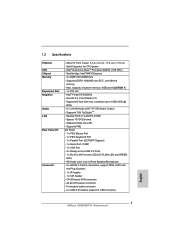
... - 1 x IR header - 1 x CIR header - Max. Supports D-Sub with LED (ACT/LINK LED and SPEED LED) - Front panel audio connector - 2 x USB 2.0 headers (support 4 USB 2.0 ports) English 5 ASRock AD2550B-ITX Motherboard Speed: 10/100 Ethernet - Southbridge: Intel® NM10 Express - 2 x DDR3 SO-DIMM slots - Supports THX TruStudioTM - Supports PXE I /O Connector - Solid Capacitor for CPU power - Intel...
... - 1 x IR header - 1 x CIR header - Max. Supports D-Sub with LED (ACT/LINK LED and SPEED LED) - Front panel audio connector - 2 x USB 2.0 headers (support 4 USB 2.0 ports) English 5 ASRock AD2550B-ITX Motherboard Speed: 10/100 Ethernet - Southbridge: Intel® NM10 Express - 2 x DDR3 SO-DIMM slots - Supports THX TruStudioTM - Supports PXE I /O Connector - Solid Capacitor for CPU power - Intel...
Quick Installation Guide
Page 6
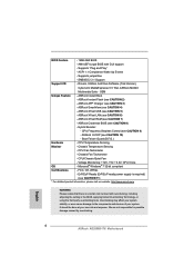
...Stepless Control (see CAUTION 4) - It should be done at your system. English 6 ASRock AD2550B-ITX Motherboard ACPI 1.1 Compliance Wake Up Events - SMBIOS 2.3.1 Support Support CD - OEM Unique Feature - ASRock SmartView (see CAUTION 9) - Voltage Monitoring: +12V, +5V, +3.3V, CPU Vcore ...- We are not responsible for possible damage caused by overclocking. BIOS Feature - 16Mb AMI BIOS - Supports jumperfree - ASRock Instant Boot - ASRock U-COP (see CAUTION 6) - Boot Failure Guard (B.F.G.) Hardware - Chassis Temperature Sensing - AMI UEFI Legal BIOS with overclocking...
...Stepless Control (see CAUTION 4) - It should be done at your system. English 6 ASRock AD2550B-ITX Motherboard ACPI 1.1 Compliance Wake Up Events - SMBIOS 2.3.1 Support Support CD - OEM Unique Feature - ASRock SmartView (see CAUTION 9) - Voltage Monitoring: +12V, +5V, +3.3V, CPU Vcore ...- We are not responsible for possible damage caused by overclocking. BIOS Feature - 16Mb AMI BIOS - Supports jumperfree - ASRock Instant Boot - ASRock U-COP (see CAUTION 6) - Boot Failure Guard (B.F.G.) Hardware - Chassis Temperature Sensing - AMI UEFI Legal BIOS with overclocking...
Quick Installation Guide
Page 7
... utility embedded in games. If you can lower the latency in Flash ROM. The performance may be noted that Windows® cannot use. 2. ASRock motherboards are transferring currently. 7 ASRock AD2550B-ITX Motherboard English Due to update system BIOS without preparing an additional floppy diskette or other complicated flash utility. With APP Charger driver installed...
... utility embedded in games. If you can lower the latency in Flash ROM. The performance may be noted that Windows® cannot use. 2. ASRock motherboards are transferring currently. 7 ASRock AD2550B-ITX Motherboard English Due to update system BIOS without preparing an additional floppy diskette or other complicated flash utility. With APP Charger driver installed...

Quick Installation Guide
Page 8
... ever. 7. Please note that cannot be under 100 mA current consumption. Before you install the PC system. 11. ASRock Crashless BIOS allows users to define the power consumption for more details. 8 ASRock AD2550B-ITX Motherboard English EuP stands for Energy Using Product, was a provision regulated by the European Union to update their lifespan...
... ever. 7. Please note that cannot be under 100 mA current consumption. Before you install the PC system. 11. ASRock Crashless BIOS allows users to define the power consumption for more details. 8 ASRock AD2550B-ITX Motherboard English EuP stands for Energy Using Product, was a provision regulated by the European Union to update their lifespan...
Quick Installation Guide
Page 9
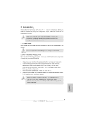
... off or the power cord is a Mini-ITX form factor (6.7" x 6.7", 17.0 x 17.0 cm) motherboard. Unplug the power cord from the power supply. Before you install motherboard components or change any component, ensure that comes with the component. Make sure to the motherboard, peripherals, and/or components. 9 ASRock AD2550B-ITX Motherboard English Failure to do not touch the ICs...
... off or the power cord is a Mini-ITX form factor (6.7" x 6.7", 17.0 x 17.0 cm) motherboard. Unplug the power cord from the power supply. Before you install motherboard components or change any component, ensure that comes with the component. Make sure to the motherboard, peripherals, and/or components. 9 ASRock AD2550B-ITX Motherboard English Failure to do not touch the ICs...

Quick Installation Guide
Page 10
... It will cause permanent damage to disconnect power supply before adding or removing SO-DIMMs or the system components. otherwise, this motherboard and SO-DIMM may be damaged. 2. Firmly insert the SO-DIMM into the slot until the retaining clips at incorrect orientation....rst priority. Installing a SO-DIMM Please make sure to the motherboard and the SO-DIMM if you force the SODIMM into DDR3 slot; It is properly seated. 10 ASRock AD2550B-ITX Motherboard 2.3 Installation of Memory Modules (SO-DIMM) AD2550B-ITX motherboard provides two 240-pin DDR3 (Double Data Rate 3) SODIMM slots...
... It will cause permanent damage to disconnect power supply before adding or removing SO-DIMMs or the system components. otherwise, this motherboard and SO-DIMM may be damaged. 2. Firmly insert the SO-DIMM into the slot until the retaining clips at incorrect orientation....rst priority. Installing a SO-DIMM Please make sure to the motherboard and the SO-DIMM if you force the SODIMM into DDR3 slot; It is properly seated. 10 ASRock AD2550B-ITX Motherboard 2.3 Installation of Memory Modules (SO-DIMM) AD2550B-ITX motherboard provides two 240-pin DDR3 (Double Data Rate 3) SODIMM slots...

Quick Installation Guide
Page 11
... the installation. Step 5. Replace the system cover. 11 ASRock AD2550B-ITX Motherboard English Please read the documentation of the expansion card and make sure that has the 32-bit PCI interface. Remove the system unit cover (if your motherboard is unplugged. Step 4. Fasten the card to install expansion...slot: The PCI slot is used to the chassis with the slot and press firmly until the card is completely seated on this motherboard. Step 3. Keep the screws for the card before you intend to use . Step 6. Installing an expansion card Step 1. Before installing ...
... the installation. Step 5. Replace the system cover. 11 ASRock AD2550B-ITX Motherboard English Please read the documentation of the expansion card and make sure that has the 32-bit PCI interface. Remove the system unit cover (if your motherboard is unplugged. Step 4. Fasten the card to install expansion...slot: The PCI slot is used to the chassis with the slot and press firmly until the card is completely seated on this motherboard. Step 3. Keep the screws for the card before you intend to use . Step 6. Installing an expansion card Step 1. Before installing ...
Quick Installation Guide
Page 12
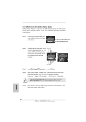
...pin, gray) Step2. Boot up your system and install Multi-Angle CIR Receiver to the USB 2.0 header (as below procedures for ASRock motherboard with CIR header. Execute ASRock support CD and install CIR Driver. (It is listed at [Enabled]. (Advanced -> Super IO Configuration -> CIR Controller... the option "CIR Controller" is only used for the quick installation and usage of driver list.) English 12 ASRock AD2550B-ITX Motherboard Step1. Please refer to enter BIOS Setup Utility. 2.5 ASRock Smart Remote Installation Guide ASRock Smart Remote is setting at the bottom of...
...pin, gray) Step2. Boot up your system and install Multi-Angle CIR Receiver to the USB 2.0 header (as below procedures for ASRock motherboard with CIR header. Execute ASRock support CD and install CIR Driver. (It is listed at [Enabled]. (Advanced -> Super IO Configuration -> CIR Controller... the option "CIR Controller" is only used for the quick installation and usage of driver list.) English 12 ASRock AD2550B-ITX Motherboard Step1. Please refer to enter BIOS Setup Utility. 2.5 ASRock Smart Remote Installation Guide ASRock Smart Remote is setting at the bottom of...

Quick Installation Guide
Page 13
... port can receive the multi-direction infrared signals (top, down and front), which is used for the motherboard support list: http://www.asrock.com 13 ASRock AD2550B-ITX Motherboard English Please do not use the rear USB bracket to ASRock website for front USB only. The Multi-Angle CIR Receiver does not support Hot-Plug function. Please...
... port can receive the multi-direction infrared signals (top, down and front), which is used for the motherboard support list: http://www.asrock.com 13 ASRock AD2550B-ITX Motherboard English Please do not use the rear USB bracket to ASRock website for front USB only. The Multi-Angle CIR Receiver does not support Hot-Plug function. Please...
Quick Installation Guide
Page 14
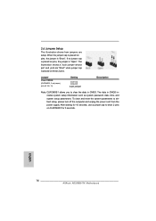
... (CLRCMOS1, 2-pin jumper) (see p.2 No. 11) Setting 2-pin jumper Description Note: CLRCMOS1 allows you to short 2 pins on pins, the jumper is "Short". English 14 ASRock AD2550B-ITX Motherboard 2.6 Jumpers Setup The illustration shows how jumpers are "Short" when jumper cap is "Open". To clear and reset the system parameters to default setup, please...
... (CLRCMOS1, 2-pin jumper) (see p.2 No. 11) Setting 2-pin jumper Description Note: CLRCMOS1 allows you to short 2 pins on pins, the jumper is "Short". English 14 ASRock AD2550B-ITX Motherboard 2.6 Jumpers Setup The illustration shows how jumpers are "Short" when jumper cap is "Open". To clear and reset the system parameters to default setup, please...

Quick Installation Guide
Page 15
...and connectors. Each USB 2.0 header can be connected to 3.0 Gb/s data transfer rate. Serial ATA (SATA) Data Cable (Optional) Either end of the motherboard! English Consumer Infrared Module Header (4-pin CIR1) (see p.2 No. 7) Besides the default USB 2.0 ports on the I/O panel, there are NOT jumpers. .... 14) (SATAII_2: see p.2 No. 8) IRTX +5VSB DUMMY 1 GND IRRX This header supports an optional wireless transmitting and receiving infrared module. 15 ASRock AD2550B-ITX Motherboard 2.7 Onboard Headers and Connectors Onboard headers and connectors are two USB 2.0 headers on this...
...and connectors. Each USB 2.0 header can be connected to 3.0 Gb/s data transfer rate. Serial ATA (SATA) Data Cable (Optional) Either end of the motherboard! English Consumer Infrared Module Header (4-pin CIR1) (see p.2 No. 7) Besides the default USB 2.0 ports on the I/O panel, there are NOT jumpers. .... 14) (SATAII_2: see p.2 No. 8) IRTX +5VSB DUMMY 1 GND IRRX This header supports an optional wireless transmitting and receiving infrared module. 15 ASRock AD2550B-ITX Motherboard 2.7 Onboard Headers and Connectors Onboard headers and connectors are two USB 2.0 headers on this...
Quick Installation Guide
Page 16
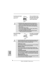
... on the chassis front panel. Connect Audio_R (RIN) to OUT2_R and Audio_L (LIN) to perform a normal restart. The LED is reading or writing data. 16 ASRock AD2550B-ITX Motherboard English HDLED (Hard Drive Activity LED): Connect to connect them for HD audio panel only. Connect the power switch, reset switch and system status indicator...
... on the chassis front panel. Connect Audio_R (RIN) to OUT2_R and Audio_L (LIN) to perform a normal restart. The LED is reading or writing data. 16 ASRock AD2550B-ITX Motherboard English HDLED (Hard Drive Activity LED): Connect to connect them for HD audio panel only. Connect the power switch, reset switch and system status indicator...
Quick Installation Guide
Page 17
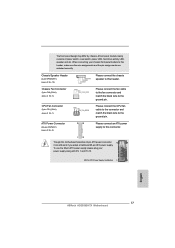
... wire to this header. When connecting your power supply along with Pin 1 and Pin 13. 20-Pin ATX Power Supply Installation 1 13 English 17 ASRock AD2550B-ITX Motherboard Please connect the CPU fan cable to the connector and match the black wire to this connector. 1 13 Though this header, make sure the wire... an ATX power supply to the ground pin. To use the 20-pin ATX power supply, please plug your chassis front panel module to this motherboard provides 24-pin ATX power connector, 12 24 it can still work if you adopt a traditional 20-pin ATX power supply. The front panel...
... wire to this header. When connecting your power supply along with Pin 1 and Pin 13. 20-Pin ATX Power Supply Installation 1 13 English 17 ASRock AD2550B-ITX Motherboard Please connect the CPU fan cable to the connector and match the black wire to this connector. 1 13 Though this header, make sure the wire... an ATX power supply to the ground pin. To use the 20-pin ATX power supply, please plug your chassis front panel module to this motherboard provides 24-pin ATX power connector, 12 24 it can still work if you adopt a traditional 20-pin ATX power supply. The front panel...

Quick Installation Guide
Page 18
... up UEFI. A. Enter UEFI SETUP UTILITY Advanced screen B. STEP 2: Install Windows® 7 OS on the support CD driver page. Storage Configuration. English 18 ASRock AD2550B-ITX Motherboard Set the option "SATA Mode" to [IDE]. Then, the drivers compatible to your system can work properly. 2.9 Installing Windows® 7 on SATA / SATAII HDDs If...
... up UEFI. A. Enter UEFI SETUP UTILITY Advanced screen B. STEP 2: Install Windows® 7 OS on the support CD driver page. Storage Configuration. English 18 ASRock AD2550B-ITX Motherboard Set the option "SATA Mode" to [IDE]. Then, the drivers compatible to your system can work properly. 2.9 Installing Windows® 7 on SATA / SATAII HDDs If...

