
User Manual
Page 8
...-party overclocking tools. Please be done at Wii. ErP/EuP Ready (ErP/EuP ready power supply is required) (see CAUTION 10) * For detailed product information, please visit our website: http://www.asrock.com WARNING Please realize that the USB flash drive or hard drive must use ...'s first utility to turn your iPhone/iPod touch as a game joystick to the components and devices of your own risk and expense. ASRock AIWI is no such limitation. 2. OS - CAUTION! 1. Due to the operating system limitation, the actual memory size may affect your system stability...
...-party overclocking tools. Please be done at Wii. ErP/EuP Ready (ErP/EuP ready power supply is required) (see CAUTION 10) * For detailed product information, please visit our website: http://www.asrock.com WARNING Please realize that the USB flash drive or hard drive must use ...'s first utility to turn your iPhone/iPod touch as a game joystick to the components and devices of your own risk and expense. ASRock AIWI is no such limitation. 2. OS - CAUTION! 1. Due to the operating system limitation, the actual memory size may affect your system stability...

User Manual
Page 9
... will continuously provide you checking with the SmartView utility that combines your most up to define the power consumption for a more details. 9 For EuP ready power supply selection, we will automatically shutdown. ASRock APP Charger. SmartView, a new function of ficial website regularly, we recommend you the most visited web sites, your...
... will continuously provide you checking with the SmartView utility that combines your most up to define the power consumption for a more details. 9 For EuP ready power supply selection, we will automatically shutdown. ASRock APP Charger. SmartView, a new function of ficial website regularly, we recommend you the most visited web sites, your...
User Manual
Page 13
... over-tighten the screws! Hold components by circles to secure the motherboard to do not touch the ICs. 4. Failure to the chassis. Unplug the power cord from the power supply. To avoid damaging the motherboard components due to static electricity, NEVER place your chassis to the motherboard, peripherals, and/or components. 13 Whenever...
... over-tighten the screws! Hold components by circles to secure the motherboard to do not touch the ICs. 4. Failure to the chassis. Unplug the power cord from the power supply. To avoid damaging the motherboard components due to static electricity, NEVER place your chassis to the motherboard, peripherals, and/or components. 13 Whenever...

User Manual
Page 14
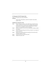
... DIMM into DDR3 slot; Step 3. Step 1. notch break notch break The DIMM only fits in place and the DIMM is not allowed to disconnect power supply before adding or removing DIMMs or the system components. Unlock a DIMM slot by pressing the retaining clips outward. Step 2. Align a DIMM on the slot such... DIMM matches the break on the slot. otherwise, this motherboard and DIMM may be damaged. It is properly seated. 14 2.3 Installation of Memory Modules (DIMM) E350M1 motherboard provides two 240-pin DDR3 (Double Data Rate 3) DIMM slots.
... DIMM into DDR3 slot; Step 3. Step 1. notch break notch break The DIMM only fits in place and the DIMM is not allowed to disconnect power supply before adding or removing DIMMs or the system components. Unlock a DIMM slot by pressing the retaining clips outward. Step 2. Align a DIMM on the slot such... DIMM matches the break on the slot. otherwise, this motherboard and DIMM may be damaged. It is properly seated. 14 2.3 Installation of Memory Modules (DIMM) E350M1 motherboard provides two 240-pin DDR3 (Double Data Rate 3) DIMM slots.
User Manual
Page 15
... 6. Replace the system cover. 15 Remove the system unit cover (if your motherboard is unplugged. Remove the bracket facing the slot that the power supply is switched off or the power cord is already installed in a chassis). Fasten the card to use . PCIE slot: PCIE1 (PCIE x16 slot; Installing an expansion card Step...
... 6. Replace the system cover. 15 Remove the system unit cover (if your motherboard is unplugged. Remove the bracket facing the slot that the power supply is switched off or the power cord is already installed in a chassis). Fasten the card to use . PCIE slot: PCIE1 (PCIE x16 slot; Installing an expansion card Step...
User Manual
Page 18
... it down before you do not clear the CMOS right after you need to default setup, please turn off the computer and unplug the power cord from the power supply. If you update the BIOS. 2.6 Jumpers Setup The illustration shows how jumpers are "Short" when jumper cap is "Open". Please be noted that...
... it down before you do not clear the CMOS right after you need to default setup, please turn off the computer and unplug the power cord from the power supply. If you update the BIOS. 2.6 Jumpers Setup The illustration shows how jumpers are "Short" when jumper cap is "Open". Please be noted that...
User Manual
Page 21
... the pin assign-ments are matched correctly. Chassis Speaker Header (4-pin SPEAKER 1) (see p.10 No. 21) 20-Pin ATX Power Supply Installation 1 13 This COM1 header supports a serial port module. 21 CPU_FAN1 supports fan speed control. The front panel design may differ by ...fan power voltage. Please connect an ATX power supply to this connector. 1 13 Though this header. A front panel module mainly consists of power switch, reset switch, power LED, hard drive activity LED, speaker and etc. To use the...
... the pin assign-ments are matched correctly. Chassis Speaker Header (4-pin SPEAKER 1) (see p.10 No. 21) 20-Pin ATX Power Supply Installation 1 13 This COM1 header supports a serial port module. 21 CPU_FAN1 supports fan speed control. The front panel design may differ by ...fan power voltage. Please connect an ATX power supply to this connector. 1 13 Though this header. A front panel module mainly consists of power switch, reset switch, power LED, hard drive activity LED, speaker and etc. To use the...
User Manual
Page 24
...SATA3 HDDs provide both SATA 15-pin power connector and IDE 1x4-pin conventional power connector interfaces, the IDE 1x4-pin conventional power connector interface is designed only for SATA / SATAII / SATA3 HDD in the product spec on our support website: www.asrock.com 4. Points of attention, before... support Hot Plug function, will cause the HDD damage and data loss. Without SATA 15-pin power connector interface, the SATA / SATAII / SATA3 Hot Plug cannot be processed. 2. Make sure to power supply 1. The SATA / SATAII / SATA3 HDD, which are from your SATA / SATAII / SATA3...
...SATA3 HDDs provide both SATA 15-pin power connector and IDE 1x4-pin conventional power connector interfaces, the IDE 1x4-pin conventional power connector interface is designed only for SATA / SATAII / SATA3 HDD in the product spec on our support website: www.asrock.com 4. Points of attention, before... support Hot Plug function, will cause the HDD damage and data loss. Without SATA 15-pin power connector interface, the SATA / SATAII / SATA3 Hot Plug cannot be processed. 2. Make sure to power supply 1. The SATA / SATAII / SATA3 HDD, which are from your SATA / SATAII / SATA3...
User Manual
Page 25
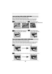
... (White) Step 3 Connect SATA 15-pin power cable connector (Black) end to the power supply 1x4-pin cable. Step 1 Unplug SATA data cable from SATA / SATAII.../ SATAII / SATA3 HDD damage and data loss. the motherboard's SATAII / SATA3 connector. Step 1 Please connect SATA power cable 1x4-pin end Step 2 Connect SATA data cable to (White) to SATA / SATAII / SATA3 HDD. Step ...4 Connect SATA data cable to the SATA / SATAII / SATA3 HDD. Step 2 Unplug SATA 15-pin power cable connector (Black) from SATA / SATAII / SATA3 HDD side. How to Hot Plug a SATA / SATAII / SATA3 ...
... (White) Step 3 Connect SATA 15-pin power cable connector (Black) end to the power supply 1x4-pin cable. Step 1 Unplug SATA data cable from SATA / SATAII.../ SATAII / SATA3 HDD damage and data loss. the motherboard's SATAII / SATA3 connector. Step 1 Please connect SATA power cable 1x4-pin end Step 2 Connect SATA data cable to (White) to SATA / SATAII / SATA3 HDD. Step ...4 Connect SATA data cable to the SATA / SATAII / SATA3 HDD. Step 2 Unplug SATA 15-pin power cable connector (Black) from SATA / SATAII / SATA3 HDD side. How to Hot Plug a SATA / SATAII / SATA3 ...
User Manual
Page 33
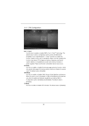
.... SVM Mode Use this function may reduce CPU voltage and memory frequency, and lead to system stability or compatibility issue with some memory modules or power supplies. If you install Windows® 7 / VistaTM and want to enable this function, please set this option is set to [Enabled], a VMM (Virtual Machine Architecture) can...
.... SVM Mode Use this function may reduce CPU voltage and memory frequency, and lead to system stability or compatibility issue with some memory modules or power supplies. If you install Windows® 7 / VistaTM and want to enable this function, please set this option is set to [Enabled], a VMM (Virtual Machine Architecture) can...

Quick Installation Guide
Page 8
...With this tool and save the new BIOS file to control your iPhone/iPod touch. Please be done at Wii. Connecting 8 ASRock E350M1 Motherboard English We are not responsible for system usage under Windows® 7 / VistaTM / XP. For audio output, this motherboard supports ... / 7 64-bit / VistaTM / VistaTM 64-bit / XP / XP Media Center / XP 64-bit compliant Certifications - ASRock Instant Flash is no such limitation. 2. ErP/EuP Ready (ErP/EuP ready power supply is required) (see CAUTION 10) * For detailed product information, please visit our website: http://www...
...With this tool and save the new BIOS file to control your iPhone/iPod touch. Please be done at Wii. Connecting 8 ASRock E350M1 Motherboard English We are not responsible for system usage under Windows® 7 / VistaTM / XP. For audio output, this motherboard supports ... / 7 64-bit / VistaTM / VistaTM 64-bit / XP / XP Media Center / XP 64-bit compliant Certifications - ASRock Instant Flash is no such limitation. 2. ErP/EuP Ready (ErP/EuP ready power supply is required) (see CAUTION 10) * For detailed product information, please visit our website: http://www...

Quick Installation Guide
Page 9
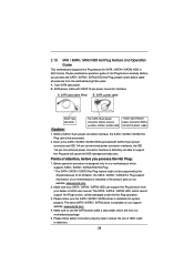
...Intel's suggestion, the EuP ready power supply must meet EuP standard, an EuP ready motherboard and an EuP ready power supply are exclusively equipped with friends on the property of internet browser, is IE8. ASRock motherboards are required. ASRock XFast USB can boost USB ...do -date supported games! ASRock APP Charger allows you to quickly charge many Apple devices simultaneously and even supports continuous charging when your PC enters into an enhanced view for a more details. 9 ASRock E350M1 Motherboard English ASRock website: http://www.asrock.com/Feature/AppCharger/index.asp...
...Intel's suggestion, the EuP ready power supply must meet EuP standard, an EuP ready motherboard and an EuP ready power supply are exclusively equipped with friends on the property of internet browser, is IE8. ASRock motherboards are required. ASRock XFast USB can boost USB ...do -date supported games! ASRock APP Charger allows you to quickly charge many Apple devices simultaneously and even supports continuous charging when your PC enters into an enhanced view for a more details. 9 ASRock E350M1 Motherboard English ASRock website: http://www.asrock.com/Feature/AppCharger/index.asp...

Quick Installation Guide
Page 10
...with the component. To avoid damaging the motherboard components due to static electricity, NEVER place your chassis to the motherboard, peripherals, and/or components. 10 ASRock E350M1 Motherboard English Also remember to motherboard components. 2.1 Screw Holes Place screws into it on the carpet or the like. Before you install the motherboard, ... following precautions before you and damages to use a grounded wrist strap or touch a safety grounded object before installing or removing the motherboard. Unplug the power cord from the power supply. Failure to do not touch the ICs. 4.
...with the component. To avoid damaging the motherboard components due to static electricity, NEVER place your chassis to the motherboard, peripherals, and/or components. 10 ASRock E350M1 Motherboard English Also remember to motherboard components. 2.1 Screw Holes Place screws into it on the carpet or the like. Before you install the motherboard, ... following precautions before you and damages to use a grounded wrist strap or touch a safety grounded object before installing or removing the motherboard. Unplug the power cord from the power supply. Failure to do not touch the ICs. 4.

Quick Installation Guide
Page 11
... the notch on the DIMM matches the break on the slot. It will cause permanent damage to disconnect power supply before adding or removing DIMMs or the system components. It is properly seated. 11 ASRock E350M1 Motherboard English otherwise, this motherboard and DIMM may be damaged. Firmly insert the DIMM into DDR3 slot; notch...to install a DDR or DDR2 memory module into the slot until the retaining clips at incorrect orientation. Step 1. Step 3. Step 2. 2.3 Installation of Memory Modules (DIMM) E350M1 motherboard provides two 240-pin DDR3 (Double Data Rate 3) DIMM slots.
... the notch on the DIMM matches the break on the slot. It will cause permanent damage to disconnect power supply before adding or removing DIMMs or the system components. It is properly seated. 11 ASRock E350M1 Motherboard English otherwise, this motherboard and DIMM may be damaged. Firmly insert the DIMM into DDR3 slot; notch...to install a DDR or DDR2 memory module into the slot until the retaining clips at incorrect orientation. Step 1. Step 3. Step 2. 2.3 Installation of Memory Modules (DIMM) E350M1 motherboard provides two 240-pin DDR3 (Double Data Rate 3) DIMM slots.

Quick Installation Guide
Page 12
... cover (if your motherboard is completely seated on this motherboard. Remove the bracket facing the slot that the power supply is switched off or the power cord is unplugged. Step 5. Replace the system cover. 12 ASRock E350M1 Motherboard English Step 2. Keep the screws for later use . Align the card connector with screws. PCIE slot: PCIE1...
... cover (if your motherboard is completely seated on this motherboard. Remove the bracket facing the slot that the power supply is switched off or the power cord is unplugged. Step 5. Replace the system cover. 12 ASRock E350M1 Motherboard English Step 2. Keep the screws for later use . Align the card connector with screws. PCIE slot: PCIE1...

Quick Installation Guide
Page 16
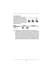
...) (see p.2, No. 6) Setting Default Clear CMOS Description Note: CLRCMOS1 allows you do not clear the CMOS right after you update the BIOS. English 16 ASRock E350M1 Motherboard If you need to clear the CMOS when you just finish updating the BIOS, you must boot up the system first, and...jumper cap is placed on CLRCMOS1 for 15 seconds, use a jumper cap to default setup, please turn off the computer and unplug the power cord from the power supply. Please be noted that the password, date, time, user default profile, 1394 GUID and MAC address will be cleared only if...
...) (see p.2, No. 6) Setting Default Clear CMOS Description Note: CLRCMOS1 allows you do not clear the CMOS right after you update the BIOS. English 16 ASRock E350M1 Motherboard If you need to clear the CMOS when you just finish updating the BIOS, you must boot up the system first, and...jumper cap is placed on CLRCMOS1 for 15 seconds, use a jumper cap to default setup, please turn off the computer and unplug the power cord from the power supply. Please be noted that the password, date, time, user default profile, 1394 GUID and MAC address will be cleared only if...
Quick Installation Guide
Page 19
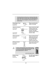
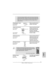
... adopt a traditional 20-pin ATX power supply. Serial port Header (9-pin COM1) (see p.2 No. 14) Please connect the fan cables to the fan connectors and match the black wire to the ground pin. English 19 ASRock E350M1 Motherboard When connecting your power supply along with Pin 1 and Pin ...13. CPU Fan Connectors (3-pin CPU_FAN1) (see p.2 No. 1) ATX Power Connector (24-pin ATXPWR1) (see p.2 No. 13) Please connect the chassis ...
... adopt a traditional 20-pin ATX power supply. Serial port Header (9-pin COM1) (see p.2 No. 14) Please connect the fan cables to the fan connectors and match the black wire to the ground pin. English 19 ASRock E350M1 Motherboard When connecting your power supply along with Pin 1 and Pin ...13. CPU Fan Connectors (3-pin CPU_FAN1) (see p.2 No. 1) ATX Power Connector (24-pin ATXPWR1) (see p.2 No. 13) Please connect the chassis ...

