
User Manual
Page 13
...USB 28 AUDIO CODEC HDMI_SPDIF1 1 PCI1 27 X X Fast RAM Fast LAN PCI2 10 RoHS Front USB 3.0 11 12 13 Intel H77 64Mb BIOS 14 26 ErP/EuP Ready H77M 15 Super I/O IR1 1 COM1 1 1 LPT1 PCIE2 CHA_FAN1 USB8_9 1 USB6_7 1 1 CIR1 CLRCMOS1 1 SPEAKER1 1 PLED ...CMOS Jumper (CLRCMOS1) 2 CPU Fan Connector (CPU_FAN1) 19 USB 2.0 Header (USB6_7, Black) 3 CPU Fan Connector (CPU_FAN2) 20 Consumer Infrared Module Header 4 1155-Pin CPU Socket (CIR1, Gray) 5 2 x 240-pin DDR3 DIMM Slots 21 USB 2.0 Header (USB8_9, Black) (DDR3_A1, DDR3_B1, Black) 22 Chassis Fan Connector (CHA_FAN1...
...USB 28 AUDIO CODEC HDMI_SPDIF1 1 PCI1 27 X X Fast RAM Fast LAN PCI2 10 RoHS Front USB 3.0 11 12 13 Intel H77 64Mb BIOS 14 26 ErP/EuP Ready H77M 15 Super I/O IR1 1 COM1 1 1 LPT1 PCIE2 CHA_FAN1 USB8_9 1 USB6_7 1 1 CIR1 CLRCMOS1 1 SPEAKER1 1 PLED ...CMOS Jumper (CLRCMOS1) 2 CPU Fan Connector (CPU_FAN1) 19 USB 2.0 Header (USB6_7, Black) 3 CPU Fan Connector (CPU_FAN2) 20 Consumer Infrared Module Header 4 1155-Pin CPU Socket (CIR1, Gray) 5 2 x 240-pin DDR3 DIMM Slots 21 USB 2.0 Header (USB8_9, Black) (DDR3_A1, DDR3_B1, Black) 22 Chassis Fan Connector (CHA_FAN1...
User Manual
Page 17
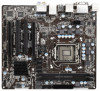
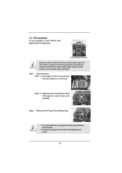
... the cap tab to flip up the load plate. Open the socket: Step 1-1. Step 2. Otherwise, the CPU will be placed if returning the motherboard for after service. 17 Disengage the lever by pressing it down and sliding it out of Intel 1155-Pin CPU, please follow the steps below. Step 1. Keep the... lever positioned at about 135 degrees in the socket. This cap must be seriously damaged. Do not force to insert the CPU into the...
... the cap tab to flip up the load plate. Open the socket: Step 1-1. Step 2. Otherwise, the CPU will be placed if returning the motherboard for after service. 17 Disengage the lever by pressing it down and sliding it out of Intel 1155-Pin CPU, please follow the steps below. Step 1. Keep the... lever positioned at about 135 degrees in the socket. This cap must be seriously damaged. Do not force to insert the CPU into the...

User Manual
Page 19
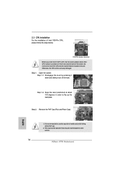
...clockwise, the heatsink cannot be noticed that supports Intel 1155-Pin CPUs. Connect fan header with thumb to adopt three different CPU cooler types, Socket LGA 775, LGA 1155 and LGA 1156. Ensure that the CPU and the heatsink are for 1155-Pin CPUs. No. 3). Step 6. Apply ... which provides flexible options to install and lock. Then connect the CPU fan to illustrate the installation of the heatsink for Socket LGA 1155/1156 CPU fan. 19 Apply Thermal Interface Material Step 2. Please be secured on the motherboard. 2.4 Installation of CPU Fan and...
...clockwise, the heatsink cannot be noticed that supports Intel 1155-Pin CPUs. Connect fan header with thumb to adopt three different CPU cooler types, Socket LGA 775, LGA 1155 and LGA 1156. Ensure that the CPU and the heatsink are for 1155-Pin CPUs. No. 3). Step 6. Apply ... which provides flexible options to install and lock. Then connect the CPU fan to illustrate the installation of the heatsink for Socket LGA 1155/1156 CPU fan. 19 Apply Thermal Interface Material Step 2. Please be secured on the motherboard. 2.4 Installation of CPU Fan and...

Quick Installation Guide
Page 2
... (CLRCMOS1) 2 CPU Fan Connector (CPU_FAN1) 19 USB 2.0 Header (USB6_7, Black) 3 CPU Fan Connector (CPU_FAN2) 20 Consumer Infrared Module Header 4 1155-Pin CPU Socket (CIR1, Gray) 5 2 x 240-pin DDR3 DIMM Slots 21 USB 2.0 Header (USB8_9, Black) (DDR3_A1, DDR3_B1, Black) 22 Chassis Fan Connector... Black) 14 SPI Flash Memory (64Mb) 30 Front Panel Audio Header 15 Intel H77 Chipset (HD_AUDIO1, Black) 16 System Panel Header (PANEL1, Black) 31 Chassis Fan Connector (CHA_FAN2) 17 Chassis Speaker Header (SPEAKER1, Black) 32 Power Fan Connector (PWR_FAN1) 2 ASRock H77M Motherboard English
... (CLRCMOS1) 2 CPU Fan Connector (CPU_FAN1) 19 USB 2.0 Header (USB6_7, Black) 3 CPU Fan Connector (CPU_FAN2) 20 Consumer Infrared Module Header 4 1155-Pin CPU Socket (CIR1, Gray) 5 2 x 240-pin DDR3 DIMM Slots 21 USB 2.0 Header (USB8_9, Black) (DDR3_A1, DDR3_B1, Black) 22 Chassis Fan Connector... Black) 14 SPI Flash Memory (64Mb) 30 Front Panel Audio Header 15 Intel H77 Chipset (HD_AUDIO1, Black) 16 System Panel Header (PANEL1, Black) 31 Chassis Fan Connector (CHA_FAN2) 17 Chassis Speaker Header (SPEAKER1, Black) 32 Power Fan Connector (PWR_FAN1) 2 ASRock H77M Motherboard English
Quick Installation Guide
Page 14
...the lever by pressing it down and sliding it out of Intel 1155-Pin CPU, please follow the steps below. This cap must be seriously damaged. Open the socket: Step 1-1. Step 2. Keep the lever positioned at about 135 degrees in the socket. Remove the PnP Cap (Pick and Place Cap). Do not... force to insert the CPU into the socket, please check if the CPU surface is found. Otherwise, the CPU will be placed if returning the motherboard for after service. 14 ASRock H77M Motherboard Step 1-2.
...the lever by pressing it down and sliding it out of Intel 1155-Pin CPU, please follow the steps below. This cap must be seriously damaged. Open the socket: Step 1-1. Step 2. Keep the lever positioned at about 135 degrees in the socket. Remove the PnP Cap (Pick and Place Cap). Do not... force to insert the CPU into the socket, please check if the CPU surface is found. Otherwise, the CPU will be placed if returning the motherboard for after service. 14 ASRock H77M Motherboard Step 1-2.

Quick Installation Guide
Page 16
...an example to illustrate the installation of the heatsink for Socket LGA 1155/1156 CPU fan. 16 ASRock H77M Motherboard No. 3). Step 1. Apply Thermal Interface Material Step 2. No. 3). Step 6. Please be secured on fastener caps with Intel 1155Pin CPU to improve heat dissipation. Align fasteners with ... your CPU fan and heatsink. Place the heatsink onto the socket. Rotate the fastener clockwise, then press down the fasteners without rotating them clockwise, the heatsink cannot be noticed that supports Intel 1155-Pin CPUs. Fan cables on side closest to MB header Fastener...
...an example to illustrate the installation of the heatsink for Socket LGA 1155/1156 CPU fan. 16 ASRock H77M Motherboard No. 3). Step 1. Apply Thermal Interface Material Step 2. No. 3). Step 6. Please be secured on fastener caps with Intel 1155Pin CPU to improve heat dissipation. Align fasteners with ... your CPU fan and heatsink. Place the heatsink onto the socket. Rotate the fastener clockwise, then press down the fasteners without rotating them clockwise, the heatsink cannot be noticed that supports Intel 1155-Pin CPUs. Fan cables on side closest to MB header Fastener...


