
User Manual
Page 3
...1.1 Package Contents 4 1.2 Specifications 5 1.3 Motherboard Layout (K7S41 7 1.4 Motherboard Layout (K7S41GX 8 1.5 ASRock I/OTM (K7S41 / K7S41GX 9 2 Installation 10 Pre-installation Precautions 10 2.1 CPU Installation 11 2.2 Installation of CPU Fan and Heatsink 11 2.3 Installation of Memory Modules (DIMM 12 2.4 Expansion Slots (PCI, AMR, ... System 23 4.2 Support CD Information 23 4.2.1 Running Support CD 23 4.2.2 Drivers Menu 23 4.2.3 Utilities Menu 23 4.2.4 ASRock "PC-DIY Live Demo" Program 23 4.2.5 Contact Information 23 Appendix 24 1. Advanced BIOS Setup Menu 24 2. Power ...
...1.1 Package Contents 4 1.2 Specifications 5 1.3 Motherboard Layout (K7S41 7 1.4 Motherboard Layout (K7S41GX 8 1.5 ASRock I/OTM (K7S41 / K7S41GX 9 2 Installation 10 Pre-installation Precautions 10 2.1 CPU Installation 11 2.2 Installation of CPU Fan and Heatsink 11 2.3 Installation of Memory Modules (DIMM 12 2.4 Expansion Slots (PCI, AMR, ... System 23 4.2 Support CD Information 23 4.2.1 Running Support CD 23 4.2.2 Drivers Menu 23 4.2.3 Utilities Menu 23 4.2.4 ASRock "PC-DIY Live Demo" Program 23 4.2.5 Contact Information 23 Appendix 24 1. Advanced BIOS Setup Menu 24 2. Power ...

User Manual
Page 4
...-bystep installation guide. You may find the latest memory and CPU support lists on page 24 for advanced users' reference. ASRock website http://www.asrock.com 1.1 Package Contents ASRock K7S41 or K7S41GX Motherboard (Micro ATX Form Factor: 9.6-in x 7.8-in, 24.4 cm x 19.8 cm) ASRock K7S41 / K7S41GX Quick Installation Guide ASRock K7S41 / K7S41GX Support CD One 80-conductor Ultra ATA...
...-bystep installation guide. You may find the latest memory and CPU support lists on page 24 for advanced users' reference. ASRock website http://www.asrock.com 1.1 Package Contents ASRock K7S41 or K7S41GX Motherboard (Micro ATX Form Factor: 9.6-in x 7.8-in, 24.4 cm x 19.8 cm) ASRock K7S41 / K7S41GX Quick Installation Guide ASRock K7S41 / K7S41GX Support CD One 80-conductor Ultra ATA...

User Manual
Page 7
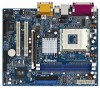
... FSB_SEL1 1 FSB_SEL0 SiS 741 Chipset AGP 8X 1.5V_AGP1 ` ATA133 IDE2 IDE1 AUDIO CODEC AUDIO1 1 JR1 JL1 COM1 1 2MB BIOS PCI 1 PCI 2 SiS 963L K7S41 Super I/O IR1 AMR1 1 FSB400 DDR400 USB45 1 CMOS CLRCMOS1 Battery 5.1CH CLRCMOS2 FLOPPY1 USB 2.0 CHA_FAN1 PWR_LED1 1 PLED PWRBTN SPEAKER1 PANEL 1 1 1 HDLED RST ... 1) 17 Floppy Connector (FLOPPY1) 18 USB 2.0 Connector (USB45, Blue) 19 Infrared Module Connector (IR1) 20 AMR Slot (AMR1) 21 Flash Memory 22 Serial Port Connector (COM1) 23 JL1 Jumper 24 JR1 Jumper 25 Front Panel Audio Connector (AUDIO1) 26 PCI Slots (PCI 1- 2) 27 ...
... FSB_SEL1 1 FSB_SEL0 SiS 741 Chipset AGP 8X 1.5V_AGP1 ` ATA133 IDE2 IDE1 AUDIO CODEC AUDIO1 1 JR1 JL1 COM1 1 2MB BIOS PCI 1 PCI 2 SiS 963L K7S41 Super I/O IR1 AMR1 1 FSB400 DDR400 USB45 1 CMOS CLRCMOS1 Battery 5.1CH CLRCMOS2 FLOPPY1 USB 2.0 CHA_FAN1 PWR_LED1 1 PLED PWRBTN SPEAKER1 PANEL 1 1 1 HDLED RST ... 1) 17 Floppy Connector (FLOPPY1) 18 USB 2.0 Connector (USB45, Blue) 19 Infrared Module Connector (IR1) 20 AMR Slot (AMR1) 21 Flash Memory 22 Serial Port Connector (COM1) 23 JL1 Jumper 24 JR1 Jumper 25 Front Panel Audio Connector (AUDIO1) 26 PCI Slots (PCI 1- 2) 27 ...

User Manual
Page 8
...) 8 16 Chassis Speaker Connector (SPEAKER 1) 17 Floppy Connector (FLOPPY1) 18 USB 2.0 Connector (USB45, Blue) 19 Infrared Module Connector (IR1) 20 AMR Slot (AMR1) 21 Flash Memory 22 Serial Port Connector (COM1) 23 JL1 Jumper 24 JR1 Jumper 25 Front Panel Audio Connector (AUDIO1) 26 PCI Slots (PCI 1- 2) 27 FSB Select Jumpers...
...) 8 16 Chassis Speaker Connector (SPEAKER 1) 17 Floppy Connector (FLOPPY1) 18 USB 2.0 Connector (USB45, Blue) 19 Infrared Module Connector (IR1) 20 AMR Slot (AMR1) 21 Flash Memory 22 Serial Port Connector (COM1) 23 JL1 Jumper 24 JR1 Jumper 25 Front Panel Audio Connector (AUDIO1) 26 PCI Slots (PCI 1- 2) 27 FSB Select Jumpers...

User Manual
Page 12
... one correct orientation. Step 2. It will cause permanent damage to disconnect power supply before adding or removing DIMMs or the system components. 2.3 Installation of Memory Modules (DIMM) K7S41 / K7S41GX motherboard provides two 184-pin DDR (Double Data Rate) DIMM slots. Please make sure to the motherboard and the DIMM if you force...
... one correct orientation. Step 2. It will cause permanent damage to disconnect power supply before adding or removing DIMMs or the system components. 2.3 Installation of Memory Modules (DIMM) K7S41 / K7S41GX motherboard provides two 184-pin DDR (Double Data Rate) DIMM slots. Please make sure to the motherboard and the DIMM if you force...

User Manual
Page 19
.... Please press during the PowerOn-Self-Test (POST) to enter the BIOS Setup Utility, otherwise, POST will continue with their corresponding functions. 19 The Flash Memory on the system chassis. Chapter 3 BIOS Setup 3.1 BIOS Setup Utility This section explains how to use the BIOS Setup Utility to configure your screen. 3.1.1 BIOS...
.... Please press during the PowerOn-Self-Test (POST) to enter the BIOS Setup Utility, otherwise, POST will continue with their corresponding functions. 19 The Flash Memory on the system chassis. Chapter 3 BIOS Setup 3.1 BIOS Setup Utility This section explains how to use the BIOS Setup Utility to configure your screen. 3.1.1 BIOS...

User Manual
Page 20
Dec Day: 01 - 31 Year: 1980 - 2099 K7S41 BIOS P1.00 AMD Athlon(tm) XP 2600+ 2133 MHz 128 KB 256 KB 480 MB + 32 MB Share Memory 512 MB / 133 MHz (DDR 266) None F1:Help Esc:Exit :Select Item :Select Menu +/-:Change Values Enter:Select Sub-Menu F9:Setup... drives installed. Main Advanced System Date System Time Floppy Drives IDE Devices BIOS Version Processor Type Processor Speed L1 Cache Size L2 Cache Size Total Memory DDR1 DDR2 AMIBIOS SETUP UTILITY - Use keys to move between the Hour, Minute, and Second fields. Navigation Key(s) / / + / Function Description Displays the ...
Dec Day: 01 - 31 Year: 1980 - 2099 K7S41 BIOS P1.00 AMD Athlon(tm) XP 2600+ 2133 MHz 128 KB 256 KB 480 MB + 32 MB Share Memory 512 MB / 133 MHz (DDR 266) None F1:Help Esc:Exit :Select Item :Select Menu +/-:Change Values Enter:Select Sub-Menu F9:Setup... drives installed. Main Advanced System Date System Time Floppy Drives IDE Devices BIOS Version Processor Type Processor Speed L1 Cache Size L2 Cache Size Total Memory DDR1 DDR2 AMIBIOS SETUP UTILITY - Use keys to move between the Hour, Minute, and Second fields. Navigation Key(s) / / + / Function Description Displays the ...

User Manual
Page 24
... Values Enter:Select Sub-Menu F9:Setup Defaults F10:Save & Exit Spread Spectrum: This field should always be available only when K7S41 motherboard is not recommended unless you must set to [Auto], the motherboard will allow better tolerance for better system stability. You... may cause problems during operation. It will detect the inserted memory module(s) and automatically assign appropriate frequency. However, because the CPU host frequency of this motherboard is set CPU host frequency manually....
... Values Enter:Select Sub-Menu F9:Setup Defaults F10:Save & Exit Spread Spectrum: This field should always be available only when K7S41 motherboard is not recommended unless you must set to [Auto], the motherboard will allow better tolerance for better system stability. You... may cause problems during operation. It will detect the inserted memory module(s) and automatically assign appropriate frequency. However, because the CPU host frequency of this motherboard is set CPU host frequency manually....

User Manual
Page 25
...the default value unless the installed AGP card's specifications requires other sizes. USB Device Legacy Support: Use this to a section of share memory for graphics memory. Please note that not all the DDR DIMMs can support CAS latency=3T. AGP Aperture Size: It refers to enable or disable ... VGA. Over Vcore Voltage: This feature allows you to enable or disable USB 2.0 controller. If this to select the size of the PCI memory address range used to emulate legacy I/O devices such as mouse, keyboard,... DRAM CAS Latency: This is not recommended to leave this field at ...
...the default value unless the installed AGP card's specifications requires other sizes. USB Device Legacy Support: Use this to a section of share memory for graphics memory. Please note that not all the DDR DIMMs can support CAS latency=3T. AGP Aperture Size: It refers to enable or disable ... VGA. Over Vcore Voltage: This feature allows you to enable or disable USB 2.0 controller. If this to select the size of the PCI memory address range used to emulate legacy I/O devices such as mouse, keyboard,... DRAM CAS Latency: This is not recommended to leave this field at ...

User Manual
Page 30
Boot Up Num-Lock: If this is enabled, it will speed up the boot-up routine by skipping memory retestings. Boot Device Priority: This allows you to enable or disable "boot from network" feature. Boot From Network: Use this mode will automatically activate the ...
Boot Up Num-Lock: If this is enabled, it will speed up the boot-up routine by skipping memory retestings. Boot Device Priority: This allows you to enable or disable "boot from network" feature. Boot From Network: Use this mode will automatically activate the ...

