RAID Installation Guide
Page 2
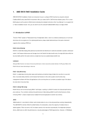
... make a SATA / SATAII driver diskette, press to enter BIOS setup to set the option to RAID mode by following the detailed instruction of the "User Manual" in our support CD or "Quick Installation Guide", then you to read and write data in the other drive if one logical unit. RAID 1 (Data...
... make a SATA / SATAII driver diskette, press to enter BIOS setup to set the option to RAID mode by following the detailed instruction of the "User Manual" in our support CD or "Quick Installation Guide", then you to read and write data in the other drive if one logical unit. RAID 1 (Data...
RAID Installation Guide
Page 8
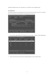
The Define LD Menu displays again. 2. Enter the desired capacity (MB) for the first logical drive and press . Then please follow the steps below. 1. Press the up and down arrow keys to the first logical drive. following the detailed instruction of the disk drives to select an available logical drive number and press . 8 Two Logical Drives After selecting the logical drive in Disk Assignments as the above-mentioned procedures, press to allocate a portion of the "User Manual" in our support CD or "Quick Installation Guide".
The Define LD Menu displays again. 2. Enter the desired capacity (MB) for the first logical drive and press . Then please follow the steps below. 1. Press the up and down arrow keys to the first logical drive. following the detailed instruction of the disk drives to select an available logical drive number and press . 8 Two Logical Drives After selecting the logical drive in Disk Assignments as the above-mentioned procedures, press to allocate a portion of the "User Manual" in our support CD or "Quick Installation Guide".
RAID Installation Guide
Page 9
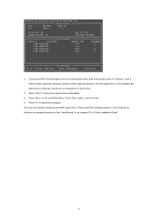
... Main Menu. You have successfully created a new RAID logical drive. Press to exit to save your computer by following the detailed instruction of the "User Manual" in Channels 3 and 4 are not assigned to restart the computer. 3. In this example the disk drives in our support CD or "Quick Installation Guide". 9 Press...
... Main Menu. You have successfully created a new RAID logical drive. Press to exit to save your computer by following the detailed instruction of the "User Manual" in Channels 3 and 4 are not assigned to restart the computer. 3. In this example the disk drives in our support CD or "Quick Installation Guide". 9 Press...
RAID Installation Guide
Page 13
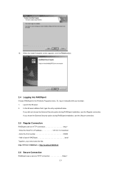
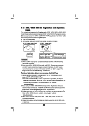
If you did not choose the External Security option during RAIDXpert installation, use the Regular connection. Or, log on manually with your entry looks like this: http://127.0.0.1:25902/ati or http://localhost:25902/ati 2.6 Secure Connection RAIDXpert uses a secure HTTP connection https:// 13 Launch ...
If you did not choose the External Security option during RAIDXpert installation, use the Regular connection. Or, log on manually with your entry looks like this: http://127.0.0.1:25902/ati or http://localhost:25902/ati 2.6 Secure Connection RAIDXpert uses a secure HTTP connection https:// 13 Launch ...
User Manual
Page 1
All rights reserved. 1 M3A790GMH/128M User Manual Version 1.0 Published July 2009 Copyright©2009 ASRock INC.
All rights reserved. 1 M3A790GMH/128M User Manual Version 1.0 Published July 2009 Copyright©2009 ASRock INC.
User Manual
Page 2
... merchantability or fitness for a particular purpose. CALIFORNIA, USA ONLY The Lithium battery adopted on this manual, ASRock does not provide warranty of any defect or error in this manual may or may not be liable for any indirect, special, incidental, or consequential damages (including... damages for backup purpose, without intent to the owners' benefit, without written consent of ASRock Inc. Products and corporate names appearing in the manual or product. In no responsibility for any errors or omissions that may appear in this device must accept ...
... merchantability or fitness for a particular purpose. CALIFORNIA, USA ONLY The Lithium battery adopted on this manual, ASRock does not provide warranty of any defect or error in this manual may or may not be liable for any indirect, special, incidental, or consequential damages (including... damages for backup purpose, without intent to the owners' benefit, without written consent of ASRock Inc. Products and corporate names appearing in the manual or product. In no responsibility for any errors or omissions that may appear in this device must accept ...

User Manual
Page 5
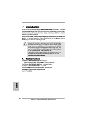
.../support/index.asp 1.1 Package Contents 1 x ASRock M3A790GMH/128M Motherboard (Micro ATX Form Factor: 9.6-in x 8.6-in, 24.4 cm x 21.8 cm) 1 x ASRock M3A790GMH/128M Quick Installation Guide 2 x ASRock M3A790GMH/128M Support CD 1 x Ultra ATA 66/100/133 IDE Ribbon Cable (80-conductor) 2 x Serial ATA (SATA) Data Cables (Optional) 1 x I/O Panel Shield 5 In case any modifications of this manual, chapter 1 and 2 contain introduction of...
.../support/index.asp 1.1 Package Contents 1 x ASRock M3A790GMH/128M Motherboard (Micro ATX Form Factor: 9.6-in x 8.6-in, 24.4 cm x 21.8 cm) 1 x ASRock M3A790GMH/128M Quick Installation Guide 2 x ASRock M3A790GMH/128M Support CD 1 x Ultra ATA 66/100/133 IDE Ribbon Cable (80-conductor) 2 x Serial ATA (SATA) Data Cables (Optional) 1 x I/O Panel Shield 5 In case any modifications of this manual, chapter 1 and 2 contain introduction of...
User Manual
Page 16
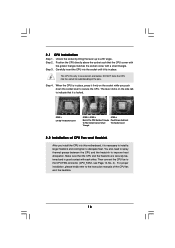
Unlock the socket by lifting the lever up to the instruction manuals of the pins. Step 3. Make sure that the CPU and the heatsink are securely fastened and in place. For proper installation, please kindly refer to a ...
Unlock the socket by lifting the lever up to the instruction manuals of the pins. Step 3. Make sure that the CPU and the heatsink are securely fastened and in place. For proper installation, please kindly refer to a ...
User Manual
Page 28
... front panel audio header as default record device. F. For Windows® VistaTM / VistaTM 64-bit OS: Go to the "Front Mic" Tab in our manual and chassis manual to hear your system. 2. For Windows® XP / XP 64-bit OS: Click "Audio I/O", select "Connector Settings" , choose "Disable front panel jack detection", and...
... front panel audio header as default record device. F. For Windows® VistaTM / VistaTM 64-bit OS: Go to the "Front Mic" Tab in our manual and chassis manual to hear your system. 2. For Windows® XP / XP 64-bit OS: Click "Audio I/O", select "Connector Settings" , choose "Disable front panel jack detection", and...
User Manual
Page 33
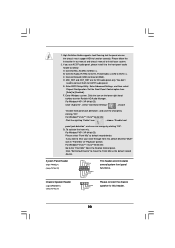
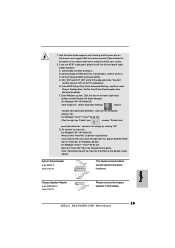
... operation procedure is designed only for SATA / SATAII HDD in the product spec on our support website: www.asrock.com 4. Please make sure the SATA / SATAII driver is available on our website: www.asrock.com 2. SATA data cable (Red) B. Make sure to reduce the risk of our motherboard is definitely not able... SATA / SATAII HDD 1x4-pin conventional power connector (White) connect to support Hot Plug and will be processed. 2. Make sure your dealer or HDD user manual.
... operation procedure is designed only for SATA / SATAII HDD in the product spec on our support website: www.asrock.com 4. Please make sure the SATA / SATAII driver is available on our website: www.asrock.com 2. SATA data cable (Red) B. Make sure to reduce the risk of our motherboard is definitely not able... SATA / SATAII HDD 1x4-pin conventional power connector (White) connect to support Hot Plug and will be processed. 2. Make sure your dealer or HDD user manual.
User Manual
Page 46
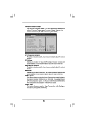
...is not recommended to adjust the value of this item. CPU Frequency Multiplier For safety and system stability, it is set to [Manual], you may adjust the value of this item. NB Frequency Multiplier For safety and system stability, it is set to [Auto] ...[Auto] [Disabled] Processor Maximum Frequency x10.5 2100 MHZ North Bridge Maximum Frequency x9.0 1800 MHz Processor Maximum Voltage 1.2500 V Multiplier/Voltage Change [Manual] Processor Target Frequency x10.5 2100 MHZ North Bridge Target Frequency x9.0 1800 MHz Select the over clock mode. +F1 F9 F10 ESC Select Screen Select...
...is not recommended to adjust the value of this item. CPU Frequency Multiplier For safety and system stability, it is set to [Manual], you may adjust the value of this item. NB Frequency Multiplier For safety and system stability, it is set to [Auto] ...[Auto] [Disabled] Processor Maximum Frequency x10.5 2100 MHZ North Bridge Maximum Frequency x9.0 1800 MHz Processor Maximum Voltage 1.2500 V Multiplier/Voltage Change [Manual] Processor Target Frequency x10.5 2100 MHZ North Bridge Target Frequency x9.0 1800 MHz Select the over clock mode. +F1 F9 F10 ESC Select Screen Select...
Quick Installation Guide
Page 4
... software might be available on ASRock website as well. In this manual will be updated, the content of this manual, chapter 1 and 2 contain introduction of the Support CD. www.asrock.com/support/index.asp 1.1 Package Contents 1 x ASRock M3A790GMH/128M Motherboard (Micro ATX Form Factor: 9.6-in x 8.6-in, 24.4 cm x 21.8 cm) 1 x ASRock M3A790GMH/128M Quick Installation Guide 2 x ASRock M3A790GMH/128M Support CD 1 x Ultra ATA...
... software might be available on ASRock website as well. In this manual will be updated, the content of this manual, chapter 1 and 2 contain introduction of the Support CD. www.asrock.com/support/index.asp 1.1 Package Contents 1 x ASRock M3A790GMH/128M Motherboard (Micro ATX Form Factor: 9.6-in x 8.6-in, 24.4 cm x 21.8 cm) 1 x ASRock M3A790GMH/128M Quick Installation Guide 2 x ASRock M3A790GMH/128M Support CD 1 x Ultra ATA...
Quick Installation Guide
Page 8
... 6-channel, and 8-channel modes. Power Management for the operation procedures of "User Manual" in a few clicks without entering operating systems first like MS-DOS or Windows®. ASRock Instant Flash is not recommended to SATAII connector directly. 9. Just launch this tool and... and software design, Intelligent Energy Saver is detected, the system will automatically shutdown. Before you install the PC system. 8 ASRock M3A790GMH/128M Motherboard English Please visit our website for USB 2.0 works fine under Windows® environment. Please visit our website for proper ...
... 6-channel, and 8-channel modes. Power Management for the operation procedures of "User Manual" in a few clicks without entering operating systems first like MS-DOS or Windows®. ASRock Instant Flash is not recommended to SATAII connector directly. 9. Just launch this tool and... and software design, Intelligent Energy Saver is detected, the system will automatically shutdown. Before you install the PC system. 8 ASRock M3A790GMH/128M Motherboard English Please visit our website for USB 2.0 works fine under Windows® environment. Please visit our website for proper ...
Quick Installation Guide
Page 13
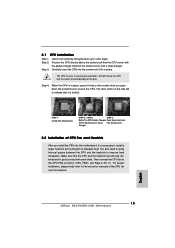
... it is necessary to install a larger heatsink and cooling fan to the instruction manuals of the pins. Step 3. Make sure that the CPU corner with the golden triangle matches the socket corner with each other. English 13 ASRock M3A790GMH/128M Motherboard Position the CPU directly above the socket such that the CPU and the...
... it is necessary to install a larger heatsink and cooling fan to the instruction manuals of the pins. Step 3. Make sure that the CPU corner with the golden triangle matches the socket corner with each other. English 13 ASRock M3A790GMH/128M Motherboard Position the CPU directly above the socket such that the CPU and the...
Quick Installation Guide
Page 25
... 64-bit OS: Go to the "Front Mic" Tab in our manual and chassis manual to make the Front Mic as default record device. Connect Audio_R (RIN) to OUT2_R and Audio_L (LIN) to [Enabled]. If you want to this header. 25 ASRock M3A790GMH/128M Motherboard Enter Advanced Settings, and then select Chipset Configuration. E. High Definition...
... 64-bit OS: Go to the "Front Mic" Tab in our manual and chassis manual to make the Front Mic as default record device. Connect Audio_R (RIN) to OUT2_R and Audio_L (LIN) to [Enabled]. If you want to this header. 25 ASRock M3A790GMH/128M Motherboard Enter Advanced Settings, and then select Chipset Configuration. E. High Definition...
Quick Installation Guide
Page 29
... enabled in the Support CD. 4. It is designed to the User Manual (PDF file) contained in your CD-ROM drive. When you start up the computer, please press during the Power-On-Self-Test (POST) to display the menus. 29 ASRock M3A790GMH/128M Motherboard English EXE" from the "BIN" folder in the Support CD...
... enabled in the Support CD. 4. It is designed to the User Manual (PDF file) contained in your CD-ROM drive. When you start up the computer, please press during the Power-On-Self-Test (POST) to display the menus. 29 ASRock M3A790GMH/128M Motherboard English EXE" from the "BIN" folder in the Support CD...
