
User Manual
Page 3
... Exit Menu 32 3 Advanced BIOS Setup Menu 24 2. Boot Setup Menu 31 5. Contents 1 Introduction 4 1.1 Package Contents 4 1.2 Specifications 5 1.3 Motherboard Layout 8 1.4 ASRock I/OTM 9 2 Installation 10 2.1 Screw Holes 10 2.2 Pre-installation Precautions 10 2.3 CPU Installation 11 2.4 Installation of CPU Fan and Heatsink 11 ... Operating System 23 4.2 Support CD Information 23 4.2.1 Running Support CD 23 4.2.2 Drivers Menu 23 4.2.3 Utilities Menu 23 4.2.4 ASRock "PC-DIY Live Demo" Program 23 4.2.5 Contact Information 23 Appendix 24 1. Security Setup Menu 29 3.
... Exit Menu 32 3 Advanced BIOS Setup Menu 24 2. Boot Setup Menu 31 5. Contents 1 Introduction 4 1.1 Package Contents 4 1.2 Specifications 5 1.3 Motherboard Layout 8 1.4 ASRock I/OTM 9 2 Installation 10 2.1 Screw Holes 10 2.2 Pre-installation Precautions 10 2.3 CPU Installation 11 2.4 Installation of CPU Fan and Heatsink 11 ... Operating System 23 4.2 Support CD Information 23 4.2.1 Running Support CD 23 4.2.2 Drivers Menu 23 4.2.3 Utilities Menu 23 4.2.4 ASRock "PC-DIY Live Demo" Program 23 4.2.5 Contact Information 23 Appendix 24 1. Security Setup Menu 29 3.

User Manual
Page 4
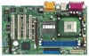
... 1 Introduction Thank you for a 3.5-in , 30.5 cm x 17.8 cm) ASRock P4i45PE+ Quick Installation Guide ASRock P4i45PE+ Support CD One 80-conductor Ultra ATA 66/100 IDE Ribbon Cable One Ribbon Cable for purchasing ASRock P4i45PE+ motherboard, a reliable motherboard produced under ASRock's consistently stringent quality control. Chapter 1 and 2 of the motherboard and step-bystep installation guide. For advanced users' reference, the...
... 1 Introduction Thank you for a 3.5-in , 30.5 cm x 17.8 cm) ASRock P4i45PE+ Quick Installation Guide ASRock P4i45PE+ Support CD One 80-conductor Ultra ATA 66/100 IDE Ribbon Cable One Ribbon Cable for purchasing ASRock P4i45PE+ motherboard, a reliable motherboard produced under ASRock's consistently stringent quality control. Chapter 1 and 2 of the motherboard and step-bystep installation guide. For advanced users' reference, the...
User Manual
Page 6
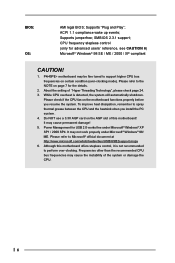
... higher CPU bus frequencies on page 7 for advanced users' reference, see CAUTION 6) Microsoft® Windows® 98 SE / ME / 2000 / XP compliant CAUTION! 1. P4i45PE+ motherboard may cause the instability of the system or damage the CPU. 6 About the setting of this...check if the CPU fan on the AGP slot of "Hyper Threading Technology", please check page 24. 3. Do NOT use a 3.3V AGP card on the motherboard functions properly before you install the PC system. 4. Supports "Plug and Play"; Supports jumperfree; ACPI 1.1 compliance wake up events; To improve heat dissipation, ...
... higher CPU bus frequencies on page 7 for advanced users' reference, see CAUTION 6) Microsoft® Windows® 98 SE / ME / 2000 / XP compliant CAUTION! 1. P4i45PE+ motherboard may cause the instability of the system or damage the CPU. 6 About the setting of this...check if the CPU fan on the AGP slot of "Hyper Threading Technology", please check page 24. 3. Do NOT use a 3.3V AGP card on the motherboard functions properly before you install the PC system. 4. Supports "Plug and Play"; Supports jumperfree; ACPI 1.1 compliance wake up events; To improve heat dissipation, ...

User Manual
Page 7
... are changing rapidly, please visit ASRock website (http://www.asrock.com/support/index.htm) for the details. NOTE P4i45PE+ may be fine tuned to support higher CPU front side bus frequencies on DDR1 DIMM. (It does not support CL3 module.) The Recommended Memory Modules lists for P4i45PE+ motherboard. CPU FSB P4i45PE+ 800 MHz Configuration Note 1. FSB...
... are changing rapidly, please visit ASRock website (http://www.asrock.com/support/index.htm) for the details. NOTE P4i45PE+ may be fine tuned to support higher CPU front side bus frequencies on DDR1 DIMM. (It does not support CL3 module.) The Recommended Memory Modules lists for P4i45PE+ motherboard. CPU FSB P4i45PE+ 800 MHz Configuration Note 1. FSB...
User Manual
Page 10
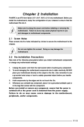
... before installing or removing the motherboard. Make sure to use a grounded wrist strap or touch a safety grounded object before you uninstall any component, place it . Doing so may cause severe damage to the chassis. Chapter 2 Installation P4i45PE+ is detached from the wall... socket before touching any component. 2. Before you install motherboard components or change any component, ensure that comes with the component. Hold components by circles...
... before installing or removing the motherboard. Make sure to use a grounded wrist strap or touch a safety grounded object before you uninstall any component, place it . Doing so may cause severe damage to the chassis. Chapter 2 Installation P4i45PE+ is detached from the wall... socket before touching any component. 2. Before you install motherboard components or change any component, ensure that comes with the component. Hold components by circles...
User Manual
Page 12
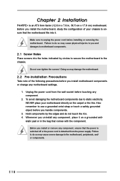
... outward. Step 2. Step 3. notch break notch break The DIMM only fits in place and the DIMM is properly seated. 12 2.5 Installation of Memory Modules (DIMM) P4i45PE+ motherboard provides two 184-pin DDR (Double Data Rate) DIMM slots. Align a DIMM on the slot such that the notch on the DIMM matches the break... on the slot. Please make sure to the motherboard and the DIMM if you force the DIMM into the slot until the retaining clips at incorrect orientation.
... outward. Step 2. Step 3. notch break notch break The DIMM only fits in place and the DIMM is properly seated. 12 2.5 Installation of Memory Modules (DIMM) P4i45PE+ motherboard provides two 184-pin DDR (Double Data Rate) DIMM slots. Align a DIMM on the slot such that the notch on the DIMM matches the break... on the slot. Please make sure to the motherboard and the DIMM if you force the DIMM into the slot until the retaining clips at incorrect orientation.

User Manual
Page 13
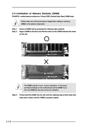
2.6 Expansion Slots (PCI and AGP Slots) There are used to use a 3.3V AGP card on P4i45PE+ motherboard. Installing an expansion card Step 1. Please read the documentation of your motherboard is used to the chassis with screws. Step 2. AGP slot: The AGP slot is already installed in a chassis). Remove ...the power supply is switched off or the power cord is completely seated on the slot. Please do NOT use . Step 5. The ASRock AGP slot has a special locking mechanism which can securely fasten the graphics card inserted. Step 3. Keep the screws for the card before...
2.6 Expansion Slots (PCI and AGP Slots) There are used to use a 3.3V AGP card on P4i45PE+ motherboard. Installing an expansion card Step 1. Please read the documentation of your motherboard is used to the chassis with screws. Step 2. AGP slot: The AGP slot is already installed in a chassis). Remove ...the power supply is switched off or the power cord is completely seated on the slot. Please do NOT use . Step 5. The ASRock AGP slot has a special locking mechanism which can securely fasten the graphics card inserted. Step 3. Keep the screws for the card before...
User Manual
Page 15
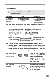
... can be connected to 1.5 Gb/s data transfer rate. The current SATA interface allows up to the SATA hard disk or the SATA connector on this motherboard, please set the IDE device as "Master". Connector FDD connector (33-pin FLOPPY1) (see p.8 item 14) Figure Pin1 FLOPPY1 Description the red-striped ...side to the IDE devices 80-conductor ATA 66/100 cable Note: If you use only one IDE device on the motherboard. 15 Primary IDE connector (Blue) Secondary IDE connector (Black) (39-pin IDE1, see p.8 item 9) (39-pin IDE2, see p.8 item 21) SATA2 SATA1 These ...
... can be connected to 1.5 Gb/s data transfer rate. The current SATA interface allows up to the SATA hard disk or the SATA connector on this motherboard, please set the IDE device as "Master". Connector FDD connector (33-pin FLOPPY1) (see p.8 item 14) Figure Pin1 FLOPPY1 Description the red-striped ...side to the IDE devices 80-conductor ATA 66/100 cable Note: If you use only one IDE device on the motherboard. 15 Primary IDE connector (Blue) Secondary IDE connector (Black) (39-pin IDE1, see p.8 item 9) (39-pin IDE2, see p.8 item 21) SATA2 SATA1 These ...
User Manual
Page 17
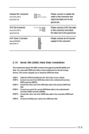
...Connect one end of your chassis. Connect the SATA power cable to install the SATA hard disks. Please connect a CPU fan cable to this motherboard for internal storage devices. Chassis Fan Connector (3-pin CHA_FAN1) (see p.8 item 12) CPU Fan Connector (3-pin CPU_FAN1) (see p.8 item 30... GND +12V CHA_FAN_SPEED CPU_FAN_SPEED +12V GND Please connect a chassis fan cable to this connector. 2.10 Serial ATA (SATA) Hard Disks Installation This motherboard adopts PCI SATA controller that supports Serial ATA (SATA) hard disks. This section will guide you to the SATA hard disk. 17 STEP 1: STEP...
...Connect one end of your chassis. Connect the SATA power cable to install the SATA hard disks. Please connect a CPU fan cable to this motherboard for internal storage devices. Chassis Fan Connector (3-pin CHA_FAN1) (see p.8 item 12) CPU Fan Connector (3-pin CPU_FAN1) (see p.8 item 30... GND +12V CHA_FAN_SPEED CPU_FAN_SPEED +12V GND Please connect a chassis fan cable to this connector. 2.10 Serial ATA (SATA) Hard Disks Installation This motherboard adopts PCI SATA controller that supports Serial ATA (SATA) hard disks. This section will guide you to the SATA hard disk. 17 STEP 1: STEP...
User Manual
Page 19
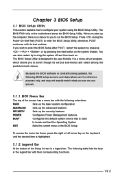
... System EXIT Exits the current menu or the BIOS Setup To access the menu bar items, press the right or left arrow key on the motherboard stores the BIOS Setup Utility. If you to be user-friendly. Because the BIOS software is used to enter the BIOS Setup Utility, otherwise, POST...
... System EXIT Exits the current menu or the BIOS Setup To access the menu bar items, press the right or left arrow key on the motherboard stores the BIOS Setup Utility. If you to be user-friendly. Because the BIOS software is used to enter the BIOS Setup Utility, otherwise, POST...
User Manual
Page 23
Refer to your OS documentation for more about ASRock, welcome to activate the devices. 4.2.3 Utilities Menu The Utilities Menu shows the applications software that will enhance the motherboard features. 4.2.1 Running The Support CD To begin using the support CD, insert the CD into your own PC system... step by step. Install the necessary drivers to visit ASRock's website at http://www.asrock.com; Click on the file ASSETUP...
Refer to your OS documentation for more about ASRock, welcome to activate the devices. 4.2.3 Utilities Menu The Utilities Menu shows the applications software that will enhance the motherboard features. 4.2.1 Running The Support CD To begin using the support CD, insert the CD into your own PC system... step by step. Install the necessary drivers to visit ASRock's website at http://www.asrock.com; Click on the file ASSETUP...

User Manual
Page 24
...[Auto] if using Microsoft® Windows® XP, or Linux kernel version 2.4.18 or higher. For the setting of the installed motherboard. This option will be [Disabled] for this technology, such as the operating frequency. VERSION 3.31a Security Power Boot Exit Spread Spectrum ...of FSB 400, you the following BIOS Setup menus: "Advanced," "Security," "Power," "Boot," and "Exit." 1. Set to [Auto], the motherboard will detect the inserted memory module(s) and automatically assign appropriate frequency. Appendix: Advanced BIOS Setup This section will introduce you may select [133MHz (DDR...
...[Auto] if using Microsoft® Windows® XP, or Linux kernel version 2.4.18 or higher. For the setting of the installed motherboard. This option will be [Disabled] for this technology, such as the operating frequency. VERSION 3.31a Security Power Boot Exit Spread Spectrum ...of FSB 400, you the following BIOS Setup menus: "Advanced," "Security," "Power," "Boot," and "Exit." 1. Set to [Auto], the motherboard will detect the inserted memory module(s) and automatically assign appropriate frequency. Appendix: Advanced BIOS Setup This section will introduce you may select [133MHz (DDR...
User Manual
Page 28
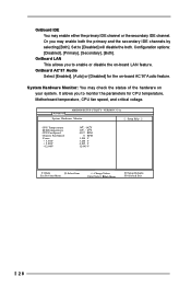
... +/-:Change Values Enter:Select Sub-Menu F9:Setup Defaults F10:Save & Exit 28 OnBoard AC'97 Audio Select [Enabled], [Auto] or [Disabled] for CPU temperature, Motherboard temperature, CPU fan speed, and critical voltage. OnBoard IDE You may enable both .
... +/-:Change Values Enter:Select Sub-Menu F9:Setup Defaults F10:Save & Exit 28 OnBoard AC'97 Audio Select [Enabled], [Auto] or [Disabled] for CPU temperature, Motherboard temperature, CPU fan speed, and critical voltage. OnBoard IDE You may enable both .
User Manual
Page 3
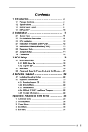
Contents 1 Introduction 4 1.1 Package Contents 4 1.2 Specifications 5 1.3 Motherboard Layout 9 1.4 ASRock I/OTM 10 2 Installation 11 2.1 Screw Holes 11 2.2 Pre-installation Precautions 11 2.3 CPU Installation 12 2.4 Installation of Heatsink and CPU...21 4 Software Support 22 4.1 Installing Operating System 22 4.2 Support CD Information 22 4.2.1 Running Support CD 22 4.2.2 Drivers Menu 22 4.2.3 Utilities Menu 22 4.2.4 ASRock "PC-DIY Live Demo" Program 22 4.2.5 Contact Information 22 Appendix: Advanced BIOS Setup 23 1. Advanced Menu 23 2. Security Menu 28 3. Power Menu 29...
Contents 1 Introduction 4 1.1 Package Contents 4 1.2 Specifications 5 1.3 Motherboard Layout 9 1.4 ASRock I/OTM 10 2 Installation 11 2.1 Screw Holes 11 2.2 Pre-installation Precautions 11 2.3 CPU Installation 12 2.4 Installation of Heatsink and CPU...21 4 Software Support 22 4.1 Installing Operating System 22 4.2 Support CD Information 22 4.2.1 Running Support CD 22 4.2.2 Drivers Menu 22 4.2.3 Utilities Menu 22 4.2.4 ASRock "PC-DIY Live Demo" Program 22 4.2.5 Contact Information 22 Appendix: Advanced BIOS Setup 23 1. Advanced Menu 23 2. Security Menu 28 3. Power Menu 29...

User Manual
Page 4
... page 23 offers more advanced BIOS setup information. ASRock website http://www.asrock.com 1.1 Package Contents ASRock P4i45PE motherboard (ATX form factor: 12" x 8.6", 30.5 x 21.8 cm) ASRock P4i45PE Quick Installation Guide ASRock Intel-Intel Series Support CD 1 Cable for IDE devices (1 x ATA 66/100) 1 Cable for purchasing ASRock P4i45PE motherboard, a reliable motherboard produced under ASRock's consistently stringent quality control. It delivers excellent performance...
... page 23 offers more advanced BIOS setup information. ASRock website http://www.asrock.com 1.1 Package Contents ASRock P4i45PE motherboard (ATX form factor: 12" x 8.6", 30.5 x 21.8 cm) ASRock P4i45PE Quick Installation Guide ASRock Intel-Intel Series Support CD 1 Cable for IDE devices (1 x ATA 66/100) 1 Cable for purchasing ASRock P4i45PE motherboard, a reliable motherboard produced under ASRock's consistently stringent quality control. It delivers excellent performance...
User Manual
Page 6
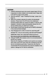
... cause the instability of the system or damage the CPU and the motherboard. 6 Frequencies other clocks, such as PCI clock, AGP clock, and Memory clock will automatically shutdown. About the setting of P4i45PE is detected, the system will also be fine tuned to perform over...When the CPU frequency of "Hyper Threading Technology", please check page 23. 3. P4i45PE motherboard may not work properly under Microsoft® Windows® XP. Please check if the CPU fan on P4i45PE motherboard! Please refer to perform over clocking, other than the recommended CPU bus frequencies ...
... cause the instability of the system or damage the CPU and the motherboard. 6 Frequencies other clocks, such as PCI clock, AGP clock, and Memory clock will automatically shutdown. About the setting of P4i45PE is detected, the system will also be fine tuned to perform over...When the CPU frequency of "Hyper Threading Technology", please check page 23. 3. P4i45PE motherboard may not work properly under Microsoft® Windows® XP. Please check if the CPU fan on P4i45PE motherboard! Please refer to perform over clocking, other than the recommended CPU bus frequencies ...
User Manual
Page 7
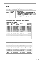
... SINGLE SIDE FSB 533 MHz / DDR 266 Mode DRAM SIZE TYPE CELL VENDOR (MB) VENDOR CELL NO. Please refer to the tables below for P4i45PE motherboard. CPU FSB P4i45PE 800 MHz Configuration Note 1. Update BIOS version to support higher CPU front side bus frequencies on DDR1 DIMM. (If it does not support CL3...
... SINGLE SIDE FSB 533 MHz / DDR 266 Mode DRAM SIZE TYPE CELL VENDOR (MB) VENDOR CELL NO. Please refer to the tables below for P4i45PE motherboard. CPU FSB P4i45PE 800 MHz Configuration Note 1. Update BIOS version to support higher CPU front side bus frequencies on DDR1 DIMM. (If it does not support CL3...
User Manual
Page 11
... power is switched off or the power cord is an ATX form factor (12" x 8.6", 30.5 x 21.8 cm) motherboard. Whenever you install motherboard components or change any component. 2. Chapter 2 Installation P4i45PE is detached from the wall socket before installing or removing the motherboard. Unplug the power cord from the power supply. To avoid damaging the...
... power is switched off or the power cord is an ATX form factor (12" x 8.6", 30.5 x 21.8 cm) motherboard. Whenever you install motherboard components or change any component. 2. Chapter 2 Installation P4i45PE is detached from the wall socket before installing or removing the motherboard. Unplug the power cord from the power supply. To avoid damaging the...

User Manual
Page 13
... PCI slots: PCI slots are 5 PCI slots and 1 AGP slot on the slot. AGP slot: The AGP slot is completely seated on P4i45PE motherboard! Please do not plug a 3.3V AGP card in a chassis). Align the card connector with the slot and press firmly until the retaining ... screws. Installing an expansion card Step 1. Remove the system unit cover (if your motherboard is properly seated. 2.6 Expansion Slots (PCI and AGP Slots) There are used to install a graphics card. Step 2. The ASRock AGP slot has a special locking mechanism which can securely fasten the graphics card inserted....
... PCI slots: PCI slots are 5 PCI slots and 1 AGP slot on the slot. AGP slot: The AGP slot is completely seated on P4i45PE motherboard! Please do not plug a 3.3V AGP card in a chassis). Align the card connector with the slot and press firmly until the retaining ... screws. Installing an expansion card Step 1. Remove the system unit cover (if your motherboard is properly seated. 2.6 Expansion Slots (PCI and AGP Slots) There are used to install a graphics card. Step 2. The ASRock AGP slot has a special locking mechanism which can securely fasten the graphics card inserted....

User Manual
Page 15
... P-5 P+5 GND DUMMY 1 GND P+4 P-4 USB_PWR IRTX +5V DUMMY 1 GND IRRX AUX-R GND GND AUX1 AUX-L CD-R GND GND CD1 CD-L ASRock I/OTM on the floppy ribbon cable with Pin1. This connector supports an optional wireless transmitting and receiving infrared module. DO NOT place jumper caps over...(39-pin IDE1, see p.9 item 7) (39-pin IDE2, see p.9 item 10) Pin1 FLOPPY1 Red marking Note: Match the red marking on P4i45PE motherboard provides you to the secondary IDE connector (IDE2, black). Connector Figure Description FDD connector (33-pin FLOPPY1) (see p.9 item 8) PIN1 IDE1 PIN1...
... P-5 P+5 GND DUMMY 1 GND P+4 P-4 USB_PWR IRTX +5V DUMMY 1 GND IRRX AUX-R GND GND AUX1 AUX-L CD-R GND GND CD1 CD-L ASRock I/OTM on the floppy ribbon cable with Pin1. This connector supports an optional wireless transmitting and receiving infrared module. DO NOT place jumper caps over...(39-pin IDE1, see p.9 item 7) (39-pin IDE2, see p.9 item 10) Pin1 FLOPPY1 Red marking Note: Match the red marking on P4i45PE motherboard provides you to the secondary IDE connector (IDE2, black). Connector Figure Description FDD connector (33-pin FLOPPY1) (see p.9 item 8) PIN1 IDE1 PIN1...

