
User Manual
Page 5
... 41 Chapter 3 Software and Utilities Operation 45 3.1 Installing Drivers 45 3.2 A-Tuning 46 3.2.1 Installing A-Tuning 46 3.2.2 Using A-Tuning 46 3.3 ASRock Live Update & APP Shop 49 3.3.1 UI Overview 49 3.3.2 Apps 50 3.3.3 BIOS & Drivers 53 3.3.4 Setting 54 3.4 ASRock RGB LED 55 Chapter 4 UEFI SETUP UTILITY 57 4.1 Introduction 57 4.2 EZ Mode 58 4.3 Advanced Mode 59 4.3.1 UEFI Menu...
... 41 Chapter 3 Software and Utilities Operation 45 3.1 Installing Drivers 45 3.2 A-Tuning 46 3.2.1 Installing A-Tuning 46 3.2.2 Using A-Tuning 46 3.3 ASRock Live Update & APP Shop 49 3.3.1 UI Overview 49 3.3.2 Apps 50 3.3.3 BIOS & Drivers 53 3.3.4 Setting 54 3.4 ASRock RGB LED 55 Chapter 4 UEFI SETUP UTILITY 57 4.1 Introduction 57 4.2 EZ Mode 58 4.3 Advanced Mode 59 4.3.1 UEFI Menu...
User Manual
Page 7
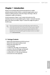
... find the latest VGA cards and CPU support list on ASRock's website without notice. Because the motherboard specifications and the BIOS software might be available on ASRock's website as well. In case any modifications of this documentation will be updated, the content of the BIOS setup. X299 Taichi Chapter 1 Introduction Thank you for M.2 Sockets (Optional) 1 English...
... find the latest VGA cards and CPU support list on ASRock's website without notice. Because the motherboard specifications and the BIOS software might be available on ASRock's website as well. In case any modifications of this documentation will be updated, the content of the BIOS setup. X299 Taichi Chapter 1 Introduction Thank you for M.2 Sockets (Optional) 1 English...

User Manual
Page 10
...Keyboard Port • 1 x Optical SPDIF Out Port • 2 x USB 2.0 Ports (Supports ESD Protection (ASRock Full Spike Protection)) • 1 x USB 3.1 Type-A Port (10 Gb/s) (ASMedia ASM3142) (Supports ESD Protection (ASRock Full Spike Protection)) • 1 x USB 3.1 Type-C Port (10 Gb/s) (ASMedia ASM3142) (Supports ESD ... supported on USB3_12 ports. • 4 x USB 3.0 Ports (Supports ESD Protection (ASRock Full Spike Protection)) • 2 x RJ-45 LAN Ports with LED (ACT/LINK LED and SPEED LED) • 1 x BIOS Flashback Switch • 1 x Clear CMOS Switch • HD Audio Jacks: Rear ...
...Keyboard Port • 1 x Optical SPDIF Out Port • 2 x USB 2.0 Ports (Supports ESD Protection (ASRock Full Spike Protection)) • 1 x USB 3.1 Type-A Port (10 Gb/s) (ASMedia ASM3142) (Supports ESD Protection (ASRock Full Spike Protection)) • 1 x USB 3.1 Type-C Port (10 Gb/s) (ASMedia ASM3142) (Supports ESD ... supported on USB3_12 ports. • 4 x USB 3.0 Ports (Supports ESD Protection (ASRock Full Spike Protection)) • 2 x RJ-45 LAN Ports with LED (ACT/LINK LED and SPEED LED) • 1 x BIOS Flashback Switch • 1 x Clear CMOS Switch • HD Audio Jacks: Rear ...

User Manual
Page 12
... our website: http://www.asrock.com Please realize that there is a certain risk involved with overclocking, including adjusting the setting in the BIOS, applying Untied Overclocking Technology, or using third-party overclocking tools. BIOS Feature Hardware Monitor OS Certifications • 2 x AMI UEFI Legal BIOS with multilingual GUI support (1 x Main BIOS and 1 x Backup BIOS) • Supports Secure...
... our website: http://www.asrock.com Please realize that there is a certain risk involved with overclocking, including adjusting the setting in the BIOS, applying Untied Overclocking Technology, or using third-party overclocking tools. BIOS Feature Hardware Monitor OS Certifications • 2 x AMI UEFI Legal BIOS with multilingual GUI support (1 x Main BIOS and 1 x Backup BIOS) • Supports Secure...

User Manual
Page 13
1.3 Motherboard Layout X299 Taichi 12 3 456 7 USB 2.0 T: USB1 B: USB2 PS2 Keyboard /Mouse CLRC BTN1 M2_WIFI_1 BIOS _FB1 USB 3.0 T: USB1 Top: RJ-45 B: USB2 LAN USB 3.0 T: USB3 B: USB4 ATX12V1 CPU_OPT/W_PUMP 2066 Socket CPU_FAN1 1 8 RGB_LED2 9 ATXPWR1 ...Central/Bass LINE IN Center: REAR SPK Bottom: Optical SPDIF Top: Center: FRONT Bottom: MIC IN 30 LAN CHA_FAN2 PCIE1 X299 Taichi PCIE2 M2_2 M2_1 1 VROC1 Intel X299 SATA3_2_3 SATA3_0_1 USB3_5_6 USB31_TC_2 USB3_7_8 10 11 1 12 1 13 14 15 16 SATA3_4_5 SATA3_A1_A2 SATA3_6_7 PCIE3 Purity SoundTM 4 PCIE4 HD_AUDIO1...
1.3 Motherboard Layout X299 Taichi 12 3 456 7 USB 2.0 T: USB1 B: USB2 PS2 Keyboard /Mouse CLRC BTN1 M2_WIFI_1 BIOS _FB1 USB 3.0 T: USB1 Top: RJ-45 B: USB2 LAN USB 3.0 T: USB3 B: USB4 ATX12V1 CPU_OPT/W_PUMP 2066 Socket CPU_FAN1 1 8 RGB_LED2 9 ATXPWR1 ...Central/Bass LINE IN Center: REAR SPK Bottom: Optical SPDIF Top: Center: FRONT Bottom: MIC IN 30 LAN CHA_FAN2 PCIE1 X299 Taichi PCIE2 M2_2 M2_1 1 VROC1 Intel X299 SATA3_2_3 SATA3_0_1 USB3_5_6 USB31_TC_2 USB3_7_8 10 11 1 12 1 13 14 15 16 SATA3_4_5 SATA3_A1_A2 SATA3_6_7 PCIE3 Purity SoundTM 4 PCIE4 HD_AUDIO1...

User Manual
Page 28
... will be cleared only if the CMOS battery is "Short". Clear CMOS Jumper (CLRMOS1) (see p.7, No. 28) Default Clear CMOS CLRMOS1 allows you update the BIOS. English 22 2.5 Jumpers Setup The illustration shows how jumpers are "Short" when a jumper cap is placed on the pins, the jumper is placed on CLRMOS1... in CMOS. When the jumper cap is "Open". To clear and reset the system parameters to clear the CMOS when you just finish updating the BIOS, you must boot up the system first, and then shut it down before you do not clear the CMOS right after you to short pin2...
... will be cleared only if the CMOS battery is "Short". Clear CMOS Jumper (CLRMOS1) (see p.7, No. 28) Default Clear CMOS CLRMOS1 allows you update the BIOS. English 22 2.5 Jumpers Setup The illustration shows how jumpers are "Short" when a jumper cap is placed on the pins, the jumper is placed on CLRMOS1... in CMOS. When the jumper cap is "Open". To clear and reset the system parameters to clear the CMOS when you just finish updating the BIOS, you must boot up the system first, and then shut it down before you do not clear the CMOS right after you to short pin2...

User Manual
Page 35
... users to the USB BIOS Flashback port. 4. Download the latest BIOS file from ASRock's website : http://www.asrock.com. 2. Please follow the steps below. 1. Wait until the LED stops blinking, indicating that BIOS flashing has been completed. *If the LED light turns solid green, this means that the CPU is not installed; X299 Taichi 2.7 Smart Switches The...
... users to the USB BIOS Flashback port. 4. Download the latest BIOS file from ASRock's website : http://www.asrock.com. 2. Please follow the steps below. 1. Wait until the LED stops blinking, indicating that BIOS flashing has been completed. *If the LED light turns solid green, this means that the CPU is not installed; X299 Taichi 2.7 Smart Switches The...

User Manual
Page 59
X299 Taichi 3.3.3 BIOS & Drivers Installing BIOS or Drivers When the "BIOS & Drivers" tab is selected, you will see more items you want to start the update process. 53 English Click to select one or more details. Step 3 Click Update to update. Step 1 Please check the item information before update. Please update them all soon. Click on Step 2 to see a list of recommended or critical updates for the BIOS or drivers.
X299 Taichi 3.3.3 BIOS & Drivers Installing BIOS or Drivers When the "BIOS & Drivers" tab is selected, you will see more items you want to start the update process. 53 English Click to select one or more details. Step 3 Click Update to update. Step 1 Please check the item information before update. Please update them all soon. Click on Step 2 to see a list of recommended or critical updates for the BIOS or drivers.

User Manual
Page 64
You can check the most crucial information of the screen to switch to Advanced Mode 58 English No. 4.2 EZ Mode The EZ Mode screen appears when you enter the BIOS setup program by default. Press or click the "Advanced Mode" button at the upper right corner of your system, such as CPU speed, DRAM frequency, SATA information, fan speed, etc. Function 1 Help 2 Load UEFI Defaults 3 Save Changes and Exit 4 Discard Changes 5 Change Language 6 Switch to "Advanced Mode" for more options. EZ mode is a dashboard which contains multiple readings of the system's current status.
You can check the most crucial information of the screen to switch to Advanced Mode 58 English No. 4.2 EZ Mode The EZ Mode screen appears when you enter the BIOS setup program by default. Press or click the "Advanced Mode" button at the upper right corner of your system, such as CPU speed, DRAM frequency, SATA information, fan speed, etc. Function 1 Help 2 Load UEFI Defaults 3 Save Changes and Exit 4 Discard Changes 5 Change Language 6 Switch to "Advanced Mode" for more options. EZ mode is a dashboard which contains multiple readings of the system's current status.

User Manual
Page 65
... upper right corner of the screen. 4.3.1 UEFI Menu Bar The top of the screen has a menu bar with the following sections for the detailed configurations. X299 Taichi 4.3 Advanced Mode The Advanced Mode provides more options to the following selections: Main For setting system time/date information OC Tweaker For overclocking configurations Advanced... boot settings and boot priority Security For security settings Exit Exit the current screen or the UEFI Setup Utility English 59 Refer to configure the BIOS settings.
... upper right corner of the screen. 4.3.1 UEFI Menu Bar The top of the screen has a menu bar with the following sections for the detailed configurations. X299 Taichi 4.3 Advanced Mode The Advanced Mode provides more options to the following selections: Main For setting system time/date information OC Tweaker For overclocking configurations Advanced... boot settings and boot priority Security For security settings Exit Exit the current screen or the UEFI Setup Utility English 59 Refer to configure the BIOS settings.

User Manual
Page 67
X299 Taichi 4.4 Main Screen When you enter the UEFI SETUP UTILITY, the Main screen will appear and display the system overview. Favorite Display your collection of BIOS items. Press F5 to add/remove your favorite items. 61 English
X299 Taichi 4.4 Main Screen When you enter the UEFI SETUP UTILITY, the Main screen will appear and display the system overview. Favorite Display your collection of BIOS items. Press F5 to add/remove your favorite items. 61 English

User Manual
Page 71
ClockGen Delay Configure the delay at the beginning of Clockgen. Boot Performance Mode Select the performance state that the BIOS will expose the CPPC v2 interface to allow for higher -BCLK ration combination. 65 English FCLK Frequency Configure the FCLK Frequency. Intel ...or PCIE PLL as the CPU2/SRC1 source. Enabling will set before OS handoff. Adjust Pll Adjust the Pll for hardware controlled P-states. X299 Taichi SRC Output Divider Configure the SRC output divider. PCIE PLL Divider Configure the PCIE PLL divider. MFC Mode Override Configure the MFC Mode Override.
ClockGen Delay Configure the delay at the beginning of Clockgen. Boot Performance Mode Select the performance state that the BIOS will expose the CPPC v2 interface to allow for higher -BCLK ration combination. 65 English FCLK Frequency Configure the FCLK Frequency. Intel ...or PCIE PLL as the CPU2/SRC1 source. Enabling will set before OS handoff. Adjust Pll Adjust the Pll for hardware controlled P-states. X299 Taichi SRC Output Divider Configure the SRC output divider. PCIE PLL Divider Configure the PCIE PLL divider. MFC Mode Override Configure the MFC Mode Override.

User Manual
Page 87
... providing additional levels of manageability, security, isolation, and I/O performance. PCIE1 Link Speed Select the link speed for PCIE2. 4.6.2 Chipset Configuration X299 Taichi Above 4GB MMIO BIOS Assignment Enable/disable above 4GB MemoryMappedIO BIOS assignment. PCIE2 Link Speed Select the link speed for PCIE1. PCIE3 Link Speed Select the link speed for PCIE3. This is...
... providing additional levels of manageability, security, isolation, and I/O performance. PCIE1 Link Speed Select the link speed for PCIE2. 4.6.2 Chipset Configuration X299 Taichi Above 4GB MMIO BIOS Assignment Enable/disable above 4GB MemoryMappedIO BIOS assignment. PCIE2 Link Speed Select the link speed for PCIE1. PCIE3 Link Speed Select the link speed for PCIE3. This is...

User Manual
Page 96
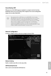
After copying the drivers please change the SATA mode to update your PC. Please setup network configuration before using Internet Flash. *For BIOS backup and recovery purpose, it is recommended to your USB pen drive before using this function. 90 English Easy RAID Installer Easy RAID ... device and run Instant Flash to RAID, then you can start installing the operating system in your USB storage device. DHCP (Auto IP), Auto ASRock Internet Flash downloads and updates the latest UEFI firmware version from the support CD to plug in RAID mode. Internet Flash - 4.7 Tools UEFI Tech...
After copying the drivers please change the SATA mode to update your PC. Please setup network configuration before using Internet Flash. *For BIOS backup and recovery purpose, it is recommended to your USB pen drive before using this function. 90 English Easy RAID Installer Easy RAID ... device and run Instant Flash to RAID, then you can start installing the operating system in your USB storage device. DHCP (Auto IP), Auto ASRock Internet Flash downloads and updates the latest UEFI firmware version from the support CD to plug in RAID mode. Internet Flash - 4.7 Tools UEFI Tech...
User Manual
Page 97
... image to the secondary flash ROM. Network Configuration Use this to download the UEFI firmware. 91 English X299 Taichi Secure Backup UEFI Whenever one of the ROM images are not able to update the backup BIOS manually. For safety issues, users are outdated or corrupted, switch to the other flash ROM and execute...
... image to the secondary flash ROM. Network Configuration Use this to download the UEFI firmware. 91 English X299 Taichi Secure Backup UEFI Whenever one of the ROM images are not able to update the backup BIOS manually. For safety issues, users are outdated or corrupted, switch to the other flash ROM and execute...

Quick Installation Guide
Page 3
Motherboard Layout 12 X299 Taichi 3 456 7 USB 2.0 T: USB1 B: USB2 PS2 Keyboard /Mouse CLRC BTN1 M2_WIFI_1 BIOS _FB1 USB 3.0 T: USB1 Top: RJ-45 B: USB2 LAN USB 3.0 T: USB3 B: USB4 ATX12V1 CPU_OPT/W_PUMP 2066 Socket CPU_FAN1 1 8 RGB_LED2 9 ATXPWR1 DDR4_C2 ...Central/Bass LINE IN Center: REAR SPK Bottom: Optical SPDIF Top: Center: FRONT Bottom: MIC IN 30 LAN CHA_FAN2 PCIE1 X299 Taichi PCIE2 M2_2 M2_1 1 VROC1 Intel X299 SATA3_2_3 SATA3_0_1 USB3_5_6 USB31_TC_2 USB3_7_8 10 11 1 12 1 13 14 15 16 SATA3_4_5 SATA3_A1_A2 SATA3_6_7 PCIE3 Purity SoundTM 4 PCIE4 HD_AUDIO1...
Motherboard Layout 12 X299 Taichi 3 456 7 USB 2.0 T: USB1 B: USB2 PS2 Keyboard /Mouse CLRC BTN1 M2_WIFI_1 BIOS _FB1 USB 3.0 T: USB1 Top: RJ-45 B: USB2 LAN USB 3.0 T: USB3 B: USB4 ATX12V1 CPU_OPT/W_PUMP 2066 Socket CPU_FAN1 1 8 RGB_LED2 9 ATXPWR1 DDR4_C2 ...Central/Bass LINE IN Center: REAR SPK Bottom: Optical SPDIF Top: Center: FRONT Bottom: MIC IN 30 LAN CHA_FAN2 PCIE1 X299 Taichi PCIE2 M2_2 M2_1 1 VROC1 Intel X299 SATA3_2_3 SATA3_0_1 USB3_5_6 USB31_TC_2 USB3_7_8 10 11 1 12 1 13 14 15 16 SATA3_4_5 SATA3_A1_A2 SATA3_6_7 PCIE3 Purity SoundTM 4 PCIE4 HD_AUDIO1...

Quick Installation Guide
Page 7
... Antennas (Optional) • 3 x Screws for purchasing ASRock X299 Taichi motherboard, a reliable motherboard produced under ASRock's consistently stringent quality control. If you require technical support related to this documentation will be subject to quality and endurance. X299 Taichi Chapter 1 Introduction Thank you are using. Because the motherboard specifications and the BIOS software might be updated, the content of...
... Antennas (Optional) • 3 x Screws for purchasing ASRock X299 Taichi motherboard, a reliable motherboard produced under ASRock's consistently stringent quality control. If you require technical support related to this documentation will be subject to quality and endurance. X299 Taichi Chapter 1 Introduction Thank you are using. Because the motherboard specifications and the BIOS software might be updated, the content of...

Quick Installation Guide
Page 10
...supported on USB3_12 ports. • 4 x USB 3.0 Ports (Supports ESD Protection (ASRock Full Spike Protection)) • 2 x RJ-45 LAN Ports with LED (ACT/LINK LED and SPEED LED) • 1 x BIOS Flashback Switch • 1 x Clear CMOS Switch • HD Audio Jacks: .../Keyboard Port • 1 x Optical SPDIF Out Port • 2 x USB 2.0 Ports (Supports ESD Protection (ASRock Full Spike Protection)) • 1 x USB 3.1 Type-A Port (10 Gb/s) (ASMedia ASM3142) (Supports ESD Protection (ASRock Full Spike Protection)) • 1 x USB 3.1 Type-C Port (10 Gb/s) (ASMedia ASM3142) (Supports ESD Protection...
...supported on USB3_12 ports. • 4 x USB 3.0 Ports (Supports ESD Protection (ASRock Full Spike Protection)) • 2 x RJ-45 LAN Ports with LED (ACT/LINK LED and SPEED LED) • 1 x BIOS Flashback Switch • 1 x Clear CMOS Switch • HD Audio Jacks: .../Keyboard Port • 1 x Optical SPDIF Out Port • 2 x USB 2.0 Ports (Supports ESD Protection (ASRock Full Spike Protection)) • 1 x USB 3.1 Type-A Port (10 Gb/s) (ASMedia ASM3142) (Supports ESD Protection (ASRock Full Spike Protection)) • 1 x USB 3.1 Type-C Port (10 Gb/s) (ASMedia ASM3142) (Supports ESD Protection...

Quick Installation Guide
Page 12
... is required) * For detailed product information, please visit our website: http://www.asrock.com Please realize that there is a certain risk involved with multilingual GUI support (1 x Main BIOS and 1 x Backup BIOS) • Supports Secure Backup UEFI Technology • ACPI 6.1 Compliant wake up ...fan speed by overclocking. It should be done at your system. BIOS Feature Hardware Monitor OS Certifications • 2 x AMI UEFI Legal BIOS with overclocking, including adjusting the setting in the BIOS, applying Untied Overclocking Technology, or using third-party overclocking tools. ...
... is required) * For detailed product information, please visit our website: http://www.asrock.com Please realize that there is a certain risk involved with multilingual GUI support (1 x Main BIOS and 1 x Backup BIOS) • Supports Secure Backup UEFI Technology • ACPI 6.1 Compliant wake up ...fan speed by overclocking. It should be done at your system. BIOS Feature Hardware Monitor OS Certifications • 2 x AMI UEFI Legal BIOS with overclocking, including adjusting the setting in the BIOS, applying Untied Overclocking Technology, or using third-party overclocking tools. ...

Quick Installation Guide
Page 24
Clear CMOS Jumper (CLRMOS1) (see p.1, No. 28) Default Clear CMOS CLRMOS1 allows you update the BIOS. However, please do the clear-CMOS action. Please be noted that the password, date, time, and user default profile will be cleared only if the ... to short pin2 and pin3 on the pins, the jumper is "Short". If you need to clear the CMOS when you just finish updating the BIOS, you must boot up the system first, and then shut it down before you do not clear the CMOS right after you to default setup...
Clear CMOS Jumper (CLRMOS1) (see p.1, No. 28) Default Clear CMOS CLRMOS1 allows you update the BIOS. However, please do the clear-CMOS action. Please be noted that the password, date, time, and user default profile will be cleared only if the ... to short pin2 and pin3 on the pins, the jumper is "Short". If you need to clear the CMOS when you just finish updating the BIOS, you must boot up the system first, and then shut it down before you do not clear the CMOS right after you to default setup...


