
User Manual
Page 5
3.2 A-Tuning 45 3.2.1 Installing A-Tuning 45 3.2.2 Using A-Tuning 45 3.3 ASRock Live Update & APP Shop 48 3.3.1 UI Overview 48 3.3.2 Apps 49 3.3.3 BIOS & Drivers 52 3.3.4 Setting 53 3.4 ASRock RGB LED 54 Chapter 4 UEFI SETUP UTILITY 56 4.1 Introduction 56 4.1.1 UEFI Menu Bar 56 4.1.2 Navigation Keys 57 4.2 Main Screen 58 4.3 OC Tweaker Screen 59 4.4 Advanced ...
3.2 A-Tuning 45 3.2.1 Installing A-Tuning 45 3.2.2 Using A-Tuning 45 3.3 ASRock Live Update & APP Shop 48 3.3.1 UI Overview 48 3.3.2 Apps 49 3.3.3 BIOS & Drivers 52 3.3.4 Setting 53 3.4 ASRock RGB LED 54 Chapter 4 UEFI SETUP UTILITY 56 4.1 Introduction 56 4.1.1 UEFI Menu Bar 56 4.1.2 Navigation Keys 57 4.2 Main Screen 58 4.3 OC Tweaker Screen 59 4.4 Advanced ...

User Manual
Page 7
... Card (Optional) • 3 x Screws for M.2 Socket (Optional) (for X370 Killer SLI only) • 2 x Screws for M.2 Socket (Optional) (for X370 Killer SLI/ac only) • 2 x ASRock WiFi 2.4/5 GHz Antennas (Optional) (for purchasing ASRock X370 Killer SLI/ac / X370 Killer SLI motherboard, a reliable motherboard produced under ASRock's consistently stringent quality control. Chapter 3 contains the operation guide of the BIOS setup. In case any modifications of this documentation occur...
... Card (Optional) • 3 x Screws for M.2 Socket (Optional) (for X370 Killer SLI only) • 2 x Screws for M.2 Socket (Optional) (for X370 Killer SLI/ac only) • 2 x ASRock WiFi 2.4/5 GHz Antennas (Optional) (for purchasing ASRock X370 Killer SLI/ac / X370 Killer SLI motherboard, a reliable motherboard produced under ASRock's consistently stringent quality control. Chapter 3 contains the operation guide of the BIOS setup. In case any modifications of this documentation occur...

User Manual
Page 11
X370 Killer SLI/ac / X370 Killer SLI • 1 x Chassis Optional/Water Pump Fan Connector (4-pin) (Smart Fan Speed Control) *...Headers (Support 4 USB 2.0 ports) (Supports ESD Protection) • 2 x USB 3.0 Headers (Support 4 USB 3.0 ports) (Supports ESD Protection) BIOS Feature • AMI UEFI Legal BIOS with multilingual GUI support • Supports "Plug and Play" • ACPI 5.1 compliance wake up events • Supports jumperfree • SMBIOS 2.3 ...® Windows® 10 64-bit * For the updated Windows® 10 driver, please visit ASRock's website for details: http://www...
X370 Killer SLI/ac / X370 Killer SLI • 1 x Chassis Optional/Water Pump Fan Connector (4-pin) (Smart Fan Speed Control) *...Headers (Support 4 USB 2.0 ports) (Supports ESD Protection) • 2 x USB 3.0 Headers (Support 4 USB 3.0 ports) (Supports ESD Protection) BIOS Feature • AMI UEFI Legal BIOS with multilingual GUI support • Supports "Plug and Play" • ACPI 5.1 compliance wake up events • Supports jumperfree • SMBIOS 2.3 ...® Windows® 10 64-bit * For the updated Windows® 10 driver, please visit ASRock's website for details: http://www...

User Manual
Page 12
... (ErP/EuP ready power supply is required) * For detailed product information, please visit our website: http://www.asrock.com Please realize that there is a certain risk involved with overclocking, including adjusting the setting in the BIOS, applying Untied Overclocking Technology, or using third-party overclocking tools. English 6 Overclocking may affect your system...
... (ErP/EuP ready power supply is required) * For detailed product information, please visit our website: http://www.asrock.com Please realize that there is a certain risk involved with overclocking, including adjusting the setting in the BIOS, applying Untied Overclocking Technology, or using third-party overclocking tools. English 6 Overclocking may affect your system...

User Manual
Page 34
... only if the CMOS battery is placed on CLRMOS1 for 15 seconds, use a jumper cap to clear the CMOS when you just finish updating the BIOS, you must boot up the system first, and then shut it down before you update the...
... only if the CMOS battery is placed on CLRMOS1 for 15 seconds, use a jumper cap to clear the CMOS when you just finish updating the BIOS, you must boot up the system first, and then shut it down before you update the...

User Manual
Page 58
3.3.3 BIOS & Drivers Installing BIOS or Drivers When the "BIOS & Drivers" tab is selected, you want to update. Click to select one or more items you will see more details. Please update them all soon. Click on Step 2 to start the update process. 52 English Step 3 Click Update to see a list of recommended or critical updates for the BIOS or drivers. Step 1 Please check the item information before update.
3.3.3 BIOS & Drivers Installing BIOS or Drivers When the "BIOS & Drivers" tab is selected, you want to update. Click to select one or more items you will see more details. Please update them all soon. Click on Step 2 to start the update process. 52 English Step 3 Click Update to see a list of recommended or critical updates for the BIOS or drivers. Step 1 Please check the item information before update.

User Manual
Page 76
... Flash. *For BIOS backup and recovery purpose, it is recommended to plug in your UEFI. Internet Setting Enable or disable sound effects in the setup utility. Network Configuration Use this function. UEFI Download Server Select a server to download the UEFI firmware. 70 English Internet Flash - DHCP (Auto IP), Auto ASRock Internet Flash...
... Flash. *For BIOS backup and recovery purpose, it is recommended to plug in your UEFI. Internet Setting Enable or disable sound effects in the setup utility. Network Configuration Use this function. UEFI Download Server Select a server to download the UEFI firmware. 70 English Internet Flash - DHCP (Auto IP), Auto ASRock Internet Flash...
Quick Installation Guide
Page 7
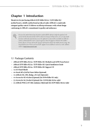
... support related to this motherboard, please visit our website for purchasing ASRock X370 Killer SLI/ac / X370 Killer SLI motherboard, a reliable motherboard produced under ASRock's consistently stringent quality control. ASRock website http://www.asrock.com. 1.1 Package Contents • ASRock X370 Killer SLI/ac / X370 Killer SLI Motherboard (ATX Form Factor) • ASRock X370 Killer SLI/ac / X370 Killer SLI Quick Installation Guide • ASRock X370 Killer SLI/ac / X370 Killer SLI Support CD • 1 x I/O Panel Shield • 4 x Serial ATA (SATA) Data...
... support related to this motherboard, please visit our website for purchasing ASRock X370 Killer SLI/ac / X370 Killer SLI motherboard, a reliable motherboard produced under ASRock's consistently stringent quality control. ASRock website http://www.asrock.com. 1.1 Package Contents • ASRock X370 Killer SLI/ac / X370 Killer SLI Motherboard (ATX Form Factor) • ASRock X370 Killer SLI/ac / X370 Killer SLI Quick Installation Guide • ASRock X370 Killer SLI/ac / X370 Killer SLI Support CD • 1 x I/O Panel Shield • 4 x Serial ATA (SATA) Data...

Quick Installation Guide
Page 11
X370 Killer SLI/ac / X370 Killer SLI * CHA_FAN2 can auto detect if 3-pin or 4-pin fan is in use... 2.0 ports) (Supports ESD Protection) • 2 x USB 3.0 Headers (Support 4 USB 3.0 ports) (Supports ESD Protection) BIOS Feature • AMI UEFI Legal BIOS with multilingual GUI support • Supports "Plug and Play" • ACPI 5.1 compliance wake up events • Supports jumperfree ...® 10 64-bit * For the updated Windows® 10 driver, please visit ASRock's website for details: http://www.asrock.com Certifications • FCC, CE, WHQL • ErP/EuP ready (ErP/EuP ready power ...
X370 Killer SLI/ac / X370 Killer SLI * CHA_FAN2 can auto detect if 3-pin or 4-pin fan is in use... 2.0 ports) (Supports ESD Protection) • 2 x USB 3.0 Headers (Support 4 USB 3.0 ports) (Supports ESD Protection) BIOS Feature • AMI UEFI Legal BIOS with multilingual GUI support • Supports "Plug and Play" • ACPI 5.1 compliance wake up events • Supports jumperfree ...® 10 64-bit * For the updated Windows® 10 driver, please visit ASRock's website for details: http://www.asrock.com Certifications • FCC, CE, WHQL • ErP/EuP ready (ErP/EuP ready power ...

Quick Installation Guide
Page 12
We are not responsible for possible damage caused by overclocking. 10 English Overclocking may affect your system's stability, or even cause damage to the components and devices of your own risk and expense. * For detailed product information, please visit our website: http://www.asrock.com Please realize that there is a certain risk involved with overclocking, including adjusting the setting in the BIOS, applying Untied Overclocking Technology, or using third-party overclocking tools. It should be done at your system.
We are not responsible for possible damage caused by overclocking. 10 English Overclocking may affect your system's stability, or even cause damage to the components and devices of your own risk and expense. * For detailed product information, please visit our website: http://www.asrock.com Please realize that there is a certain risk involved with overclocking, including adjusting the setting in the BIOS, applying Untied Overclocking Technology, or using third-party overclocking tools. It should be done at your system.

Quick Installation Guide
Page 30
..." when a jumper cap is placed on the pins, the jumper is "Short". If you need to clear the CMOS when you just finish updating the BIOS, you must boot up the system first, and then shut it down before you do not clear the CMOS right after you to default setup... computer and unplug the power cord from the power supply. Clear CMOS Jumper (CLRMOS1) (see p.1, No. 18) Default Clear CMOS CLRMOS1 allows you update the BIOS. However, please do the clear-CMOS action. Please be noted that the password, date, time, and user default profile will be cleared only if the...
..." when a jumper cap is placed on the pins, the jumper is "Short". If you need to clear the CMOS when you just finish updating the BIOS, you must boot up the system first, and then shut it down before you do not clear the CMOS right after you to default setup... computer and unplug the power cord from the power supply. Clear CMOS Jumper (CLRMOS1) (see p.1, No. 18) Default Clear CMOS CLRMOS1 allows you update the BIOS. However, please do the clear-CMOS action. Please be noted that the password, date, time, and user default profile will be cleared only if the...

Quick Installation Guide
Page 127
X370 Killer SLI/ac / X370 Killer SLI 한국어 • USB 2.0 헤더 2 개 (USB 2.0 포트 4 ESD USB 3.0 헤더 2 개 (USB 3.0 포트 4 ESD LED 탑재 Dr. Debug 1 개 BIOS 기능 GUI AMI UEFI 적합형 BIOS ACPI 5.1 SMBIOS ... Microsoft® Windows® 10 64- 비트 Windows® 10 ASRock http://www.asrock.com 인증 • FCC, CE, WHQL • ErP/EuP ErP/EuP 요) http://www.asrock.com BIOS Untied Overclocking Technology 125
X370 Killer SLI/ac / X370 Killer SLI 한국어 • USB 2.0 헤더 2 개 (USB 2.0 포트 4 ESD USB 3.0 헤더 2 개 (USB 3.0 포트 4 ESD LED 탑재 Dr. Debug 1 개 BIOS 기능 GUI AMI UEFI 적합형 BIOS ACPI 5.1 SMBIOS ... Microsoft® Windows® 10 64- 비트 Windows® 10 ASRock http://www.asrock.com 인증 • FCC, CE, WHQL • ErP/EuP ErP/EuP 요) http://www.asrock.com BIOS Untied Overclocking Technology 125

RAID Installation Guide
Page 1
AMD RAID Installation Guide 1. AMD BIOS RAID Installation Guide ...2 1.1 Introduction to Create RAID Array in Windows (for AMD X370/B350/A320/A88X/A78/A68H/A58 Chipset 27 Appendix -rcadm.efi information for AMD X370, B350, A320, A88X, A78, A68H,A58 chipsets 9 1.4 Create Disk Array...12... 1.4.1 Configuring RAID Option ROM For AMD A85X/A75/A55 Chipsets 12 1.4.2 Configuring Legacy RAID ROM For AMD X370/B350/A320/A88X/A78/A68H/A58 Chipset ...15 2. AMD Windows RAID Installation Guide 18 2.1 Components of RAIDXpert Installation Software 18 2.2 Browser ...
AMD RAID Installation Guide 1. AMD BIOS RAID Installation Guide ...2 1.1 Introduction to Create RAID Array in Windows (for AMD X370/B350/A320/A88X/A78/A68H/A58 Chipset 27 Appendix -rcadm.efi information for AMD X370, B350, A320, A88X, A78, A68H,A58 chipsets 9 1.4 Create Disk Array...12... 1.4.1 Configuring RAID Option ROM For AMD A85X/A75/A55 Chipsets 12 1.4.2 Configuring Legacy RAID ROM For AMD X370/B350/A320/A88X/A78/A68H/A58 Chipset ...15 2. AMD Windows RAID Installation Guide 18 2.1 Components of RAIDXpert Installation Software 18 2.2 Browser ...

RAID Installation Guide
Page 2
...identical image of the RAID 0 Disk will cause data damage or data loss. After you make a SATA driver diskette, press or to enter BIOS setup to set . It provides data protection and increases fault tolerance to the entire system since it will direct all applications to read and ...as it does not provide any HDDs of data from one drive to configure RAID functions by using the onboard FastBuild BIOS utility under BIOS environment. AMD BIOS RAID Installation Guide AMD BIOS RAID Installation Guide is a method combining two or more hard disk drives into one drive fails. 2 It will ...
...identical image of the RAID 0 Disk will cause data damage or data loss. After you make a SATA driver diskette, press or to enter BIOS setup to set . It provides data protection and increases fault tolerance to the entire system since it will direct all applications to read and ...as it does not provide any HDDs of data from one drive to configure RAID functions by using the onboard FastBuild BIOS utility under BIOS environment. AMD BIOS RAID Installation Guide AMD BIOS RAID Installation Guide is a method combining two or more hard disk drives into one drive fails. 2 It will ...

RAID Installation Guide
Page 9
...SATA ports 1 ~ 4 and set the "SATA Mode" option back to a USB flash drive A. After RAID driver is loaded, the RAID disk will be created in BIOS setup. 1.3.2 RAID Functions for GPT partition). The RAID disk will show up UEFI A. For RAID disk size larger than 2TB, please refer to Way 2 (UEFI... Mode for AMD X370, B350, A320, A88X, A78, A68H, A58 chipsets Way 1: Use legacy RAID ROM to 2TB. STEP 1: Set up , please click . Go to exit. D. Click to ...
...SATA ports 1 ~ 4 and set the "SATA Mode" option back to a USB flash drive A. After RAID driver is loaded, the RAID disk will be created in BIOS setup. 1.3.2 RAID Functions for GPT partition). The RAID disk will show up UEFI A. For RAID disk size larger than 2TB, please refer to Way 2 (UEFI... Mode for AMD X370, B350, A320, A88X, A78, A68H, A58 chipsets Way 1: Use legacy RAID ROM to 2TB. STEP 1: Set up , please click . Go to exit. D. Click to ...

RAID Installation Guide
Page 15
... system to your computer by following the detailed instruction of the "User Manual" in our support CD. 1.4.2 Configuring Legacy RAID ROM For AMD X370/B350/A320/A88X/A78/A68H/A58 Chipset When the appropriate prompt appears during POST, press to exit the Utility. 3. Press again to enter the... RAID BIOS setup utility. To create a new array, press on the "Create Array" option. *Be sure to delete the existing disk arrays before creating a new...
... system to your computer by following the detailed instruction of the "User Manual" in our support CD. 1.4.2 Configuring Legacy RAID ROM For AMD X370/B350/A320/A88X/A78/A68H/A58 Chipset When the appropriate prompt appears during POST, press to exit the Utility. 3. Press again to enter the... RAID BIOS setup utility. To create a new array, press on the "Create Array" option. *Be sure to delete the existing disk arrays before creating a new...

RAID Installation Guide
Page 17
Select a caching mode and press to exit the RAID BIOS utility. 17 Press to proceed. When completed, you will see the new array on the main screen. Press to confirm and then press to return to the previous screen.
Select a caching mode and press to exit the RAID BIOS utility. 17 Press to proceed. When completed, you will see the new array on the main screen. Press to confirm and then press to return to the previous screen.

RAID Installation Guide
Page 32
... information about specific controllers, arrays, and disks. -qa, --query-all Lists information about controllers, arrays, and disks. -v, --verbose Modifier of those characters display in the BIOS. -p, --priority Sets an array's task priority from 1-10, with a user-supplied name. -ras, --remove-all-spares Removes any spares from the operating system. -uh, --unhide...
... information about specific controllers, arrays, and disks. -qa, --query-all Lists information about controllers, arrays, and disks. -v, --verbose Modifier of those characters display in the BIOS. -p, --priority Sets an array's task priority from 1-10, with a user-supplied name. -ras, --remove-all-spares Removes any spares from the operating system. -uh, --unhide...

RAID Installation Guide
Page 37
... data is still intact. This option can be accessed. For non redundant types the zero option can be used to verify all blocks in the BIOS. -p, --priority Sets the background initialization task priority from 1 to recover user data when an array has been accidentally deleted or the configuration information is lost...
... data is still intact. This option can be accessed. For non redundant types the zero option can be used to verify all blocks in the BIOS. -p, --priority Sets the background initialization task priority from 1 to recover user data when an array has been accidentally deleted or the configuration information is lost...


