
Quick Installation Guide
Page 4
X570 Phantom Gaming X Motherboard Layout 1 23 4 5 67 BIOS _FB1 M2_WIFI_1 ATX12V1 CHA_FAN3/WP ATX12V2 RoHS CPU_FAN1 CPU_FAN2/WP PS2 Keyboard /Mouse USB 3.2 Gen1 T: USB1 B: USB2 ... 2.5GLAN (Realtek B: USB6 RTL8125AG) USB 3.2 Gen2 T: USB31_TA_1 B: USB31_TC_1 LAN X570 Phantom Gaming X Central/Bass LINE IN Top: Center: FRONT Bottom: MIC IN USB_5 1 AMD_FAN_LED1 M2_1 PCIE1 1 CHA_FAN4 /WP 33 SPI_TPM_J1 1 CMOS Battery PCIE2 AMD M2_2 BIOS ROM Premium X570 SATA3_1_2 USB3_7_8 1 CHA_FAN1/WP F_USB31_TC_1 SATA3_3_4 AUDIO CODEC PCIE3 SATA3_5_6 M2_3 PCIE4 SATA3_7_8...
X570 Phantom Gaming X Motherboard Layout 1 23 4 5 67 BIOS _FB1 M2_WIFI_1 ATX12V1 CHA_FAN3/WP ATX12V2 RoHS CPU_FAN1 CPU_FAN2/WP PS2 Keyboard /Mouse USB 3.2 Gen1 T: USB1 B: USB2 ... 2.5GLAN (Realtek B: USB6 RTL8125AG) USB 3.2 Gen2 T: USB31_TA_1 B: USB31_TC_1 LAN X570 Phantom Gaming X Central/Bass LINE IN Top: Center: FRONT Bottom: MIC IN USB_5 1 AMD_FAN_LED1 M2_1 PCIE1 1 CHA_FAN4 /WP 33 SPI_TPM_J1 1 CMOS Battery PCIE2 AMD M2_2 BIOS ROM Premium X570 SATA3_1_2 USB3_7_8 1 CHA_FAN1/WP F_USB31_TC_1 SATA3_3_4 AUDIO CODEC PCIE3 SATA3_5_6 M2_3 PCIE4 SATA3_7_8...

Quick Installation Guide
Page 24
X570 Phantom Gaming X 4 CPU_FAN1 5 RGB LED Cable 4-pin FAN cable CPU_FAN1 +12V AMD_FAN_LED1 *The diagrams shown here are for the orientation of AMD Fan LED Header (AMD_ FAN_LED1). 21 English Please refer to page 36 for reference only. The headers might be in a different position on your motherboard.
X570 Phantom Gaming X 4 CPU_FAN1 5 RGB LED Cable 4-pin FAN cable CPU_FAN1 +12V AMD_FAN_LED1 *The diagrams shown here are for the orientation of AMD Fan LED Header (AMD_ FAN_LED1). 21 English Please refer to page 36 for reference only. The headers might be in a different position on your motherboard.

Quick Installation Guide
Page 28
... AMD utility "SR3 Settings Software". *The diagrams shown here are for the orientation of AMD LED Fan USB Header (USB_5). 25 English X570 Phantom Gaming X 6 CPU_FAN1 +12V RGB_LED2 or 7 CPU_FAN1 AMD_FAN_LED1 USB_5 Please note that only one cable should be in this step. The headers might be used at a time in a different position on your motherboard...
... AMD utility "SR3 Settings Software". *The diagrams shown here are for the orientation of AMD LED Fan USB Header (USB_5). 25 English X570 Phantom Gaming X 6 CPU_FAN1 +12V RGB_LED2 or 7 CPU_FAN1 AMD_FAN_LED1 USB_5 Please note that only one cable should be in this step. The headers might be used at a time in a different position on your motherboard...

Quick Installation Guide
Page 29
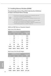
otherwise, this motherboard and DIMM may be damaged. 4. DR - We suggest that you always need to activate Dual Channel Memory Technology with only one or three memory module installed. 3. AMD non-XMP Memory Frequency Support Ryzen Series CPUs (Matisse): UDIMM Memory Slot A1 A2 B1 B2 Frequency (Mhz) - DR - - 3200 - DR - - 2933 -... SR/DR DR SR/DR DR 2667 SR/DR SR/DR SR/DR SR/DR 2133-2400 26 English 2.3 Installing Memory Modules (DIMM) This motherboard provides four 288-pin DDR4 (Double Data Rate 4) DIMM slots, and supports Dual Channel Memory Technology. 1.
otherwise, this motherboard and DIMM may be damaged. 4. DR - We suggest that you always need to activate Dual Channel Memory Technology with only one or three memory module installed. 3. AMD non-XMP Memory Frequency Support Ryzen Series CPUs (Matisse): UDIMM Memory Slot A1 A2 B1 B2 Frequency (Mhz) - DR - - 3200 - DR - - 2933 -... SR/DR DR SR/DR DR 2667 SR/DR SR/DR SR/DR SR/DR 2133-2400 26 English 2.3 Installing Memory Modules (DIMM) This motherboard provides four 288-pin DDR4 (Double Data Rate 4) DIMM slots, and supports Dual Channel Memory Technology. 1.

Quick Installation Guide
Page 35
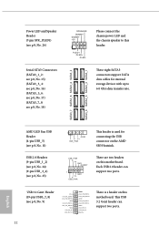
... IntA_PA_DIntA_PA_D+ Vbus IntA_PB_SSRXIntA_PB_SSRX+ GND IntA_PB_SSTXIntA_PB_SSTX+ GND IntA_PB_DIntA_PB_D+ Dummy 1 There is used for internal storage devices with up to this motherboard. Each USB 2.0 header can support two ports. 32 English Power LED and Speaker Header (7-pin SPK_PLED1) (see p.1, No.... 25) 1 GND P- These eight SATA3 connectors support SATA data cables for connecting the USB connector on this motherboard. SATA3_7 SATA3_6 SATA3_4 SATA3_2 SATA3_8 SATA3_5 SATA3_3 SATA3_1 AMD LED Fan USB Header (4-pin USB_5) (see p.1, No. 11) USB 2.0 Headers (9-pin USB_1_2) (see...
... IntA_PA_DIntA_PA_D+ Vbus IntA_PB_SSRXIntA_PB_SSRX+ GND IntA_PB_SSTXIntA_PB_SSTX+ GND IntA_PB_DIntA_PB_D+ Dummy 1 There is used for internal storage devices with up to this motherboard. Each USB 2.0 header can support two ports. 32 English Power LED and Speaker Header (7-pin SPK_PLED1) (see p.1, No.... 25) 1 GND P- These eight SATA3 connectors support SATA data cables for connecting the USB connector on this motherboard. SATA3_7 SATA3_6 SATA3_4 SATA3_2 SATA3_8 SATA3_5 SATA3_3 SATA3_1 AMD LED Fan USB Header (4-pin USB_5) (see p.1, No. 11) USB 2.0 Headers (9-pin USB_1_2) (see...
User Manual
Page 15
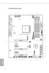
1.3 Motherboard Layout 1 23 4 5 67 BIOS _FB1 M2_WIFI_1 ATX12V1 CHA_FAN3/WP ATX12V2 RoHS CPU_FAN1 CPU_FAN2/WP PS2 Keyboard /Mouse USB 3.2 Gen1 T: USB1 B: USB2 ATXPWR1 ... T: USB5 2.5GLAN (Realtek B: USB6 RTL8125AG) USB 3.2 Gen2 T: USB31_TA_1 B: USB31_TC_1 LAN X570 Phantom Gaming X Central/Bass LINE IN Top: Center: FRONT Bottom: MIC IN USB_5 1 AMD_FAN_LED1 M2_1 PCIE1 1 CHA_FAN4 /WP 33 SPI_TPM_J1 1 CMOS Battery PCIE2 AMD M2_2 BIOS ROM Premium X570 SATA3_1_2 USB3_7_8 1 CHA_FAN1/WP F_USB31_TC_1 SATA3_3_4 AUDIO CODEC PCIE3 SATA3_5_6 M2_3 PCIE4 SATA3_7_8...
1.3 Motherboard Layout 1 23 4 5 67 BIOS _FB1 M2_WIFI_1 ATX12V1 CHA_FAN3/WP ATX12V2 RoHS CPU_FAN1 CPU_FAN2/WP PS2 Keyboard /Mouse USB 3.2 Gen1 T: USB1 B: USB2 ATXPWR1 ... T: USB5 2.5GLAN (Realtek B: USB6 RTL8125AG) USB 3.2 Gen2 T: USB31_TA_1 B: USB31_TC_1 LAN X570 Phantom Gaming X Central/Bass LINE IN Top: Center: FRONT Bottom: MIC IN USB_5 1 AMD_FAN_LED1 M2_1 PCIE1 1 CHA_FAN4 /WP 33 SPI_TPM_J1 1 CMOS Battery PCIE2 AMD M2_2 BIOS ROM Premium X570 SATA3_1_2 USB3_7_8 1 CHA_FAN1/WP F_USB31_TC_1 SATA3_3_4 AUDIO CODEC PCIE3 SATA3_5_6 M2_3 PCIE4 SATA3_7_8...
User Manual
Page 28
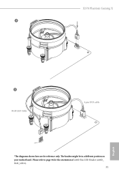
Please refer to page 36 for reference only. X570 Phantom Gaming X 4 CPU_FAN1 5 RGB LED Cable 4-pin FAN cable CPU_FAN1 +12V AMD_FAN_LED1 *The diagrams shown here are for the orientation of AMD Fan LED Header (AMD_ FAN_LED1). 21 English The headers might be in a different position on your motherboard.
Please refer to page 36 for reference only. X570 Phantom Gaming X 4 CPU_FAN1 5 RGB LED Cable 4-pin FAN cable CPU_FAN1 +12V AMD_FAN_LED1 *The diagrams shown here are for the orientation of AMD Fan LED Header (AMD_ FAN_LED1). 21 English The headers might be in a different position on your motherboard.
User Manual
Page 32
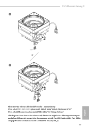
X570 Phantom Gaming X 6 CPU_FAN1 +12V RGB_LED2 or 7 CPU_FAN1 AMD_FAN_LED1 USB_5 Please note that only one cable should be in this step. If you select AMD_FAN_LED1, please install ASRock utility "ASRock Polychrome SYNC". The headers might be used at a time in a different position on your motherboard. If you select USB connector, please install AMD utility "SR3 Settings Software". *The...
X570 Phantom Gaming X 6 CPU_FAN1 +12V RGB_LED2 or 7 CPU_FAN1 AMD_FAN_LED1 USB_5 Please note that only one cable should be in this step. If you select AMD_FAN_LED1, please install ASRock utility "ASRock Polychrome SYNC". The headers might be used at a time in a different position on your motherboard. If you select USB connector, please install AMD utility "SR3 Settings Software". *The...
User Manual
Page 33
... and DDR4_B2 first for better DRAM compatibility on 2 DIMMs configuration. AMD non-XMP Memory Frequency Support Ryzen Series CPUs (Matisse): UDIMM Memory Slot A1 A2 B1 B2 Frequency (Mhz) - DR - - 3200 - DR - otherwise, this motherboard and DIMM may be damaged. 4. SR - - 3200 - ...): UDIMM Memory Slot A1 A2 B1 B2 Frequency (Mhz) - SR - - 2933 - SR - 2.3 Installing Memory Modules (DIMM) This motherboard provides four 288-pin DDR4 (Double Data Rate 4) DIMM slots, and supports Dual Channel Memory Technology. 1. It is not allowed to install ...
... and DDR4_B2 first for better DRAM compatibility on 2 DIMMs configuration. AMD non-XMP Memory Frequency Support Ryzen Series CPUs (Matisse): UDIMM Memory Slot A1 A2 B1 B2 Frequency (Mhz) - DR - - 3200 - DR - otherwise, this motherboard and DIMM may be damaged. 4. SR - - 3200 - ...): UDIMM Memory Slot A1 A2 B1 B2 Frequency (Mhz) - SR - - 2933 - SR - 2.3 Installing Memory Modules (DIMM) This motherboard provides four 288-pin DDR4 (Double Data Rate 4) DIMM slots, and supports Dual Channel Memory Technology. 1. It is not allowed to install ...
User Manual
Page 39
P+ USB_PWR This header is a header on the AMD SR3 Heatsink. USB_PWR PP+ GND DUMMY 1 GND P+ PUSB_PWR There are two headers on this motherboard. Each USB 2.0 header can support two ports. 32 English These eight SATA3 connectors support SATA data cables for connecting the USB connector on this motherboard. Power LED and Speaker Header (7-pin...
P+ USB_PWR This header is a header on the AMD SR3 Heatsink. USB_PWR PP+ GND DUMMY 1 GND P+ PUSB_PWR There are two headers on this motherboard. Each USB 2.0 header can support two ports. 32 English These eight SATA3 connectors support SATA data cables for connecting the USB connector on this motherboard. Power LED and Speaker Header (7-pin...

User Manual
Page 55
... to install up to PCIE3 slot. If you pair a 12-pipe CrossFireXTM Edition card with this motherboard. Make sure that your graphics card driver supports AMD CrossFireXTM technology. Make sure that your power supply unit (PSU) can provide at least the minimum .... 2. You should only use a AMD certified PSU. CrossFire Bridge Step 2 Connect two graphics cards by installing a CrossFire Bridge on the CrossFire Bridge Interconnects on the slots. 2.10 CrossFireXTM , 3-Way CrossFireXTM and Quad CrossFireXTM Operation Guide This motherboard supports CrossFireXTM, 3-way CrossFireXTM and Quad ...
... to install up to PCIE3 slot. If you pair a 12-pipe CrossFireXTM Edition card with this motherboard. Make sure that your graphics card driver supports AMD CrossFireXTM technology. Make sure that your power supply unit (PSU) can provide at least the minimum .... 2. You should only use a AMD certified PSU. CrossFire Bridge Step 2 Connect two graphics cards by installing a CrossFire Bridge on the CrossFire Bridge Interconnects on the slots. 2.10 CrossFireXTM , 3-Way CrossFireXTM and Quad CrossFireXTM Operation Guide This motherboard supports CrossFireXTM, 3-way CrossFireXTM and Quad ...


