
Quick Installation Guide
Page 1
... loss of profits, loss of business, loss of data, interruption of business and the like), even if ASRock has been advised of the possibility of such damages arising from any means, except duplication of this motherboard contains Perchlorate, a toxic substance controlled in advance. Copyright Notice: No part of documentation by the California...
... loss of profits, loss of business, loss of data, interruption of business and the like), even if ASRock has been advised of the possibility of such damages arising from any means, except duplication of this motherboard contains Perchlorate, a toxic substance controlled in advance. Copyright Notice: No part of documentation by the California...

Quick Installation Guide
Page 4
X570 Phantom Gaming X Motherboard Layout 1 23 4 5 67 BIOS _FB1 M2_WIFI_1 ATX12V1 CHA_FAN3/WP ATX12V2 RoHS CPU_FAN1 CPU_FAN2/WP PS2 Keyboard /Mouse USB 3.2 Gen1 T: USB1 B: USB2 ATXPWR1 DDR4_A1 (64 bit,... USB4 (I211AT) LAN SOCKET AM4 Bottom: Optical SPDIF Center: REAR SPK Top: USB 3.2 Gen1 Top: T: USB5 2.5GLAN (Realtek B: USB6 RTL8125AG) USB 3.2 Gen2 T: USB31_TA_1 B: USB31_TC_1 LAN X570 Phantom Gaming X Central/Bass LINE IN Top: Center: FRONT Bottom: MIC IN USB_5 1 AMD_FAN_LED1 M2_1 PCIE1 1 CHA_FAN4 /WP 33 SPI_TPM_J1 1 CMOS Battery PCIE2 AMD M2_2 BIOS ROM...
X570 Phantom Gaming X Motherboard Layout 1 23 4 5 67 BIOS _FB1 M2_WIFI_1 ATX12V1 CHA_FAN3/WP ATX12V2 RoHS CPU_FAN1 CPU_FAN2/WP PS2 Keyboard /Mouse USB 3.2 Gen1 T: USB1 B: USB2 ATXPWR1 DDR4_A1 (64 bit,... USB4 (I211AT) LAN SOCKET AM4 Bottom: Optical SPDIF Center: REAR SPK Top: USB 3.2 Gen1 Top: T: USB5 2.5GLAN (Realtek B: USB6 RTL8125AG) USB 3.2 Gen2 T: USB31_TA_1 B: USB31_TC_1 LAN X570 Phantom Gaming X Central/Bass LINE IN Top: Center: FRONT Bottom: MIC IN USB_5 1 AMD_FAN_LED1 M2_1 PCIE1 1 CHA_FAN4 /WP 33 SPI_TPM_J1 1 CMOS Battery PCIE2 AMD M2_2 BIOS ROM...
Quick Installation Guide
Page 9
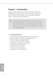
... specific information about the model you require technical support related to this motherboard, please visit our website for purchasing ASRock X570 Phantom Gaming X motherboard, a reliable motherboard produced under ASRock's consistently stringent quality control. ASRock website http://www.asrock.com. 1.1 Package Contents • ASRock X570 Phantom Gaming X Motherboard (ATX Form Factor) • ASRock X570 Phantom Gaming X Quick Installation Guide • ASRock X570 Phantom Gaming X Support CD • 4 x Serial ATA (SATA) Data Cables (Optional) •...
... specific information about the model you require technical support related to this motherboard, please visit our website for purchasing ASRock X570 Phantom Gaming X motherboard, a reliable motherboard produced under ASRock's consistently stringent quality control. ASRock website http://www.asrock.com. 1.1 Package Contents • ASRock X570 Phantom Gaming X Motherboard (ATX Form Factor) • ASRock X570 Phantom Gaming X Quick Installation Guide • ASRock X570 Phantom Gaming X Support CD • 4 x Serial ATA (SATA) Data Cables (Optional) •...
Quick Installation Guide
Page 16
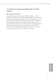
.... WiFi + BT module is an easy-touse wireless local area network (WLAN) adapter to the environment. 13 English X570 Phantom Gaming X 1.3 WiFi-802.11ax Module and ASRock WiFi 2.4/5 GHz Antenna WiFi-802.11ax + BT Module This motherboard comes with an exclusive WiFi 802.11 a/b/g/n/ax + BT v5.0 module (pre-installed on the rear I/O panel) that...
.... WiFi + BT module is an easy-touse wireless local area network (WLAN) adapter to the environment. 13 English X570 Phantom Gaming X 1.3 WiFi-802.11ax Module and ASRock WiFi 2.4/5 GHz Antenna WiFi-802.11ax + BT Module This motherboard comes with an exclusive WiFi 802.11 a/b/g/n/ax + BT v5.0 module (pre-installed on the rear I/O panel) that...

Quick Installation Guide
Page 17
...components. • Hold components by the edges and do not touch the ICs. • Whenever you uninstall any motherboard settings. • Make sure to you install motherboard components or change any components, place them on a carpet. Doing so may cause physical injuries to unplug the ...power cord before you and damages to motherboard components. • In order to avoid damage from static electricity to the motherboard's components, NEVER place your chassis to ensure that comes with the components. • When placing...
...components. • Hold components by the edges and do not touch the ICs. • Whenever you uninstall any motherboard settings. • Make sure to you install motherboard components or change any components, place them on a carpet. Doing so may cause physical injuries to unplug the ...power cord before you and damages to motherboard components. • In order to avoid damage from static electricity to the motherboard's components, NEVER place your chassis to ensure that comes with the components. • When placing...

Quick Installation Guide
Page 20
Please turn off the power or remove the power cord before changing a CPU or heatsink. Installing the CPU Box Cooler SR1 1 2 17 English Make sure that the CPU and the heatsink are securely fastened and in good contact with each other. X570 Phantom Gaming X 2.2 Installing the CPU Fan and Heatsink After you install the CPU into this motherboard, it is necessary to install a larger heatsink and cooling fan to improve heat dissipation. You also need to spray thermal grease between the CPU and the heatsink to dissipate heat.
Please turn off the power or remove the power cord before changing a CPU or heatsink. Installing the CPU Box Cooler SR1 1 2 17 English Make sure that the CPU and the heatsink are securely fastened and in good contact with each other. X570 Phantom Gaming X 2.2 Installing the CPU Fan and Heatsink After you install the CPU into this motherboard, it is necessary to install a larger heatsink and cooling fan to improve heat dissipation. You also need to spray thermal grease between the CPU and the heatsink to dissipate heat.

Quick Installation Guide
Page 24
The headers might be in a different position on your motherboard. Please refer to page 36 for reference only. X570 Phantom Gaming X 4 CPU_FAN1 5 RGB LED Cable 4-pin FAN cable CPU_FAN1 +12V AMD_FAN_LED1 *The diagrams shown here are for the orientation of AMD Fan LED Header (AMD_ FAN_LED1). 21 English
The headers might be in a different position on your motherboard. Please refer to page 36 for reference only. X570 Phantom Gaming X 4 CPU_FAN1 5 RGB LED Cable 4-pin FAN cable CPU_FAN1 +12V AMD_FAN_LED1 *The diagrams shown here are for the orientation of AMD Fan LED Header (AMD_ FAN_LED1). 21 English

Quick Installation Guide
Page 28
... headers might be used at a time in a different position on your motherboard. Please refer to page 36 for the orientation of AMD Fan LED Header (AMD_FAN_LED1) and page 32 for reference only. If you select AMD_FAN_LED1, please install ASRock utility "ASRock Polychrome SYNC". X570 Phantom Gaming X 6 CPU_FAN1 +12V RGB_LED2 or 7 CPU_FAN1 AMD_FAN_LED1 USB_5 Please note that...
... headers might be used at a time in a different position on your motherboard. Please refer to page 36 for the orientation of AMD Fan LED Header (AMD_FAN_LED1) and page 32 for reference only. If you select AMD_FAN_LED1, please install ASRock utility "ASRock Polychrome SYNC". X570 Phantom Gaming X 6 CPU_FAN1 +12V RGB_LED2 or 7 CPU_FAN1 AMD_FAN_LED1 USB_5 Please note that...

Quick Installation Guide
Page 29
...better DRAM compatibility on 2 DIMMs configuration. It is not allowed to install a DDR, DDR2 or DDR3 memory module into a DDR4 slot; otherwise, this motherboard and DIMM may be damaged. 4. SR - SR 3200 - DR - - 2933 - DR 3200 SR SR SR SR 2933 SR/DR DR SR...SR/DR 2667 Ryzen Series CPUs (Pinnacle Ridge): UDIMM Memory Slot A1 A2 B1 B2 Frequency (Mhz) - 2.3 Installing Memory Modules (DIMM) This motherboard provides four 288-pin DDR4 (Double Data Rate 4) DIMM slots, and supports Dual Channel Memory Technology. 1. It is unable to install identical (...
...better DRAM compatibility on 2 DIMMs configuration. It is not allowed to install a DDR, DDR2 or DDR3 memory module into a DDR4 slot; otherwise, this motherboard and DIMM may be damaged. 4. SR - SR 3200 - DR - - 2933 - DR 3200 SR SR SR SR 2933 SR/DR DR SR...SR/DR 2667 Ryzen Series CPUs (Pinnacle Ridge): UDIMM Memory Slot A1 A2 B1 B2 Frequency (Mhz) - 2.3 Installing Memory Modules (DIMM) This motherboard provides four 288-pin DDR4 (Double Data Rate 4) DIMM slots, and supports Dual Channel Memory Technology. 1. It is unable to install identical (...

Quick Installation Guide
Page 31
It will cause permanent damage to the motherboard and the DIMM if you force the DIMM into the slot at incorrect orientation. 1 2 3 28 English The DIMM only fits in one correct orientation.
It will cause permanent damage to the motherboard and the DIMM if you force the DIMM into the slot at incorrect orientation. 1 2 3 28 English The DIMM only fits in one correct orientation.

Quick Installation Guide
Page 32
...better thermal environment, please connect a chassis fan to the motherboard's chassis fan connector (CHA_FAN1/WP, CHA_FAN2/WP , CHA_FAN3/WP or CHA_FAN4/WP ) when using multiple graphics cards. PCIE3 (PCIe 4.0 x16 slot) is unplugged. X570 Phantom Gaming X 2.4 Expansion Slots (PCI Express Slots) There are 5... PCI Express slots on the motherboard. Before installing an expansion card, please make necessary hardware settings for PCI Express ...
...better thermal environment, please connect a chassis fan to the motherboard's chassis fan connector (CHA_FAN1/WP, CHA_FAN2/WP , CHA_FAN3/WP or CHA_FAN4/WP ) when using multiple graphics cards. PCIE3 (PCIe 4.0 x16 slot) is unplugged. X570 Phantom Gaming X 2.4 Expansion Slots (PCI Express Slots) There are 5... PCI Express slots on the motherboard. Before installing an expansion card, please make necessary hardware settings for PCI Express ...

Quick Installation Guide
Page 34
... or powered off (S5). The LED is operating. HDLED (Hard Drive Activity LED): Connect to the motherboard. A front panel module mainly consists of power button, reset button, power LED, hard drive activity LED, speaker and etc. X570 Phantom Gaming X 2.6 Onboard Headers and Connectors Onboard headers and connectors are matched correctly. Press the reset button...
... or powered off (S5). The LED is operating. HDLED (Hard Drive Activity LED): Connect to the motherboard. A front panel module mainly consists of power button, reset button, power LED, hard drive activity LED, speaker and etc. X570 Phantom Gaming X 2.6 Onboard Headers and Connectors Onboard headers and connectors are matched correctly. Press the reset button...

Quick Installation Guide
Page 35
...No. 9) Vbus IntA_PA_SSRXIntA_PA_SSRX+ GND IntA_PA_SSTXIntA_PA_SSTX+ GND IntA_PA_DIntA_PA_D+ Vbus IntA_PB_SSRXIntA_PB_SSRX+ GND IntA_PB_SSTXIntA_PB_SSTX+ GND IntA_PB_DIntA_PB_D+ Dummy 1 There is used for internal storage devices with up to this motherboard. Each USB 2.0 header can support two ports. 32 English Please connect the chassis power LED and the chassis speaker to 6.0 Gb/s data transfer rate. These... p.1, No. 18) SPEAKER DUMMY DUMMY +5V 1 PLED+ PLED+ PLED- This USB 3.2 Gen1 header can support two ports. P+ USB_PWR This header is a header on this motherboard.
...No. 9) Vbus IntA_PA_SSRXIntA_PA_SSRX+ GND IntA_PA_SSTXIntA_PA_SSTX+ GND IntA_PA_DIntA_PA_D+ Vbus IntA_PB_SSRXIntA_PB_SSRX+ GND IntA_PB_SSTXIntA_PB_SSTX+ GND IntA_PB_DIntA_PB_D+ Dummy 1 There is used for internal storage devices with up to this motherboard. Each USB 2.0 header can support two ports. 32 English Please connect the chassis power LED and the chassis speaker to 6.0 Gb/s data transfer rate. These... p.1, No. 18) SPEAKER DUMMY DUMMY +5V 1 PLED+ PLED+ PLED- This USB 3.2 Gen1 header can support two ports. P+ USB_PWR This header is a header on this motherboard.

Quick Installation Guide
Page 36
X570 Phantom Gaming X Front Panel Type C USB 3.2 Gen2 Header (26-pin F_USB31_TC_1) (see p.1, No. 13) USB Type-C Cable There is one Front Panel Type C USB 3.2 Gen2 Header on ... used for connecting a USB 3.2 Gen2 module for the HD audio panel only. Front Panel Audio Header (9-pin HD_AUDIO1) (see p.1, No. 3) FAN_SPEED_CONTROL CHA_FAN_SPEED FAN_VOLTAGE GND 4 This motherboard 3 2 provides four 4-Pin water 1 cooling chassis fan connectors. Connect Mic_IN (MIC) to function correctly. High Definition Audio supports Jack Sensing, but the panel wire on...
X570 Phantom Gaming X Front Panel Type C USB 3.2 Gen2 Header (26-pin F_USB31_TC_1) (see p.1, No. 13) USB Type-C Cable There is one Front Panel Type C USB 3.2 Gen2 Header on ... used for connecting a USB 3.2 Gen2 module for the HD audio panel only. Front Panel Audio Header (9-pin HD_AUDIO1) (see p.1, No. 3) FAN_SPEED_CONTROL CHA_FAN_SPEED FAN_VOLTAGE GND 4 This motherboard 3 2 provides four 4-Pin water 1 cooling chassis fan connectors. Connect Mic_IN (MIC) to function correctly. High Definition Audio supports Jack Sensing, but the panel wire on...

Quick Installation Guide
Page 37
...Warning: Please make sure that the power cable connected is for the CPU and not the graphics card. English This motherboard provides an 8-pin ATX 12V power connector. This motherboard provides a 4-Pin water cooling CPU fan connector. To use a 20-pin ATX power supply, please plug it... along Pin 1 and Pin 13. This motherboard provides a 24-pin ATX power connector. (4-pin CHA_FAN4/WP) 1 2 (see p.1, No. 14) 3 4 GND FAN_VOLTAGE CHA_FAN_SPEED FAN_SPEED_CONTROL CPU Fan Connector (4-pin ...
...Warning: Please make sure that the power cable connected is for the CPU and not the graphics card. English This motherboard provides an 8-pin ATX 12V power connector. This motherboard provides a 4-Pin water cooling CPU fan connector. To use a 20-pin ATX power supply, please plug it... along Pin 1 and Pin 13. This motherboard provides a 24-pin ATX power connector. (4-pin CHA_FAN4/WP) 1 2 (see p.1, No. 14) 3 4 GND FAN_VOLTAGE CHA_FAN_SPEED FAN_SPEED_CONTROL CPU Fan Connector (4-pin ...

Quick Installation Guide
Page 40
... (RSTBTN) (see p.1, No. 19) Clear CMOS Buttons allow users to quickly turn on /off your computer and unplug the power supply. English 37 X570 Phantom Gaming X 2.7 Smart Switches The motherboard has four smart switches: Power Button, Reset Button and Clear CMOS Buttons , allowing users to quickly clear the CMOS values. This function is workable...
... (RSTBTN) (see p.1, No. 19) Clear CMOS Buttons allow users to quickly turn on /off your computer and unplug the power supply. English 37 X570 Phantom Gaming X 2.7 Smart Switches The motherboard has four smart switches: Power Button, Reset Button and Clear CMOS Buttons , allowing users to quickly clear the CMOS values. This function is workable...

Quick Installation Guide
Page 41
...Please make sure that the BIOS Flashback is no need to the motherboard. Please make sure the file system of X: USB flash drive....and save it to blink. 8. Then the LED starts to the root directory of your USB flash drive. ASRock BIOS Flashback feature allows you plug the USB drive to update BIOS without powering on the power supply's AC... switch. *There is not operating properly. Extract BIOS file from ASRock's website : http://www.asrock.com. 2. Then plug your USB drive to flash the BIOS. BIOS Flashback Button (BIOS_FB1) (see ...
...Please make sure that the BIOS Flashback is no need to the motherboard. Please make sure the file system of X: USB flash drive....and save it to blink. 8. Then the LED starts to the root directory of your USB flash drive. ASRock BIOS Flashback feature allows you plug the USB drive to update BIOS without powering on the power supply's AC... switch. *There is not operating properly. Extract BIOS file from ASRock's website : http://www.asrock.com. 2. Then plug your USB drive to flash the BIOS. BIOS Flashback Button (BIOS_FB1) (see ...

Quick Installation Guide
Page 49
...) SSD module only fits in one orientation. Please be aware that comes with a screwdriver to remove the M.2 heatsink. *Please remove the protective films on the motherboard. Align and gently insert the M.2 (NGFF) SSD module into the desired nut location on the bottom side of the M.2 heatsink before you install a M.2 SSD module...
...) SSD module only fits in one orientation. Please be aware that comes with a screwdriver to remove the M.2 heatsink. *Please remove the protective films on the motherboard. Align and gently insert the M.2 (NGFF) SSD module into the desired nut location on the bottom side of the M.2 heatsink before you install a M.2 SSD module...

Quick Installation Guide
Page 51
Installing the M.2_SSD (NGFF) Module Step 1 This motherboard supports M.2_SSD (NGFF) module type 2260 and 2280 only. Step 2 Depending on the PCB type and length of module, the screw and the standoff. B A No. ...
Installing the M.2_SSD (NGFF) Module Step 1 This motherboard supports M.2_SSD (NGFF) module type 2260 and 2280 only. Step 2 Depending on the PCB type and length of module, the screw and the standoff. B A No. ...

Quick Installation Guide
Page 52
... that comes with a screwdriver to remove the M.2 heatsink. *Please remove the protective films on the motherboard. Please do not overtighten the screw as this might damage the module. 49 English Then hand tighten the standoff into place. 2 1 1 1 X570 Phantom Gaming X 1 Step 3 Before installing a M.2 (NGFF) SSD module, please loosen the screws to secure the module...
... that comes with a screwdriver to remove the M.2 heatsink. *Please remove the protective films on the motherboard. Please do not overtighten the screw as this might damage the module. 49 English Then hand tighten the standoff into place. 2 1 1 1 X570 Phantom Gaming X 1 Step 3 Before installing a M.2 (NGFF) SSD module, please loosen the screws to secure the module...


