
Intel Rapid Storage Guide
Page 12
... up or down arrow keys to create a RAID volume. 1. When finished press Enter. 12 Enable RAID in System BIOS Use the instructions included with your motherboard to enable RAID in the system BIOS, a RAID volume must be created, and the F6 installation method must be enabled in the system BIOS. 1. Switch...
... up or down arrow keys to create a RAID volume. 1. When finished press Enter. 12 Enable RAID in System BIOS Use the instructions included with your motherboard to enable RAID in the system BIOS, a RAID volume must be created, and the F6 installation method must be enabled in the system BIOS. 1. Switch...
RAID Installation Guide
Page 2
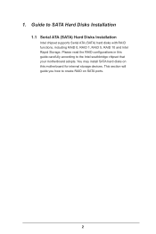
Guide to create RAID on this guide carefully according to the Intel southbridge chipset that your motherboard adopts. You may install SATA hard disks on SATA ports. 2 This section will guide you how to SATA Hard Disks Installation 1.1 Serial ATA (SATA) Hard Disks Installation Intel chipset supports Serial ATA (SATA) hard disks with RAID functions, including RAID 0, RAID 1, RAID 5, RAID 10 and Intel Rapid Storage. Please read the RAID configurations in this motherboard for internal storage devices. 1.
Guide to create RAID on this guide carefully according to the Intel southbridge chipset that your motherboard adopts. You may install SATA hard disks on SATA ports. 2 This section will guide you how to SATA Hard Disks Installation 1.1 Serial ATA (SATA) Hard Disks Installation Intel chipset supports Serial ATA (SATA) hard disks with RAID functions, including RAID 0, RAID 1, RAID 5, RAID 10 and Intel Rapid Storage. Please read the RAID configurations in this motherboard for internal storage devices. 1.
RAID Installation Guide
Page 3
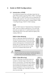
... array management software will introduce the basic knowledge of the data in parallel, interleaved stacks. 2. For optimal performance, please install identical drives of RAID This motherboard adopts Intel southbridge chipset that optimizes two identical hard disk drives to the surviving drive as a single drive but at a sustained data transfer rate. This...
... array management software will introduce the basic knowledge of the data in parallel, interleaved stacks. 2. For optimal performance, please install identical drives of RAID This motherboard adopts Intel southbridge chipset that optimizes two identical hard disk drives to the surviving drive as a single drive but at a sustained data transfer rate. This...
RAID Installation Guide
Page 23
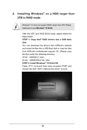
STEP 1: Copy Intel® RAID drivers into a USB flash disk You can download the drivers from ASRock's website and unzip the files into a USB flash disk or copy the files from ASRock's motherboard support CD. (Please copy the files under the following directory: 32 bit: ..\i386\Win7_Intel.. 64-bit: ..\AMD64\Win7-64_Intel.. STEP 2: Install...
STEP 1: Copy Intel® RAID drivers into a USB flash disk You can download the drivers from ASRock's website and unzip the files into a USB flash disk or copy the files from ASRock's motherboard support CD. (Please copy the files under the following directory: 32 bit: ..\i386\Win7_Intel.. 64-bit: ..\AMD64\Win7-64_Intel.. STEP 2: Install...
RAID Installation Guide
Page 25
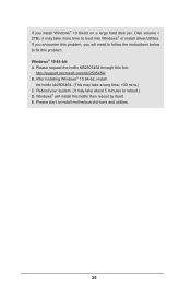
E. Reboot your system. (It may take about 5 minutes to install motherboard drivers and utilities. 25 Windows® will need to follow the instructions below to fix this problem. Windows® 10 64-bit: A. Please start to ...
E. Reboot your system. (It may take about 5 minutes to install motherboard drivers and utilities. 25 Windows® will need to follow the instructions below to fix this problem. Windows® 10 64-bit: A. Please start to ...
User Manual
Page 2
...related regulations in this documentation are used only for identification or explanation and to the implied warranties or conditions of this motherboard contains Perchlorate, a toxic substance controlled in any form or by any language, in Perchlorate Best Management Practices (BMP)... regulations passed by the California Legislature. Products and corporate names appearing in advance. ASRock assumes no event shall ASRock, its directors, officers, employees, or agents be reproduced, transcribed, transmitted, or translated in any means, except...
...related regulations in this documentation are used only for identification or explanation and to the implied warranties or conditions of this motherboard contains Perchlorate, a toxic substance controlled in any form or by any language, in Perchlorate Best Management Practices (BMP)... regulations passed by the California Legislature. Products and corporate names appearing in advance. ASRock assumes no event shall ASRock, its directors, officers, employees, or agents be reproduced, transcribed, transmitted, or translated in any means, except...
User Manual
Page 4
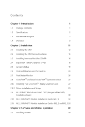
Contents Chapter 1 Introduction 1 1.1 Package Contents 1 1.2 Specifications 2 1.3 Motherboard Layout 7 1.4 I/O Panel 9 Chapter 2 Installation 11 2.1 Installing the CPU 12 2.2 Installing the CPU Fan and Heatsink 15 2.3 Installing Memory Modules (DIMM) 16 2.4 Expansion Slots (PCI Express ...
Contents Chapter 1 Introduction 1 1.1 Package Contents 1 1.2 Specifications 2 1.3 Motherboard Layout 7 1.4 I/O Panel 9 Chapter 2 Installation 11 2.1 Installing the CPU 12 2.2 Installing the CPU Fan and Heatsink 15 2.3 Installing Memory Modules (DIMM) 16 2.4 Expansion Slots (PCI Express ...
User Manual
Page 5
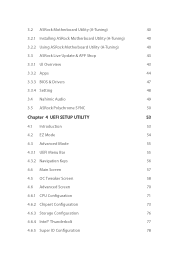
3.2 ASRock Motherboard Utility (A-Tuning) 40 3.2.1 Installing ASRock Motherboard Utility (A-Tuning) 40 3.2.2 Using ASRock Motherboard Utility (A-Tuning) 40 3.3 ASRock Live Update & APP Shop 43 3.3.1 UI Overview 43 3.3.2 Apps 44 3.3.3 BIOS & Drivers 47 3.3.4 Setting 48 3.4 Nahimic Audio 49 3.5 ASRock Polychrome SYNC 50 Chapter 4 UEFI SETUP UTILITY 53 4.1 Introduction 53 4.2 EZ Mode 54 4.3 Advanced Mode 55 4.3.1 UEFI Menu Bar 55 4.3.2 Navigation Keys...
3.2 ASRock Motherboard Utility (A-Tuning) 40 3.2.1 Installing ASRock Motherboard Utility (A-Tuning) 40 3.2.2 Using ASRock Motherboard Utility (A-Tuning) 40 3.3 ASRock Live Update & APP Shop 43 3.3.1 UI Overview 43 3.3.2 Apps 44 3.3.3 BIOS & Drivers 47 3.3.4 Setting 48 3.4 Nahimic Audio 49 3.5 ASRock Polychrome SYNC 50 Chapter 4 UEFI SETUP UTILITY 53 4.1 Introduction 53 4.2 EZ Mode 54 4.3 Advanced Mode 55 4.3.1 UEFI Menu Bar 55 4.3.2 Navigation Keys...

User Manual
Page 7
... cards and CPU support list on ASRock's website without notice. ASRock website http://www.asrock.com. 1.1 Package Contents • ASRock Z490 Steel Legend Motherboard (ATX Form Factor) • ASRock Z490 Steel Legend Quick Installation Guide • ASRock Z490 Steel Legend Support CD • 2 x Serial ATA (SATA) Data Cables (Optional) • 4 x Screws for M.2 Sockets (Optional) • 2 x Standoffs for purchasing ASRock Z490 Steel Legend motherboard, a reliable motherboard produced under ASRock's consistently stringent quality control. In...
... cards and CPU support list on ASRock's website without notice. ASRock website http://www.asrock.com. 1.1 Package Contents • ASRock Z490 Steel Legend Motherboard (ATX Form Factor) • ASRock Z490 Steel Legend Quick Installation Guide • ASRock Z490 Steel Legend Support CD • 2 x Serial ATA (SATA) Data Cables (Optional) • 4 x Screws for M.2 Sockets (Optional) • 2 x Standoffs for purchasing ASRock Z490 Steel Legend motherboard, a reliable motherboard produced under ASRock's consistently stringent quality control. In...
User Manual
Page 13
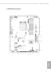
1.3 Motherboard Layout Z490 Steel Legend English 7
1.3 Motherboard Layout Z490 Steel Legend English 7
User Manual
Page 17
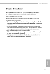
..., NEVER place your chassis to do not overtighten the screws! Z490 Steel Legend Chapter 2 Installation This is an ATX form factor motherboard. Also remember to the chassis, please do so may damage the motherboard. 11 English Before you uninstall any motherboard settings. • Make sure to unplug the power cord before you handle the components. •...
..., NEVER place your chassis to do not overtighten the screws! Z490 Steel Legend Chapter 2 Installation This is an ATX form factor motherboard. Also remember to the chassis, please do so may damage the motherboard. 11 English Before you uninstall any motherboard settings. • Make sure to unplug the power cord before you handle the components. •...
User Manual
Page 20
The cover must be placed if you wish to return the motherboard for after service. 14 English Please save and replace the cover if the processor is removed.
The cover must be placed if you wish to return the motherboard for after service. 14 English Please save and replace the cover if the processor is removed.
User Manual
Page 22
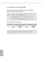
... a DDR, DDR2 or DDR3 memory module into the slot at incorrect orientation. otherwise, this motherboard and DIMM may be damaged. It will cause permanent damage to the motherboard and the DIMM if you always need to activate Dual Channel Memory Technology with only one correct... is unable to install identical (the same brand, speed, size and chip-type) DDR4 DIMM pairs. 2. 2.3 Installing Memory Modules (DIMM) This motherboard provides four 288-pin DDR4 (Double Data Rate 4) DIMM slots, and supports Dual Channel Memory Technology. 1. Dual Channel Memory Configuration Priority 1 2 ...
... a DDR, DDR2 or DDR3 memory module into the slot at incorrect orientation. otherwise, this motherboard and DIMM may be damaged. It will cause permanent damage to the motherboard and the DIMM if you always need to activate Dual Channel Memory Technology with only one correct... is unable to install identical (the same brand, speed, size and chip-type) DDR4 DIMM pairs. 2. 2.3 Installing Memory Modules (DIMM) This motherboard provides four 288-pin DDR4 (Double Data Rate 4) DIMM slots, and supports Dual Channel Memory Technology. 1. Dual Channel Memory Configuration Priority 1 2 ...
User Manual
Page 24
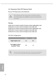
... Configurations Single Graphics Card PCIE1 x16 PCIE3 N/A Two Graphics Cards in CrossFireXTM Mode x16 x4 For a better thermal environment, please connect a chassis fan to the motherboard's chassis fan connector (CHA_FAN1~5/WP) when using multiple graphics cards. 2.4 Expansion Slots (PCI Express Slots) There are 5 PCI Express slots on the...
... Configurations Single Graphics Card PCIE1 x16 PCIE3 N/A Two Graphics Cards in CrossFireXTM Mode x16 x4 For a better thermal environment, please connect a chassis fan to the motherboard's chassis fan connector (CHA_FAN1~5/WP) when using multiple graphics cards. 2.4 Expansion Slots (PCI Express Slots) There are 5 PCI Express slots on the...
User Manual
Page 26
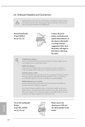
... design may configure the way to turn off when the system is operating. Please connect the chassis power LED and the chassis speaker to the motherboard. You may differ by chassis. 2.6 Onboard Headers and Connectors Onboard headers and connectors are matched correctly. Do NOT place jumper caps over the headers and...
... design may configure the way to turn off when the system is operating. Please connect the chassis power LED and the chassis speaker to the motherboard. You may differ by chassis. 2.6 Onboard Headers and Connectors Onboard headers and connectors are matched correctly. Do NOT place jumper caps over the headers and...
User Manual
Page 27
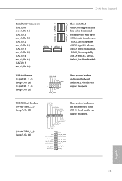
... ID Vbus IntA_PA_SSRXIntA_PA_SSRX+ GND IntA_PA_SSTXIntA_PA_SSTX+ GND IntA_PA_DIntA_PA_D+ Vbus IntA_PB_SSRXIntA_PB_SSRX+ GND IntA_PB_SSTXIntA_PB_SSTX+ GND IntA_PB_DIntA_PB_D+ Dummy 1 There are two headers on this motherboard. Z490 Steel Legend Serial ATA3 Connectors (SATA3_0: see p.7, No. 14) (SATA3_1: see p.7, No. 13) (SATA3_2: see p.7, No. 11) (... No. 19) (SATA3_5: see p.7, No. 25) USB_PWR PP+ GND DUMMY 1 GND P+ PUSB_PWR There are two headers on this motherboard. Each USB 3.2 Gen1 header can support two ports. USB 2.0 Headers (9-pin USB_3_4) (see p.7, No. 26) (9-pin USB_5_6) ...
... ID Vbus IntA_PA_SSRXIntA_PA_SSRX+ GND IntA_PA_SSTXIntA_PA_SSTX+ GND IntA_PA_DIntA_PA_D+ Vbus IntA_PB_SSRXIntA_PB_SSRX+ GND IntA_PB_SSTXIntA_PB_SSTX+ GND IntA_PB_DIntA_PB_D+ Dummy 1 There are two headers on this motherboard. Z490 Steel Legend Serial ATA3 Connectors (SATA3_0: see p.7, No. 14) (SATA3_1: see p.7, No. 13) (SATA3_2: see p.7, No. 11) (... No. 19) (SATA3_5: see p.7, No. 25) USB_PWR PP+ GND DUMMY 1 GND P+ PUSB_PWR There are two headers on this motherboard. Each USB 3.2 Gen1 header can support two ports. USB 2.0 Headers (9-pin USB_3_4) (see p.7, No. 26) (9-pin USB_5_6) ...
User Manual
Page 28
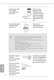
... a USB 3.2 Gen1 module for the AC'97 audio panel. Chassis/Water Pump Fan Connectors (4-pin CHA_FAN1/WP) FAN_SPEED_CONTROL CHA_FAN_SPEED FAN_VOLTAGE GND 4 This motherboard provides five 3 2 4-Pin water cooling chassis fan 1 connectors. If you use an AC'97 audio panel, please install it to Ground (GND...follow the instructions in the Realtek Control panel and adjust "Recording Volume". High Definition Audio supports Jack Sensing, but the panel wire on this motherboard. If you plan to con- (see p.7, No. 33) nect a 3-Pin chassis water cooler fan, please connect it to the front...
... a USB 3.2 Gen1 module for the AC'97 audio panel. Chassis/Water Pump Fan Connectors (4-pin CHA_FAN1/WP) FAN_SPEED_CONTROL CHA_FAN_SPEED FAN_VOLTAGE GND 4 This motherboard provides five 3 2 4-Pin water cooling chassis fan 1 connectors. If you use an AC'97 audio panel, please install it to Ground (GND...follow the instructions in the Realtek Control panel and adjust "Recording Volume". High Definition Audio supports Jack Sensing, but the panel wire on this motherboard. If you plan to con- (see p.7, No. 33) nect a 3-Pin chassis water cooler fan, please connect it to the front...

User Manual
Page 29
... a 3-Pin CPU fan, please connect it to this connector. Do not plug the PCIe power cable to Pin 1-3. 12 24 1 13 This motherboard provides a 24-pin ATX power connector. Z490 Steel Legend CPU Fan Connector (4-pin CPU_FAN1) (see p.7, No. 2) CPU/Water Pump Fan Connector (4-pin CPU_FAN2/ WP_3A) (see p.7, No. 5) ATX Power Connector (24-pin...
... a 3-Pin CPU fan, please connect it to this connector. Do not plug the PCIe power cable to Pin 1-3. 12 24 1 13 This motherboard provides a 24-pin ATX power connector. Z490 Steel Legend CPU Fan Connector (4-pin CPU_FAN1) (see p.7, No. 2) CPU/Water Pump Fan Connector (4-pin CPU_FAN2/ WP_3A) (see p.7, No. 5) ATX Power Connector (24-pin...
User Manual
Page 33
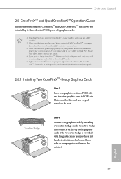
... PCIE1 slot and the other graphics card to enable CrossFireXTM. If you pair a 12-pipe CrossFireXTM Edition card with this motherboard. Different CrossFireXTM cards may require different methods to PCIE3 slot. CrossFire Bridge Step 2 Connect two graphics cards by installing a...that the cards are AMD certified. 2. Please refer to three identical PCI Express x16 graphics cards. 1. Z490 Steel Legend 2.8 CrossFireXTM and Quad CrossFireXTM Operation Guide This motherboard supports CrossFireXTM and Quad CrossFireXTM that allows you to install up to your graphics card vendor for details.)...
... PCIE1 slot and the other graphics card to enable CrossFireXTM. If you pair a 12-pipe CrossFireXTM Edition card with this motherboard. Different CrossFireXTM cards may require different methods to PCIE3 slot. CrossFire Bridge Step 2 Connect two graphics cards by installing a...that the cards are AMD certified. 2. Please refer to three identical PCI Express x16 graphics cards. 1. Z490 Steel Legend 2.8 CrossFireXTM and Quad CrossFireXTM Operation Guide This motherboard supports CrossFireXTM and Quad CrossFireXTM that allows you to install up to your graphics card vendor for details.)...
User Manual
Page 39
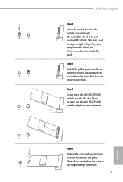
... Step 5 if you are going to secure the module into place. Step 5 Gently insert the M.2 (NGFF) SSD module into the desired nut location on the motherboard. B A Z490 Steel Legend Step 3 Move the standoff based on the nut to be aware that the M.2 (NGFF) SSD module only fits in one orientation. 20o English B A B NUT2 NUT1...
... Step 5 if you are going to secure the module into place. Step 5 Gently insert the M.2 (NGFF) SSD module into the desired nut location on the motherboard. B A Z490 Steel Legend Step 3 Move the standoff based on the nut to be aware that the M.2 (NGFF) SSD module only fits in one orientation. 20o English B A B NUT2 NUT1...


