User Manual
Page 5
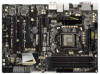
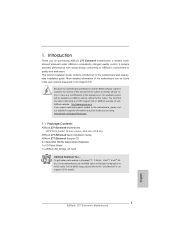
... , 30.5 cm x 21.8 cm) ASRock Z77 Extreme4 Quick Installation Guide ASRock Z77 Extreme4 Support CD 2 x Serial ATA (SATA) Data Cables (Optional) 1 x I/O Panel Shield 1 x ASRock SLI_Bridge_2S Card ASRock Reminds You... Because the motherboard specifications and the BIOS software might be updated, the content of the Support CD. www.asrock.com/support/index.asp 1.1 Package Contents ASRock Z77 Extreme4 Motherboard (ATX Form Factor: 12.0-in...
... , 30.5 cm x 21.8 cm) ASRock Z77 Extreme4 Quick Installation Guide ASRock Z77 Extreme4 Support CD 2 x Serial ATA (SATA) Data Cables (Optional) 1 x I/O Panel Shield 1 x ASRock SLI_Bridge_2S Card ASRock Reminds You... Because the motherboard specifications and the BIOS software might be updated, the content of the Support CD. www.asrock.com/support/index.asp 1.1 Package Contents ASRock Z77 Extreme4 Motherboard (ATX Form Factor: 12.0-in...
User Manual
Page 13
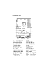
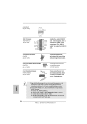
1.3 Motherboard Layout USB 3.0 T: USB0 B: USB1 PS2 Keyboard/ Mouse 1 21.8cm (8.6 in) ATX12V1 2 34 5 CPU_FAN1 PWR_FAN1 CPU_FAN2 6 ... Optical SPDIF Top: Center: Bottom: MIC IN CHA_FAN2 CHA_FAN3 38 37 PCIE1 Z77 Extreme4 8 9 USB3_4_5 AUDIO CODEC PCIE2 36 PCI Express 3.0 CMOS Battery ErP/EuP Ready Intel 10 35 PCI1 Z77 Super I/O X X X Fast USB Fast RAM Fast LAN 34 PCIE3 11... RSTBTN 12 13 14 31 30 29 28 27 26 25 24 23 22 21 20 19 18 17 16 15 1 ATX 12V Power Connector (ATX12V1) 21 Dr. Debug 2 1155-Pin CPU Socket 22 Chassis Fan Connector (CHA_FAN1) 3 CPU Fan...
1.3 Motherboard Layout USB 3.0 T: USB0 B: USB1 PS2 Keyboard/ Mouse 1 21.8cm (8.6 in) ATX12V1 2 34 5 CPU_FAN1 PWR_FAN1 CPU_FAN2 6 ... Optical SPDIF Top: Center: Bottom: MIC IN CHA_FAN2 CHA_FAN3 38 37 PCIE1 Z77 Extreme4 8 9 USB3_4_5 AUDIO CODEC PCIE2 36 PCI Express 3.0 CMOS Battery ErP/EuP Ready Intel 10 35 PCI1 Z77 Super I/O X X X Fast USB Fast RAM Fast LAN 34 PCIE3 11... RSTBTN 12 13 14 31 30 29 28 27 26 25 24 23 22 21 20 19 18 17 16 15 1 ATX 12V Power Connector (ATX12V1) 21 Dr. Debug 2 1155-Pin CPU Socket 22 Chassis Fan Connector (CHA_FAN1) 3 CPU Fan...
User Manual
Page 16
... component, ensure that the power is switched off or the power cord is an ATX form factor (12.0" x 8.6", 30.5 x 21.8 cm) motherboard. Doing so may cause physical injuries to you install the motherboard, study the configuration of the following precautions before you install or remove ... or the like. When placing screws into the holes indicated by the edges and do so may damage the motherboard. 2.2 Pre-installation Precautions Take note of your motherboard directly on a grounded anti- Doing so may cause severe damage to static electricity, NEVER place your chassis to...
... component, ensure that the power is switched off or the power cord is an ATX form factor (12.0" x 8.6", 30.5 x 21.8 cm) motherboard. Doing so may cause physical injuries to you install the motherboard, study the configuration of the following precautions before you install or remove ... or the like. When placing screws into the holes indicated by the edges and do so may damage the motherboard. 2.2 Pre-installation Precautions Take note of your motherboard directly on a grounded anti- Doing so may cause severe damage to static electricity, NEVER place your chassis to...
User Manual
Page 34
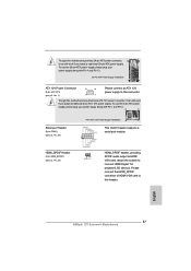
... the front USB port can receive the multi-direction infrared signals (top, down and front), which is only supported by some of ASRock motherboards. Please do not use the rear USB bracket to the USB_PWR USB 2.0 header (as below procedures for front USB only. Connect the...Please refer to below , pin 1-5) and the CIR header. Please refer to ASRock website for ASRock motherboard with most of the chassis on ASRock motherboard. USB 2.0 header (9-pin, black) CIR header (4-pin, gray) Step2. GND IRTX IRRX ATX+5VSB Install Multi-Angle CIR Receiver to the USB 2.0 header on the market. ...
... the front USB port can receive the multi-direction infrared signals (top, down and front), which is only supported by some of ASRock motherboards. Please do not use the rear USB bracket to the USB_PWR USB 2.0 header (as below procedures for front USB only. Connect the...Please refer to below , pin 1-5) and the CIR header. Please refer to ASRock website for ASRock motherboard with most of the chassis on ASRock motherboard. USB 2.0 header (9-pin, black) CIR header (4-pin, gray) Step2. GND IRTX IRRX ATX+5VSB Install Multi-Angle CIR Receiver to the USB 2.0 header on the market. ...
User Manual
Page 37
... one USB 3.0 header on the chassis must support HDA to MIC2_L. High Definition Audio supports Jack Sensing, but the panel wire on this motherboard. This USB 3.0 header can be used to the front panel audio header as below: A. Connect Mic_IN (MIC) to function correctly. B. Connect Audio_R (RIN... (GND) to install your system. 2. (9-pin USB6_7) (see p.13, No. 24) USB 3.0 Header (19-pin USB3_4_5) (see p.13 No. 27) 1 GND IRTX IRRX ATX+5VSB This header can support two USB 3.0 ports. Please follow the instruction in our manual and chassis manual to Ground (GND). C. D.
... one USB 3.0 header on the chassis must support HDA to MIC2_L. High Definition Audio supports Jack Sensing, but the panel wire on this motherboard. This USB 3.0 header can be used to the front panel audio header as below: A. Connect Mic_IN (MIC) to function correctly. B. Connect Audio_R (RIN... (GND) to install your system. 2. (9-pin USB6_7) (see p.13, No. 24) USB 3.0 Header (19-pin USB3_4_5) (see p.13 No. 27) 1 GND IRTX IRRX ATX+5VSB This header can support two USB 3.0 ports. Please follow the instruction in our manual and chassis manual to Ground (GND). C. D.
User Manual
Page 39
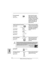
...header to indicate system power status. CPU Fan Connectors (4-pin CPU_FAN1) (see p.13, No. 8) 12 24 Please connect an ATX power supply to this motherboard, please connect it to Pin 1-3. Pin 1-3 Connected 3-Pin Fan Installation (3-pin CPU_FAN2) (see p.13, No. 5) GND +12V CPU_FAN_SPEED... ATX Power Connector (24-pin ATXPWR1) (see p.13, No. 3) FAN_SPEED_CONTROL CPU_FAN_SPEED +12V GND 1 2 3 4 Please connect the CPU fan ...
...header to indicate system power status. CPU Fan Connectors (4-pin CPU_FAN1) (see p.13, No. 8) 12 24 Please connect an ATX power supply to this motherboard, please connect it to Pin 1-3. Pin 1-3 Connected 3-Pin Fan Installation (3-pin CPU_FAN2) (see p.13, No. 5) GND +12V CPU_FAN_SPEED... ATX Power Connector (24-pin ATXPWR1) (see p.13, No. 3) FAN_SPEED_CONTROL CPU_FAN_SPEED +12V GND 1 2 3 4 Please connect the CPU fan ...
User Manual
Page 40
...13. 20-Pin ATX Power Supply Installation 1 13 ATX 12V Power Connector (8-pin ATX12V1) (see p.13, No. 1) 8 5 4 1 Please connect an ATX 12V power supply to this motherboard provides 8-pin ATX 12V power connector, it can still work if you adopt a traditional 4-pin ATX 12V power supply.... Though this connector. To use the 20-pin ATX power supply, please plug your power supply along...
...13. 20-Pin ATX Power Supply Installation 1 13 ATX 12V Power Connector (8-pin ATX12V1) (see p.13, No. 1) 8 5 4 1 Please connect an ATX 12V power supply to this motherboard provides 8-pin ATX 12V power connector, it can still work if you adopt a traditional 4-pin ATX 12V power supply.... Though this connector. To use the 20-pin ATX power supply, please plug your power supply along...

Quick Installation Guide
Page 2
... PWRBTN 1 HDLED RESET PWRBTN RSTBTN 12 13 14 31 30 29 28 27 26 25 24 23 22 21 20 19 18 17 16 15 1 ATX 12V Power Connector (ATX12V1) 21 Dr. Debug 2 1155-Pin CPU Socket 22 Chassis Fan Connector (CHA_FAN1) 3 CPU Fan Connector (CPU_FAN1) 23 SPI Flash Memory (64Mb... 2.0 x1 Slot (PCIE1, Black) 19 Power LED Header (PLED1) 38 Chassis Fan Connector (CHA_FAN2) 20 System Panel Header (PANEL1, Black) 39 Chassis Fan Connector (CHA_FAN3) 2 ASRock Z77 Extreme4 Motherboard English
... PWRBTN 1 HDLED RESET PWRBTN RSTBTN 12 13 14 31 30 29 28 27 26 25 24 23 22 21 20 19 18 17 16 15 1 ATX 12V Power Connector (ATX12V1) 21 Dr. Debug 2 1155-Pin CPU Socket 22 Chassis Fan Connector (CHA_FAN1) 3 CPU Fan Connector (CPU_FAN1) 23 SPI Flash Memory (64Mb... 2.0 x1 Slot (PCIE1, Black) 19 Power LED Header (PLED1) 38 Chassis Fan Connector (CHA_FAN2) 20 System Panel Header (PANEL1, Black) 39 Chassis Fan Connector (CHA_FAN3) 2 ASRock Z77 Extreme4 Motherboard English
Quick Installation Guide
Page 5
... may find the latest VGA cards and CPU support lists on ASRock website without notice. www.asrock.com/support/index.asp 1.1 Package Contents ASRock Z77 Extreme4 Motherboard (ATX Form Factor: 12.0-in x 8.6-in the Support CD. It delivers excellent performance with robust design conforming to ASRock's commitment to AHCI mode. To get better performance in Windows®...
... may find the latest VGA cards and CPU support lists on ASRock website without notice. www.asrock.com/support/index.asp 1.1 Package Contents ASRock Z77 Extreme4 Motherboard (ATX Form Factor: 12.0-in x 8.6-in the Support CD. It delivers excellent performance with robust design conforming to ASRock's commitment to AHCI mode. To get better performance in Windows®...

Quick Installation Guide
Page 6
ATX Form Factor: 12.0-in x 8.6-in Visuals: Intel® Quick... design (100% Japan-made high-quality Conductive Polymer Capacitors) - capacity of system memory: 32GB (see CAUTION 5) ASRock Z77 Extreme4 Motherboard English Supports NVIDIA® Quad SLITM and SLITM * Intel® HD Graphics Built-in LGA1155 Package - Pixel Shader...and Smart Connect Technology with processors which are GPU integrated. - Digi Power Design - 8 + 4 Power Phase Design - Intel® Z77 - Supports Intel® Extreme Memory Profile (XMP)1.3/1.2 - 2 x PCI Express 3.0 x16 slots (PCIE2/PCIE3: single at...
ATX Form Factor: 12.0-in x 8.6-in Visuals: Intel® Quick... design (100% Japan-made high-quality Conductive Polymer Capacitors) - capacity of system memory: 32GB (see CAUTION 5) ASRock Z77 Extreme4 Motherboard English Supports NVIDIA® Quad SLITM and SLITM * Intel® HD Graphics Built-in LGA1155 Package - Pixel Shader...and Smart Connect Technology with processors which are GPU integrated. - Digi Power Design - 8 + 4 Power Phase Design - Intel® Z77 - Supports Intel® Extreme Memory Profile (XMP)1.3/1.2 - 2 x PCI Express 3.0 x16 slots (PCIE2/PCIE3: single at...

Quick Installation Guide
Page 8
... "Plug and Play" - OEM - CPU/Chassis/Power FAN connector - 24 pin ATX power connector - 8 pin 12V power connector - SMBIOS 2.3.1 Support - ASRock Extreme Tuning Utility (AXTU) (see CAUTION 9) - Supports jumperfree - ASRock Instant Boot English 8 ASRock Z77 Extreme4 Motherboard Drivers, Utilities, AntiVirus Software (Trial Version), CyberLink MediaEspresso 6.5 Trial, ASRock MAGIX Multimedia Suite - Front panel audio connector - 3 x USB 2.0 headers (support 6 USB...
... "Plug and Play" - OEM - CPU/Chassis/Power FAN connector - 24 pin ATX power connector - 8 pin 12V power connector - SMBIOS 2.3.1 Support - ASRock Extreme Tuning Utility (AXTU) (see CAUTION 9) - Supports jumperfree - ASRock Instant Boot English 8 ASRock Z77 Extreme4 Motherboard Drivers, Utilities, AntiVirus Software (Trial Version), CyberLink MediaEspresso 6.5 Trial, ASRock MAGIX Multimedia Suite - Front panel audio connector - 3 x USB 2.0 headers (support 6 USB...

Quick Installation Guide
Page 13
... or change any component, ensure that the power is switched off or the power cord is an ATX form factor (12.0" x 8.6", 30.5 x 21.8 cm) motherboard. Make sure to do not touch the ICs. 4. Do not over -tighten the screws! Unplug ... the motherboard, study the configuration of the following precautions before touching any component, place it . 2. Before you uninstall any components. 2. To avoid damaging the motherboard's components due to static electricity, NEVER place your chassis to the motherboard, peripherals, and/or components. 13 ASRock Z77 Extreme4 Motherboard English...
... or change any component, ensure that the power is switched off or the power cord is an ATX form factor (12.0" x 8.6", 30.5 x 21.8 cm) motherboard. Make sure to do not touch the ICs. 4. Do not over -tighten the screws! Unplug ... the motherboard, study the configuration of the following precautions before touching any component, place it . 2. Before you uninstall any components. 2. To avoid damaging the motherboard's components due to static electricity, NEVER place your chassis to the motherboard, peripherals, and/or components. 13 ASRock Z77 Extreme4 Motherboard English...

Quick Installation Guide
Page 31
... below procedures for the motherboard support list: http://www.asrock.com 31 ASRock Z77 Extreme4 Motherboard 2.10 ASRock Smart Remote Installation Guide ASRock Smart Remote is only supported by some of ASRock motherboards. Step1. Multi-Angle CIR Receiver can support CIR function. Find the CIR header located next to the front USB port. GND IRTX IRRX ATX+5VSB Install Multi-Angle...
... below procedures for the motherboard support list: http://www.asrock.com 31 ASRock Z77 Extreme4 Motherboard 2.10 ASRock Smart Remote Installation Guide ASRock Smart Remote is only supported by some of ASRock motherboards. Step1. Multi-Angle CIR Receiver can support CIR function. Find the CIR header located next to the front USB port. GND IRTX IRRX ATX+5VSB Install Multi-Angle...
Quick Installation Guide
Page 34
... to the front panel audio header as below: A. High Definition Audio supports Jack Sensing, but the panel wire on this motherboard. This USB 3.0 header can be used to connect them for HD audio panel only. You don't need to connect the remote controller...GND IRTX IRRX ATX+5VSB This header can support two USB 3.0 ports. If you use AC'97 audio panel, please install it to install your system. 2. B. Connect Audio_R (RIN) to OUT2_R and Audio_L (LIN) to function correctly. MIC_RET and OUT_RET are for AC'97 audio panel. 34 ASRock Z77 Extreme4 Motherboard English
... to the front panel audio header as below: A. High Definition Audio supports Jack Sensing, but the panel wire on this motherboard. This USB 3.0 header can be used to connect them for HD audio panel only. You don't need to connect the remote controller...GND IRTX IRRX ATX+5VSB This header can support two USB 3.0 ports. If you use AC'97 audio panel, please install it to install your system. 2. B. Connect Audio_R (RIN) to OUT2_R and Audio_L (LIN) to function correctly. MIC_RET and OUT_RET are for AC'97 audio panel. 34 ASRock Z77 Extreme4 Motherboard English
Quick Installation Guide
Page 36
...Please connect the CPU fan cable to the connector and match the black wire to the ground pin. Though this connector. 1 13 36 ASRock Z77 Extreme4 Motherboard English The LED is on this header to indicate system power status. Pin 1-3 Connected 3-Pin Fan Installation (3-pin CPU_FAN2) (see p.2, No.... 5) GND +12V CPU_FAN_SPEED ATX Power Connector (24-pin ATXPWR1) (see p.2, No. 8) 12 24 Please connect an ATX power supply to this motherboard provides 4-Pin CPU fan (Quiet Fan) support, the 3-Pin CPU fan still can...
...Please connect the CPU fan cable to the connector and match the black wire to the ground pin. Though this connector. 1 13 36 ASRock Z77 Extreme4 Motherboard English The LED is on this header to indicate system power status. Pin 1-3 Connected 3-Pin Fan Installation (3-pin CPU_FAN2) (see p.2, No.... 5) GND +12V CPU_FAN_SPEED ATX Power Connector (24-pin ATXPWR1) (see p.2, No. 8) 12 24 Please connect an ATX power supply to this motherboard provides 4-Pin CPU fan (Quiet Fan) support, the 3-Pin CPU fan still can...
Quick Installation Guide
Page 37
... to HDMI VGA card, allows the system to connect HDMI Digital TV/ projector/LCD devices. English 37 ASRock Z77 Extreme4 Motherboard Though this motherboard provides 8-pin ATX 12V power connector, it can still work if you adopt a traditional 4-pin ATX 12V power supply. Please connect the HDMI_SPDIF connector of HDMI VGA card to this connector. Though this...
... to HDMI VGA card, allows the system to connect HDMI Digital TV/ projector/LCD devices. English 37 ASRock Z77 Extreme4 Motherboard Though this motherboard provides 8-pin ATX 12V power connector, it can still work if you adopt a traditional 4-pin ATX 12V power supply. Please connect the HDMI_SPDIF connector of HDMI VGA card to this connector. Though this...
Quick Installation Guide
Page 159
...; USB 3.0 USB 3.0 헤더는 2 개 의 USB 3.0 (5 핀 IR1) (2 30 (4 핀 CIR1) (2 27 (9 핀 HD_AUDIO1) (2 31 IRTX +5VSB DUMMY 1 GND IRRX 1 GND IRTX IRRX ATX+5VSB GND PRESENCE# MIC_RET OUT_RET 1 OUT2_L J_SENSE OUT2_R MIC2_R MIC2_L 159 ASRock Z77 Extreme4 Motherboard 한국어
...; USB 3.0 USB 3.0 헤더는 2 개 의 USB 3.0 (5 핀 IR1) (2 30 (4 핀 CIR1) (2 27 (9 핀 HD_AUDIO1) (2 31 IRTX +5VSB DUMMY 1 GND IRRX 1 GND IRTX IRRX ATX+5VSB GND PRESENCE# MIC_RET OUT_RET 1 OUT2_L J_SENSE OUT2_R MIC2_R MIC2_L 159 ASRock Z77 Extreme4 Motherboard 한국어
Quick Installation Guide
Page 162
...; CPU_FAN2) (2 5 GND +12V CPU_FAN_SPEED ATX (24 핀 ATXPWR1) (2 8 12 24 ATX 1 13 24 핀 ATX 12 24 종래의 20 핀 ATX 20 핀 ATX Pin 1 과 Pin 13 20 핀 ATX 1 13 ATX 12V (8 핀 ATX12V1) (2 1 8 5 4 1 ATX 12V 8- 핀 ATX 12V 4- 핀 ATX 12V 하여 4- 핀 ATX 1 과 핀 5 8 5 (9 핀 COM1) (2 28 4- 핀 ATX 12V 4 1 한 국 어 162 ASRock Z77 Extreme4 Motherboard
...; CPU_FAN2) (2 5 GND +12V CPU_FAN_SPEED ATX (24 핀 ATXPWR1) (2 8 12 24 ATX 1 13 24 핀 ATX 12 24 종래의 20 핀 ATX 20 핀 ATX Pin 1 과 Pin 13 20 핀 ATX 1 13 ATX 12V (8 핀 ATX12V1) (2 1 8 5 4 1 ATX 12V 8- 핀 ATX 12V 4- 핀 ATX 12V 하여 4- 핀 ATX 1 과 핀 5 8 5 (9 핀 COM1) (2 28 4- 핀 ATX 12V 4 1 한 국 어 162 ASRock Z77 Extreme4 Motherboard
Quick Installation Guide
Page 175
... FrontMic Windows® 7 / 7 64-bit / VistaTM / VistaTM 64-bit OS の場合 : 日本語 175 ASRock Z77 Extreme4 Motherboard USB 3.0 ヘッダ (19 ピン USB3_4_5) ページ 2 9 を参照 Vbus IntA_P4_SSRXIntA_P4_SSRX+ GND ...DUMMY 1 GND IRRX 4 ピン CIR1 27 を参照 1 GND IRTX IRRX ATX+5VSB 9 ピン HD_AUDIO1) ページ 2 31 を参照 GND PRESENCE# MIC_RET OUT_RET 1 OUT2_L J_SENSE OUT2_R MIC2_R MIC2_L ...
... FrontMic Windows® 7 / 7 64-bit / VistaTM / VistaTM 64-bit OS の場合 : 日本語 175 ASRock Z77 Extreme4 Motherboard USB 3.0 ヘッダ (19 ピン USB3_4_5) ページ 2 9 を参照 Vbus IntA_P4_SSRXIntA_P4_SSRX+ GND ...DUMMY 1 GND IRRX 4 ピン CIR1 27 を参照 1 GND IRTX IRRX ATX+5VSB 9 ピン HD_AUDIO1) ページ 2 31 を参照 GND PRESENCE# MIC_RET OUT_RET 1 OUT2_L J_SENSE OUT2_R MIC2_R MIC2_L ...
Quick Installation Guide
Page 177
... 1 2 3 4 4 ピン CPU 3 ピン CPU 3 ピン CPU CPU 1-3 1-3 3 (3 ピン CPU_FAN2) ページ 2 5 を参照 GND +12V CPU_FAN_SPEED 日本語 ATX 24 ピン ATXPWR1) ページ 2 8 を参照 12 24 ATX 1 13 177 ASRock Z77 Extreme4 Motherboard
... 1 2 3 4 4 ピン CPU 3 ピン CPU 3 ピン CPU CPU 1-3 1-3 3 (3 ピン CPU_FAN2) ページ 2 5 を参照 GND +12V CPU_FAN_SPEED 日本語 ATX 24 ピン ATXPWR1) ページ 2 8 を参照 12 24 ATX 1 13 177 ASRock Z77 Extreme4 Motherboard


