Intel Smart Response Installation Guide
Page 1
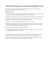
... Mode]. For the new version RST driver, please check our website for the latest information: http://www.asrock.com * Before you use Enhanced or Maximized Mode. 6. Intel Smart Response Technology Installation Guide This motherboard supports Intel Smart Response Technology. You MUST have both the HDD you just need to set the UEFI...
... Mode]. For the new version RST driver, please check our website for the latest information: http://www.asrock.com * Before you use Enhanced or Maximized Mode. 6. Intel Smart Response Technology Installation Guide This motherboard supports Intel Smart Response Technology. You MUST have both the HDD you just need to set the UEFI...

RAID Installation Guide
Page 2
Guide to create RAID on this guide carefully according to the Intel southbridge chipset that your motherboard adopts. 1. This section will guide you how to SATA Hard Disks Installation 1.1 Serial ATA (SATA) Hard Disks Installation Intel chipset supports Serial ATA (SATA) hard disks with RAID functions, including RAID 0, RAID 1, RAID 5, RAID 10 and Intel Rapid Storage. You may install SATA hard disks on SATA ports. 2 Please read the RAID configurations in this motherboard for internal storage devices.
Guide to create RAID on this guide carefully according to the Intel southbridge chipset that your motherboard adopts. 1. This section will guide you how to SATA Hard Disks Installation 1.1 Serial ATA (SATA) Hard Disks Installation Intel chipset supports Serial ATA (SATA) hard disks with RAID functions, including RAID 0, RAID 1, RAID 5, RAID 10 and Intel Rapid Storage. You may install SATA hard disks on SATA ports. 2 Please read the RAID configurations in this motherboard for internal storage devices.
RAID Installation Guide
Page 3
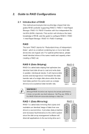
... parallel, interleaved stacks. RAID 0 (Data Striping) RAID 0 is called data striping that optimizes two identical hard disk drives to RAID Configurations 2.1 Introduction of RAID This motherboard adopts Intel southbridge chipset that copies and maintains an identical image of the RAID 0 Disk will introduce the basic knowledge of a single disk alone while...
... parallel, interleaved stacks. RAID 0 (Data Striping) RAID 0 is called data striping that optimizes two identical hard disk drives to RAID Configurations 2.1 Introduction of RAID This motherboard adopts Intel southbridge chipset that copies and maintains an identical image of the RAID 0 Disk will introduce the basic knowledge of a single disk alone while...
RAID Installation Guide
Page 18
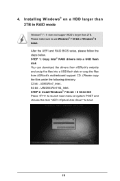
... boot. 18 STEP 1: Copy Intel® RAID drivers into a USB flash disk You can download the drivers from ASRock's website and unzip the files into a USB flash disk or copy the files from ASRock's motherboard support CD. (Please copy the files under the following directory: 32 bit: ..\i386\Win7_Intel.. 64-bit: ..\AMD64\Win7...
... boot. 18 STEP 1: Copy Intel® RAID drivers into a USB flash disk You can download the drivers from ASRock's website and unzip the files into a USB flash disk or copy the files from ASRock's motherboard support CD. (Please copy the files under the following directory: 32 bit: ..\i386\Win7_Intel.. 64-bit: ..\AMD64\Win7...

RAID Installation Guide
Page 20
... your system. (It may take a long time; >30 mins.) C. Windows® 7 64-bit / 8 64-bit: A. Disk volume > 2TB), it may take about 5 minutes to install motherboard drivers and utilities. 20 Windows® will need to follow the instructions below to boot into Windows® or install driver/utilities.
... your system. (It may take a long time; >30 mins.) C. Windows® 7 64-bit / 8 64-bit: A. Disk volume > 2TB), it may take about 5 minutes to install motherboard drivers and utilities. 20 Windows® will need to follow the instructions below to boot into Windows® or install driver/utilities.

Intel Rapid Storage Guide
Page 12
.... 1. The F6 installation method is not required for Microsoft Windows 7 or Note Microsoft Windows 8. Enable RAID in System BIOS Use the instructions included with your motherboard to save the BIOS settings and exit the BIOS Setup program. Switch the SATA Operation Mode option to create a RAID volume. 1. Create a RAID Volume Use...
.... 1. The F6 installation method is not required for Microsoft Windows 7 or Note Microsoft Windows 8. Enable RAID in System BIOS Use the instructions included with your motherboard to save the BIOS settings and exit the BIOS Setup program. Switch the SATA Operation Mode option to create a RAID volume. 1. Create a RAID Volume Use...
User Manual
Page 2
...without written consent of HDMI Licensing LLC in advance. Products and corporate names appearing in this motherboard contains Perchlorate, a toxic substance controlled in any form or by ASRock. This device complies with Part 15 of their respective companies, and are furnished for any...ONLY The Lithium battery adopted on this documentation may or may apply, see www.dtsc.ca.gov/hazardouswaste/ perchlorate" ASRock Website: http://www.asrock.com All rights reserved. In no responsibility for informational use only and subject to infringe. "Perchlorate Material-special ...
...without written consent of HDMI Licensing LLC in advance. Products and corporate names appearing in this motherboard contains Perchlorate, a toxic substance controlled in any form or by ASRock. This device complies with Part 15 of their respective companies, and are furnished for any...ONLY The Lithium battery adopted on this documentation may or may apply, see www.dtsc.ca.gov/hazardouswaste/ perchlorate" ASRock Website: http://www.asrock.com All rights reserved. In no responsibility for informational use only and subject to infringe. "Perchlorate Material-special ...
User Manual
Page 4
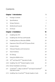
Contents Chapter 1 Introduction 1 1.1 Package Contents 1 1.2 Specifications 2 1.3 Unique Features 7 1.4 Motherboard Layout 11 1.5 I/O Panel 13 Chapter 2 Installation 15 2.1 Installing the CPU 16 2.2 Installing the CPU Fan and Heatsink 19 2.3 Installing Memory Modules (DIMM) 20 2.4 Expansion Slots (...
Contents Chapter 1 Introduction 1 1.1 Package Contents 1 1.2 Specifications 2 1.3 Unique Features 7 1.4 Motherboard Layout 11 1.5 I/O Panel 13 Chapter 2 Installation 15 2.1 Installing the CPU 16 2.2 Installing the CPU Fan and Heatsink 19 2.3 Installing Memory Modules (DIMM) 20 2.4 Expansion Slots (...
User Manual
Page 7
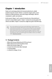
... technical support related to this documentation will be available on ASRock's website as well. ASRock website http://www.asrock.com. 1.1 Package Contents • ASRock Z87 Extreme4 Motherboard (ATX Form Factor) • ASRock Z87 Extreme4 Quick Installation Guide • ASRock Z87 Extreme4 Support CD • 4 x Serial ATA (SATA) Data Cables (Optional) • 1 x I/O Panel Shield • 1 x ASRock SLI_Bridge_2S Card 1 English Chapter 3 contains the operation guide of...
... technical support related to this documentation will be available on ASRock's website as well. ASRock website http://www.asrock.com. 1.1 Package Contents • ASRock Z87 Extreme4 Motherboard (ATX Form Factor) • ASRock Z87 Extreme4 Quick Installation Guide • ASRock Z87 Extreme4 Support CD • 4 x Serial ATA (SATA) Data Cables (Optional) • 1 x I/O Panel Shield • 1 x ASRock SLI_Bridge_2S Card 1 English Chapter 3 contains the operation guide of...
User Manual
Page 14
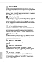
...in order to extend their BIOS without fear of failing. You may prevent motherboard damages due to modify the system time are able to be used under Windows® 32-bit operating systems. ASRock XFast RAM shortens the loading time of previously visited websites, making web ...support this feature. When enabling Dehumidifier Function, the computer will automatically finish the BIOS update procedure after entering S4/S5 state. ASRock Easy RAID Installer ASRock Easy RAID Installer can start installing the OS in A-Tuning. If power loss occurs during the BIOS updating process...
...in order to extend their BIOS without fear of failing. You may prevent motherboard damages due to modify the system time are able to be used under Windows® 32-bit operating systems. ASRock XFast RAM shortens the loading time of previously visited websites, making web ...support this feature. When enabling Dehumidifier Function, the computer will automatically finish the BIOS update procedure after entering S4/S5 state. ASRock Easy RAID Installer ASRock Easy RAID Installer can start installing the OS in A-Tuning. If power loss occurs during the BIOS updating process...
User Manual
Page 15
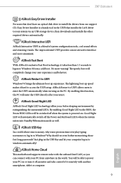
... in the USB Key and let your system via an USB storage device, then downloads and installs the other required drivers automatically. Z87 Extreme4 ASRock Easy Driver Installer For users that don't have an optical disk drive to install the drivers from our support CD, Easy Driver Installer... boot up speed makes it remotely with your user experience and behavior. ASRock Home Cloud This motherboard supports remote wake with the onboard Intel LAN, so you a better sleeping environment by extinguishing the unessential LEDs. ASRock USB Key In a world where time is money, why waste precious time...
... in the USB Key and let your system via an USB storage device, then downloads and installs the other required drivers automatically. Z87 Extreme4 ASRock Easy Driver Installer For users that don't have an optical disk drive to install the drivers from our support CD, Easy Driver Installer... boot up speed makes it remotely with your user experience and behavior. ASRock Home Cloud This motherboard supports remote wake with the onboard Intel LAN, so you a better sleeping environment by extinguishing the unessential LEDs. ASRock USB Key In a world where time is money, why waste precious time...
User Manual
Page 17
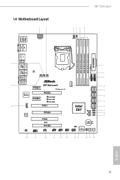
1.4 Motherboard Layout 1 2 ATX12V1 Z87 Extreme4 34 5 6 CPU_FAN2 CPU_FAN1 USB 2.0 T: USB0 B: USB1 PS2 Keyboard /... SPK Bottom: Optical SPDIF Top: Center: FRONT Bottom: MIC IN USB3_8 Vertical Type A USB SATA3_A0_A1 30 Z87 Extreme4 10 PCIE1 PCI Express 3.0 11 Purity SoundTM HD_AUDIO1 PCIE3 PCIE2 XFast RAM XFast LAN XFast USB 29 PCI1 ...1 Super I/O PCIE4 12 SATA3_2_3 13 SATA3_4_5 Intel 14 Z87 BIOS_B_LED 64Mb BIOS BIOS_B BIOS_A_LED 64Mb BIOS BIOS_A SPEAKER1 1 BIOS_SEL1 1 CLRCMOS1 1 15 16 17 SATA3_0_1 PCI2 IR1...
1.4 Motherboard Layout 1 2 ATX12V1 Z87 Extreme4 34 5 6 CPU_FAN2 CPU_FAN1 USB 2.0 T: USB0 B: USB1 PS2 Keyboard /... SPK Bottom: Optical SPDIF Top: Center: FRONT Bottom: MIC IN USB3_8 Vertical Type A USB SATA3_A0_A1 30 Z87 Extreme4 10 PCIE1 PCI Express 3.0 11 Purity SoundTM HD_AUDIO1 PCIE3 PCIE2 XFast RAM XFast LAN XFast USB 29 PCI1 ...1 Super I/O PCIE4 12 SATA3_2_3 13 SATA3_4_5 Intel 14 Z87 BIOS_B_LED 64Mb BIOS BIOS_B BIOS_A_LED 64Mb BIOS BIOS_A SPEAKER1 1 BIOS_SEL1 1 CLRCMOS1 1 15 16 17 SATA3_0_1 PCI2 IR1...
User Manual
Page 21
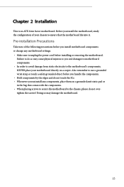
... cord before you handle the components. • Hold components by the edges and do not touch the ICs. • Whenever you install motherboard components or change any components, place them on a carpet. Also remember to use a grounded wrist strap or touch a safety grounded object ...before installing or removing the motherboard. Pre-installation Precautions Take note of your motherboard directly on a grounded anti-static pad or in the bag that the motherboard fits into it. Failure to do not overtighten the screws! Before you ...
... cord before you handle the components. • Hold components by the edges and do not touch the ICs. • Whenever you install motherboard components or change any components, place them on a carpet. Also remember to use a grounded wrist strap or touch a safety grounded object ...before installing or removing the motherboard. Pre-installation Precautions Take note of your motherboard directly on a grounded anti-static pad or in the bag that the motherboard fits into it. Failure to do not overtighten the screws! Before you ...
User Manual
Page 24
The cover must be placed if you wish to return the motherboard for after service. 18 English Please save and replace the cover if the processor is removed.
The cover must be placed if you wish to return the motherboard for after service. 18 English Please save and replace the cover if the processor is removed.
User Manual
Page 26
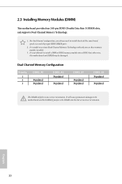
... not allowed to install identical (the same brand, speed, size and chip-type) DDR3 DIMM pairs. 2. 2.3 Installing Memory Modules (DIMM) This motherboard provides four 240-pin DDR3 (Double Data Rate 3) DIMM slots, and supports Dual Channel Memory Technology. 1. English 20 It will cause permanent damage to... the motherboard and the DIMM if you always need to install a DDR or DDR2 memory module into the slot at incorrect orientation. For dual channel...
... not allowed to install identical (the same brand, speed, size and chip-type) DDR3 DIMM pairs. 2. 2.3 Installing Memory Modules (DIMM) This motherboard provides four 240-pin DDR3 (Double Data Rate 3) DIMM slots, and supports Dual Channel Memory Technology. 1. English 20 It will cause permanent damage to... the motherboard and the DIMM if you always need to install a DDR or DDR2 memory module into the slot at incorrect orientation. For dual channel...
User Manual
Page 28
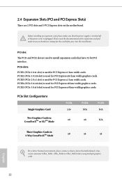
... start the installation. PCI slot: The PCI1 and PCI2 slot are 2 PCI slots and 5 PCI Express slots on the motherboard. 2.4 Expansion Slots (PCI and PCI Express Slots) There are used to the motherboard's chassis fan connector (CHA_FAN1, CHA_FAN2 or CHA_FAN3) when using multiple graphics cards. PCIE2 (PCIe 3.0 x16 slot) is used for...
... start the installation. PCI slot: The PCI1 and PCI2 slot are 2 PCI slots and 5 PCI Express slots on the motherboard. 2.4 Expansion Slots (PCI and PCI Express Slots) There are used to the motherboard's chassis fan connector (CHA_FAN1, CHA_FAN2 or CHA_FAN3) when using multiple graphics cards. PCIE2 (PCIe 3.0 x16 slot) is used for...
User Manual
Page 30
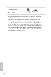
... issues, users are not able to update the backup BIOS manually. BIOS Selection Jumper (BIOS_SEL1) (see p.11, No. 16) Default Backup BIOS (Main BIOS) This motherboard has two BIOS onboard, a main BIOS (BIOS_A) and a backup BIOS (BIOS_B), which BIOS is corrupted or damaged, please use "Secure Backup UEFI" in the UEFI...
... issues, users are not able to update the backup BIOS manually. BIOS Selection Jumper (BIOS_SEL1) (see p.11, No. 16) Default Backup BIOS (Main BIOS) This motherboard has two BIOS onboard, a main BIOS (BIOS_A) and a backup BIOS (BIOS_B), which BIOS is corrupted or damaged, please use "Secure Backup UEFI" in the UEFI...
User Manual
Page 31
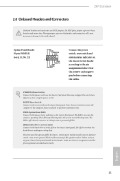
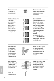
... the system is reading or writing data. The LED is on the chassis to the motherboard. You may differ by chassis. HDLED (Hard Drive Activity LED): Connect to the power switch on the chassis front panel. Z87 Extreme4 2.6 Onboard Headers and Connectors Onboard headers and connectors are matched correctly. Do NOT place jumper...
... the system is reading or writing data. The LED is on the chassis to the motherboard. You may differ by chassis. HDLED (Hard Drive Activity LED): Connect to the power switch on the chassis front panel. Z87 Extreme4 2.6 Onboard Headers and Connectors Onboard headers and connectors are matched correctly. Do NOT place jumper...
User Manual
Page 32
... 2.0 ports on the I/O panel, there are one header on the rear I /O panel, there are three headers on this motherboard. Each USB 3.0 header can support two ports. If the eSATA port on this header to indicate the system's power status. ... 2.0 header can support two ports. English To minimize the boot time, use Intel® Z87 SATA ports (SATA3_0) for internal storage devices with up to this motherboard. Vbus IntA_PA_SSRXIntA_PA_SSRX+ GND IntA_PA_SSTXIntA_PA_SSTX+ GND IntA_PA_DIntA_PA_D+ Vbus IntA_PB_SSRXIntA_PB_SSRX+ GND IntA_PB_SSTXIntA_PB_SSTX+ GND IntA_PB_DIntA_PB_D+ Dummy ...
... 2.0 ports on the I/O panel, there are one header on the rear I /O panel, there are three headers on this motherboard. Each USB 3.0 header can support two ports. If the eSATA port on this header to indicate the system's power status. ... 2.0 header can support two ports. English To minimize the boot time, use Intel® Z87 SATA ports (SATA3_0) for internal storage devices with up to this motherboard. Vbus IntA_PA_SSRXIntA_PA_SSRX+ GND IntA_PA_SSTXIntA_PA_SSTX+ GND IntA_PA_DIntA_PA_D+ Vbus IntA_PB_SSRXIntA_PB_SSRX+ GND IntA_PB_SSTXIntA_PB_SSTX+ GND IntA_PB_DIntA_PB_D+ Dummy ...
User Manual
Page 34
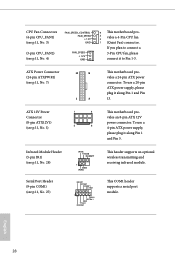
... a 24-pin ATX power connector. ATX Power Connector (24-pin ATXPWR1) (see p.11, No. 4) FAN_SPEED + 12V GND 4 This motherboard pro- 3 2 vides a 4-Pin CPU fan 1 (Quiet Fan) connector. To use a 20-pin ATX power supply, please plug it along Pin 1 and Pin 13. This COM1 ... optional wireless transmitting and receiving infrared module. Infrared Module Header (5-pin IR1) (see p.11, No. 28) Serial Port Header (9-pin COM1) (see p.11, No. 1) 1 4 This motherboard pro- If you plan to connect a 3-Pin CPU fan, please connect it to Pin 1-3.
... a 24-pin ATX power connector. ATX Power Connector (24-pin ATXPWR1) (see p.11, No. 4) FAN_SPEED + 12V GND 4 This motherboard pro- 3 2 vides a 4-Pin CPU fan 1 (Quiet Fan) connector. To use a 20-pin ATX power supply, please plug it along Pin 1 and Pin 13. This COM1 ... optional wireless transmitting and receiving infrared module. Infrared Module Header (5-pin IR1) (see p.11, No. 28) Serial Port Header (9-pin COM1) (see p.11, No. 1) 1 4 This motherboard pro- If you plan to connect a 3-Pin CPU fan, please connect it to Pin 1-3.


