Intel Smart Response Installation Guide
Page 1
... "Enable Acceleration" button on the GUI panel. 5. For the new version RST driver, please check our website for the latest information: http://www.asrock.com * Before you intend to a RAID mode system, then install all performance testing, chose "Maximized" mode. 7. It is not necessary to ... Intel® will refresh to build RAID 0 or RAID 1 in system at this point! 3. Intel Smart Response Technology Installation Guide This motherboard supports Intel Smart Response Technology. Once open RST GUI from either Start Menu or by step instructions below. You MUST have both the HDD you...
... "Enable Acceleration" button on the GUI panel. 5. For the new version RST driver, please check our website for the latest information: http://www.asrock.com * Before you intend to a RAID mode system, then install all performance testing, chose "Maximized" mode. 7. It is not necessary to ... Intel® will refresh to build RAID 0 or RAID 1 in system at this point! 3. Intel Smart Response Technology Installation Guide This motherboard supports Intel Smart Response Technology. Once open RST GUI from either Start Menu or by step instructions below. You MUST have both the HDD you...

RAID Installation Guide
Page 2
You may install SATA hard disks on this guide carefully according to create RAID on SATA ports. 2 This section will guide you how to the Intel southbridge chipset that your motherboard adopts. Please read the RAID configurations in this motherboard for internal storage devices. Guide to SATA Hard Disks Installation 1.1 Serial ATA (SATA) Hard Disks Installation Intel chipset supports Serial ATA (SATA) hard disks with RAID functions, including RAID 0, RAID 1, RAID 5, RAID 10 and Intel Rapid Storage. 1.
You may install SATA hard disks on this guide carefully according to create RAID on SATA ports. 2 This section will guide you how to the Intel southbridge chipset that your motherboard adopts. Please read the RAID configurations in this motherboard for internal storage devices. Guide to SATA Hard Disks Installation 1.1 Serial ATA (SATA) Hard Disks Installation Intel chipset supports Serial ATA (SATA) hard disks with RAID functions, including RAID 0, RAID 1, RAID 5, RAID 10 and Intel Rapid Storage. 1.
RAID Installation Guide
Page 3
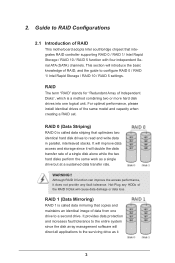
RAID 0 (Data Striping) RAID 0 is called data mirroring that copies and maintains an identical image of RAID This motherboard adopts Intel southbridge chipset that optimizes two identical hard disk drives to configure RAID 0 / RAID 1/ Intel Rapid Storage / RAID 10 / RAID 5 settings. WARNING!! This section ...
RAID 0 (Data Striping) RAID 0 is called data mirroring that copies and maintains an identical image of RAID This motherboard adopts Intel southbridge chipset that optimizes two identical hard disk drives to configure RAID 0 / RAID 1/ Intel Rapid Storage / RAID 10 / RAID 5 settings. WARNING!! This section ...
RAID Installation Guide
Page 18
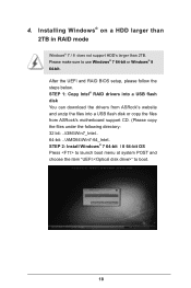
...; 8 64-bit. STEP 1: Copy Intel® RAID drivers into a USB flash disk You can download the drivers from ASRock's website and unzip the files into a USB flash disk or copy the files from ASRock's motherboard support CD. (Please copy the files under the following directory: 32 bit: ..\i386\Win7_Intel.. 64-bit: ..\AMD64\Win7...
...; 8 64-bit. STEP 1: Copy Intel® RAID drivers into a USB flash disk You can download the drivers from ASRock's website and unzip the files into a USB flash disk or copy the files from ASRock's motherboard support CD. (Please copy the files under the following directory: 32 bit: ..\i386\Win7_Intel.. 64-bit: ..\AMD64\Win7...

RAID Installation Guide
Page 20
... time to fix this problem. Please start to reboot.) D. Windows® 7 64-bit / 8 64-bit: A. Disk volume > 2TB), it may take about 5 minutes to install motherboard drivers and utilities. 20 Reboot your system. (It may take a long time; >30 mins.) C.
... time to fix this problem. Please start to reboot.) D. Windows® 7 64-bit / 8 64-bit: A. Disk volume > 2TB), it may take about 5 minutes to install motherboard drivers and utilities. 20 Reboot your system. (It may take a long time; >30 mins.) C.

Intel Rapid Storage Guide
Page 12
... keys to select the strip size and press Enter. 5. When finished press Enter. 12 Enable RAID in System BIOS Use the instructions included with your motherboard to save the BIOS settings and exit the BIOS Setup program. When the Intel Rapid Storage Technology option ROM status screen appears during operating system...
... keys to select the strip size and press Enter. 5. When finished press Enter. 12 Enable RAID in System BIOS Use the instructions included with your motherboard to save the BIOS settings and exit the BIOS Setup program. When the Intel Rapid Storage Technology option ROM status screen appears during operating system...

User Manual
Page 2
... is subject to the contents of this documentation, ASRock does not provide warranty of any errors or omissions...interruption of business and the like), even if ASRock has been advised of the possibility of HDMI...ASRock Website: http://www.asrock.com ASRock assumes no event shall ASRock, its directors, officers, employees, or agents be registered trademarks or copyrights of ASRock... Best Management Practices (BMP) regulations passed by ASRock. With respect to the following two conditions: ... 1.0 Published May 2013 Copyright©2013 ASRock INC. All rights reserved. In no responsibility...
... is subject to the contents of this documentation, ASRock does not provide warranty of any errors or omissions...interruption of business and the like), even if ASRock has been advised of the possibility of HDMI...ASRock Website: http://www.asrock.com ASRock assumes no event shall ASRock, its directors, officers, employees, or agents be registered trademarks or copyrights of ASRock... Best Management Practices (BMP) regulations passed by ASRock. With respect to the following two conditions: ... 1.0 Published May 2013 Copyright©2013 ASRock INC. All rights reserved. In no responsibility...

User Manual
Page 3
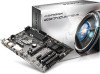
Contents Chapter 1 Introduction 1 1.1 Package Contents 1 1.2 Specifications 2 1.3 Unique Features 6 1.4 Motherboard Layout 10 1.5 I/O Panel 12 Chapter 2 Installation 14 2.1 Installing the CPU 15 2.2 Installing the CPU Fan and Heatsink 18 2.3 Installing Memory Modules (DIMM) 19 2.4 Expansion Slots (...
Contents Chapter 1 Introduction 1 1.1 Package Contents 1 1.2 Specifications 2 1.3 Unique Features 6 1.4 Motherboard Layout 10 1.5 I/O Panel 12 Chapter 2 Installation 14 2.1 Installing the CPU 15 2.2 Installing the CPU Fan and Heatsink 18 2.3 Installing Memory Modules (DIMM) 19 2.4 Expansion Slots (...
User Manual
Page 5
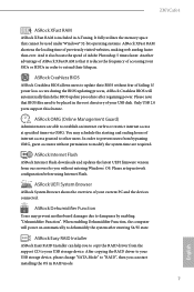
... of the software and utilities. If you are using. In case any modifications of the motherboard and step-by-step installation guides. ASRock website http://www.asrock.com. 1.1 Package Contents • ASRock Z87iCafe4 Motherboard (ATX Form Factor) • ASRock Z87iCafe4 Quick Installation Guide • ASRock Z87iCafe4 Support CD • 2 x Serial ATA (SATA) Data Cables (Optional) • 1 x I/O Panel Shield 1 English Chapter...
... of the software and utilities. If you are using. In case any modifications of the motherboard and step-by-step installation guides. ASRock website http://www.asrock.com. 1.1 Package Contents • ASRock Z87iCafe4 Motherboard (ATX Form Factor) • ASRock Z87iCafe4 Quick Installation Guide • ASRock Z87iCafe4 Support CD • 2 x Serial ATA (SATA) Data Cables (Optional) • 1 x I/O Panel Shield 1 English Chapter...
User Manual
Page 11
... If power loss occurs during the BIOS updating process, ASRock Crashless BIOS will power on automatically to your current PC and the devices connected. You may prevent motherboard damages due to update their lifespan. ASRock Dehumidifier Function Users may schedule the starting and ending hours...USB disk. When enabling Dehumidifier Function, the computer will automatically finish the BIOS update procedure after entering S4/S5 state. Z87iCafe4 ASRock XFast RAM ASRock XFast RAM is that it also boosts the speed of Adobe Photoshop 5 times faster. In order to establish an ...
... If power loss occurs during the BIOS updating process, ASRock Crashless BIOS will power on automatically to your current PC and the devices connected. You may prevent motherboard damages due to update their lifespan. ASRock Dehumidifier Function Users may schedule the starting and ending hours...USB disk. When enabling Dehumidifier Function, the computer will automatically finish the BIOS update procedure after entering S4/S5 state. Z87iCafe4 ASRock XFast RAM ASRock XFast RAM is that it also boosts the speed of Adobe Photoshop 5 times faster. In order to establish an ...

User Manual
Page 12
...to windows automatically! 8 English By enabling Good Night LED in to log in ACPI S5 mode)! The lightning boot up experience. This motherboard also provides a free 3.5mm audio cable (optional) that ensures users the most convenient computing environment. Why should we even bother memorizing ...from the portable audio devices, such like MP3 player or mobile phone to access the UEFI setup. ASRock Restart to UEFI allows users to Windows? ASRock Good Night LED ASRock Good Night LED technology offers you restart. By enabling this function, the PC will completely change your ...
...to windows automatically! 8 English By enabling Good Night LED in to log in ACPI S5 mode)! The lightning boot up experience. This motherboard also provides a free 3.5mm audio cable (optional) that ensures users the most convenient computing environment. Why should we even bother memorizing ...from the portable audio devices, such like MP3 player or mobile phone to access the UEFI setup. ASRock Restart to UEFI allows users to Windows? ASRock Good Night LED ASRock Good Night LED technology offers you restart. By enabling this function, the PC will completely change your ...

User Manual
Page 14
1.4 Motherboard Layout 1 2 3 4 PS2 Mouse PS2 Keyboard PWR_FAN1 ATX12V1 CPU_FAN1 CPU_FAN2 56 DVI1 VGA1 DDR3_A1 (64 bit, 240-pin module) DDR3_A2 (64 bit, 240-pin module) DDR3_B1 (... Top: Center: Bottom: MIC IN Audio CODEC CLRCMOS1 1 CMOS Battery X Fast RAM 26 PCIE1 X Fast USB X Fast LAN PCIE2 7 USB3_2_3 1 8 Front USB 3.0 SPEAKER1 PCI Express 3.0 9 1 Z87iCafe4 Super I/O PCIE3 PCI1 Intel Z87 SATA_5 SATA_6 64Mb BIOS 10 11 12 SATA_4 SATA_3 25 IR1 1 HD_AUDIO1 1 1 COM1 1 LPT1 PCI2 RoHS PCI3 USB4_5 1 USB6_7 1 CHA_FAN2...
1.4 Motherboard Layout 1 2 3 4 PS2 Mouse PS2 Keyboard PWR_FAN1 ATX12V1 CPU_FAN1 CPU_FAN2 56 DVI1 VGA1 DDR3_A1 (64 bit, 240-pin module) DDR3_A2 (64 bit, 240-pin module) DDR3_B1 (... Top: Center: Bottom: MIC IN Audio CODEC CLRCMOS1 1 CMOS Battery X Fast RAM 26 PCIE1 X Fast USB X Fast LAN PCIE2 7 USB3_2_3 1 8 Front USB 3.0 SPEAKER1 PCI Express 3.0 9 1 Z87iCafe4 Super I/O PCIE3 PCI1 Intel Z87 SATA_5 SATA_6 64Mb BIOS 10 11 12 SATA_4 SATA_3 25 IR1 1 HD_AUDIO1 1 1 COM1 1 LPT1 PCI2 RoHS PCI3 USB4_5 1 USB6_7 1 CHA_FAN2...

User Manual
Page 18
...ICs. • Whenever you uninstall any motherboard settings. • Make sure to unplug the power cord before you and damages to motherboard components. • In order to avoid damage from static electricity to the motherboard's components, NEVER place your chassis to ... placing screws to secure the motherboard to do not overtighten the screws! Before you install the motherboard, study the configuration of the following precautions before installing or removing the motherboard. Doing so may cause physical injuries to you install motherboard components or change any components...
...ICs. • Whenever you uninstall any motherboard settings. • Make sure to unplug the power cord before you and damages to motherboard components. • In order to avoid damage from static electricity to the motherboard's components, NEVER place your chassis to ... placing screws to secure the motherboard to do not overtighten the screws! Before you install the motherboard, study the configuration of the following precautions before installing or removing the motherboard. Doing so may cause physical injuries to you install motherboard components or change any components...

User Manual
Page 21
The cover must be placed if you wish to return the motherboard for after service. 17 English Z87iCafe4 Please save and replace the cover if the processor is removed.
The cover must be placed if you wish to return the motherboard for after service. 17 English Z87iCafe4 Please save and replace the cover if the processor is removed.

User Manual
Page 23
... Populated Populated DDR3_B1 Populated Populated DDR3_B2 Populated Populated The DIMM only fits in one or three memory module installed. 3. otherwise, this motherboard and DIMM may be damaged. It will cause permanent damage to activate Dual Channel Memory Technology with only one correct orientation. It ...is not allowed to install identical (the same brand, speed, size and chip-type) DDR3 DIMM pairs. 2. Z87iCafe4 2.3 Installing Memory Modules (DIMM) This motherboard provides four 240-pin DDR3 (Double Data Rate 3) DIMM slots, and supports Dual Channel Memory Technology. 1.
... Populated Populated DDR3_B1 Populated Populated DDR3_B2 Populated Populated The DIMM only fits in one or three memory module installed. 3. otherwise, this motherboard and DIMM may be damaged. It will cause permanent damage to activate Dual Channel Memory Technology with only one correct orientation. It ...is not allowed to install identical (the same brand, speed, size and chip-type) DDR3 DIMM pairs. 2. Z87iCafe4 2.3 Installing Memory Modules (DIMM) This motherboard provides four 240-pin DDR3 (Double Data Rate 3) DIMM slots, and supports Dual Channel Memory Technology. 1.

User Manual
Page 25
PCI slots: The PCI1, PCI2 and PCI3 slots are 3 PCI slots and 3 PCI Express slots on the motherboard. Before installing an expansion card, please make necessary hardware settings for the card before you start the installation. Please read the documentation of the expansion ...card and make sure that have 32-bit PCI interface. PCIE3 (PCIe 2.0 x1 slot) is unplugged. Z87iCafe4 2.4 Expansion Slots (PCI and PCI Express Slots) There are used to install expansion cards that the power supply is switched off or the power cord...
PCI slots: The PCI1, PCI2 and PCI3 slots are 3 PCI slots and 3 PCI Express slots on the motherboard. Before installing an expansion card, please make necessary hardware settings for the card before you start the installation. Please read the documentation of the expansion ...card and make sure that have 32-bit PCI interface. PCIE3 (PCIe 2.0 x1 slot) is unplugged. Z87iCafe4 2.4 Expansion Slots (PCI and PCI Express Slots) There are used to install expansion cards that the power supply is switched off or the power cord...

User Manual
Page 27
Z87iCafe4 2.6 Onboard Headers and Connectors Onboard headers and connectors are matched correctly. System Panel Header (9-pin PANEL1) (see p.10, No. 17) PLED+ PLEDPWRBTN# GND 1 GND RESET# ... to the power switch on the chassis front panel. Press the reset switch to restart the computer if the computer freezes and fails to the motherboard. The front panel design may configure the way to turn off your chassis front panel module to this header according to this header, make sure...
Z87iCafe4 2.6 Onboard Headers and Connectors Onboard headers and connectors are matched correctly. System Panel Header (9-pin PANEL1) (see p.10, No. 17) PLED+ PLEDPWRBTN# GND 1 GND RESET# ... to the power switch on the chassis front panel. Press the reset switch to restart the computer if the computer freezes and fails to the motherboard. The front panel design may configure the way to turn off your chassis front panel module to this header according to this header, make sure...

User Manual
Page 28
...(see p.10, No. 21) (9-pin USB6_7) (see p.10, No. 12) SATA_1 SATA_3 SATA_5 SATA_2 SATA_4 SATA_6 Please connect the chassis power LED to this motherboard. Power LED Header (3-pin PLED1) (see p.10, No. 8) Vbus IntA_PA_SSRXIntA_PA_SSRX+ GND IntA_PA_SSTXIntA_PA_SSTX+ GND IntA_PA_DIntA_PA_D+ Vbus IntA_PB_SSRXIntA_PB_SSRX+ GND IntA_PB_SSTXIntA_PB_SSTX+ GND IntA_PB_DIntA_PB_D+ Dummy 1 ..., No. 20) USB_PWR PP+ GND DUMMY 1 GND P+ PUSB_PWR Besides two USB 2.0 ports on the I /O panel, there is one header on this motherboard. USB 3.0 Header (19-pin USB3_2_3) (see p.10, No. 16) 1 PLED-
...(see p.10, No. 21) (9-pin USB6_7) (see p.10, No. 12) SATA_1 SATA_3 SATA_5 SATA_2 SATA_4 SATA_6 Please connect the chassis power LED to this motherboard. Power LED Header (3-pin PLED1) (see p.10, No. 8) Vbus IntA_PA_SSRXIntA_PA_SSRX+ GND IntA_PA_SSTXIntA_PA_SSTX+ GND IntA_PA_DIntA_PA_D+ Vbus IntA_PB_SSRXIntA_PB_SSRX+ GND IntA_PB_SSTXIntA_PB_SSTX+ GND IntA_PB_DIntA_PB_D+ Dummy 1 ..., No. 20) USB_PWR PP+ GND DUMMY 1 GND P+ PUSB_PWR Besides two USB 2.0 ports on the I /O panel, there is one header on this motherboard. USB 3.0 Header (19-pin USB3_2_3) (see p.10, No. 16) 1 PLED-

User Manual
Page 30
...CPU fan, please connect it along Pin 1 and Pin 13. This COM1 header supports a serial port module. 26 English This motherboard provides an 8-pin ATX 12V power connector. This header supports an optional wireless transmitting and receiving infrared module. ATX Power Connector ... (5-pin IR1) (see p.10, No. 25) Serial Port Header (9-pin COM1) (see p.10, No. 4) FAN_SPEED_CONTROL CPU_FAN_SPEED +12V GND GND +12V CPU_FAN_SPEED This motherboard provides a 4-Pin CPU fan (Quiet Fan) connector. (3-pin PWR_FAN1) (see p.10, No. 1) CPU Fan Connectors (4-pin CPU_FAN1) (see p.10, No. 3)...
...CPU fan, please connect it along Pin 1 and Pin 13. This COM1 header supports a serial port module. 26 English This motherboard provides an 8-pin ATX 12V power connector. This header supports an optional wireless transmitting and receiving infrared module. ATX Power Connector ... (5-pin IR1) (see p.10, No. 25) Serial Port Header (9-pin COM1) (see p.10, No. 4) FAN_SPEED_CONTROL CPU_FAN_SPEED +12V GND GND +12V CPU_FAN_SPEED This motherboard provides a 4-Pin CPU fan (Quiet Fan) connector. (3-pin PWR_FAN1) (see p.10, No. 1) CPU Fan Connectors (4-pin CPU_FAN1) (see p.10, No. 3)...
User Manual
Page 32
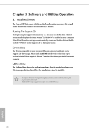
....com/kb/2720599/en-us 28 English Chapter 3 Software and Utilities Operation 3.1 Installing Drivers The Support CD that comes with the motherboard contains necessary drivers and useful utilities that the motherboard supports. Drivers Menu The drivers compatible to your system will be auto-detected and listed on a specific item then follow the... and double click on the file "ASRSETUP.EXE" in your CD-ROM drive. Utilities Menu The Utilities Menu shows the application software that enhance the motherboard's features. Therefore, the drivers you install can work properly.
....com/kb/2720599/en-us 28 English Chapter 3 Software and Utilities Operation 3.1 Installing Drivers The Support CD that comes with the motherboard contains necessary drivers and useful utilities that the motherboard supports. Drivers Menu The drivers compatible to your system will be auto-detected and listed on a specific item then follow the... and double click on the file "ASRSETUP.EXE" in your CD-ROM drive. Utilities Menu The Utilities Menu shows the application software that enhance the motherboard's features. Therefore, the drivers you install can work properly.

