Service Guide
Page 8
... Information 54 Before You Begin 54 Disassembly Procedure Flowchart 55 Disassembly Procedure 57 Removing the Battery Pack 57 Removing the HDD Module 57 Removing the RAM Module/Mini PCI Card/Thermal Module/CPU 58 Removing the ODD Module 60 Removing the LCD Module from the Main Unit 61 Removing the Keyboard...
... Information 54 Before You Begin 54 Disassembly Procedure Flowchart 55 Disassembly Procedure 57 Removing the Battery Pack 57 Removing the HDD Module 57 Removing the RAM Module/Mini PCI Card/Thermal Module/CPU 58 Removing the ODD Module 60 Removing the LCD Module from the Main Unit 61 Removing the Keyboard...
Service Guide
Page 41
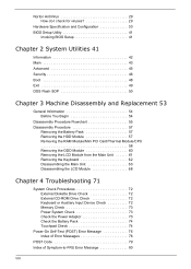
...System Memory Item Chip Feature VGA Item Chip Features PCMCIA Item PCMCIA controller Features Description • Acer UI support • Multi-boot support • 1MB flash RIOM for system BIOS • Suspend to RAM (S3) / Disk (S4) • Various hot keys for system control • Support ...boot option: HDD/Removable device (media bay device)/all USB ports • Support protocols: SMBIOS 2.3, PCI2.2, WFM2.0 • ACPI 2.0/3.0 compliance with Intel Speedstep support C1, C2, C3, C4, S3 and S4 for mobile ...
...System Memory Item Chip Feature VGA Item Chip Features PCMCIA Item PCMCIA controller Features Description • Acer UI support • Multi-boot support • 1MB flash RIOM for system BIOS • Suspend to RAM (S3) / Disk (S4) • Various hot keys for system control • Support ...boot option: HDD/Removable device (media bay device)/all USB ports • Support protocols: SMBIOS 2.3, PCI2.2, WFM2.0 • ACPI 2.0/3.0 compliance with Intel Speedstep support C1, C2, C3, C4, S3 and S4 for mobile ...
Service Guide
Page 49
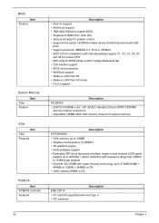
... CD, CD extra, I-Trax CD and UDF DVD-ROM, DVD-Video, DVDAudio, DVD-R single/multi border, DVD+R single/multi session, DVD-RW, DVD+RW, DVD-RAM Load: manual load/DC brushless motor system Max. 1500mA +5V +/- 5% (operating) Fan True Value Table Fan Fan off Speed 1 Speed 2 Speed 3 Speed 4 Speed 5 dBA 24...
... CD, CD extra, I-Trax CD and UDF DVD-ROM, DVD-Video, DVDAudio, DVD-R single/multi border, DVD+R single/multi session, DVD-RW, DVD+RW, DVD-RAM Load: manual load/DC brushless motor system Max. 1500mA +5V +/- 5% (operating) Fan True Value Table Fan Fan off Speed 1 Speed 2 Speed 3 Speed 4 Speed 5 dBA 24...
Service Guide
Page 57
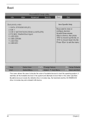
... and attempts to move it down the list. PhoenixBIOS Setup Utility Main Advanced Security Boot Exit Boot priority order: 1: SATA: ST9120821AS-(S1) 2: IDE 1: 3: IDE 0: MATSHITADVD-RAM UJ-845S-(PM) 4: PCI BEV: Realtek Boot Agent 5: USB HDD: 6: USB CDROM: 7: USB FDD: 8: USB KEY: Item Specific Help Keys used to view or configure...
... and attempts to move it down the list. PhoenixBIOS Setup Utility Main Advanced Security Boot Exit Boot priority order: 1: SATA: ST9120821AS-(S1) 2: IDE 1: 3: IDE 0: MATSHITADVD-RAM UJ-845S-(PM) 4: PCI BEV: Realtek Boot Agent 5: USB HDD: 6: USB CDROM: 7: USB FDD: 8: USB KEY: Item Specific Help Keys used to view or configure...
Service Guide
Page 67
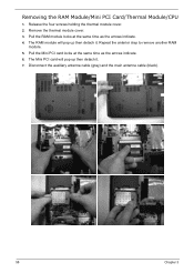
Pull the RAM module locks at the same time as the arrows indicate. 4. Disconnect the auxiliary antenna cable (gray) and the main antenna cable (black). 58 Chapter 3 Removing the RAM Module/Mini PCI Card/Thermal Module/CPU 1. The RAM module will pop up then detach it . 7. The Mini PCI card will pop up then detach it . Release the four screws holding the thermal module cover. 2. Repeat the anterior step to remove another RAM module. 5. Pull the Mini PCI card locks at the same time as the arrows indicate. 6. Remove the thermal module cover. 3.
Pull the RAM module locks at the same time as the arrows indicate. 4. Disconnect the auxiliary antenna cable (gray) and the main antenna cable (black). 58 Chapter 3 Removing the RAM Module/Mini PCI Card/Thermal Module/CPU 1. The RAM module will pop up then detach it . 7. The Mini PCI card will pop up then detach it . Release the four screws holding the thermal module cover. 2. Repeat the anterior step to remove another RAM module. 5. Pull the Mini PCI card locks at the same time as the arrows indicate. 6. Remove the thermal module cover. 3.
Service Guide
Page 86
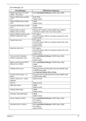
... DIMM System board DIMM System board DIMM System board Run Load Default Settings in BIOS Setup Utility. Run Setup Shadow RAM Failed at offset: nnnn System RAM Failed at offset: nnnn Extended RAM Failed at offset: nnnn System battery is defined with the proper diskette type in BIOS Setup Utility. RTC battery Run...
... DIMM System board DIMM System board DIMM System board Run Load Default Settings in BIOS Setup Utility. Run Setup Shadow RAM Failed at offset: nnnn System RAM Failed at offset: nnnn Extended RAM Failed at offset: nnnn System battery is defined with the proper diskette type in BIOS Setup Utility. RTC battery Run...


