
Acer Altos 1100e User's Guide
Page 9
... 2-12 2.7 Installing and Removing a Heatsink 2-13 2.8 Installing a Pentium III Processor 2-15 2.9 Removing a Pentium III Processor 2-17 2.10 Installing the Termination Board 2-18 2.11 Memory Upgrade 2-19 2.11.1 Memory Configurations 2-19 2.11.2 Installing a DIMM 2-20 2.11.3 Removing a DIMM 2-21 2.11.4 Reconfiguring the System 2-21 2.12 Installing Expansion Cards 2-22 2.12.1 Installing 32 Bit...
... 2-12 2.7 Installing and Removing a Heatsink 2-13 2.8 Installing a Pentium III Processor 2-15 2.9 Removing a Pentium III Processor 2-17 2.10 Installing the Termination Board 2-18 2.11 Memory Upgrade 2-19 2.11.1 Memory Configurations 2-19 2.11.2 Installing a DIMM 2-20 2.11.3 Removing a DIMM 2-21 2.11.4 Reconfiguring the System 2-21 2.12 Installing Expansion Cards 2-22 2.12.1 Installing 32 Bit...
Acer Altos 1100e User's Guide
Page 10
... Secondary Channel Master 3-6 3.2.11 IDE Secondary Channel Slave 3-6 3.2.12 Total Memory 3-6 3.2.13 Serial Port 1 3-7 3.2.14 Serial Port 2 3-7 3.2.15 Parallel Port 3-7 3.2.16 Pointing Device 3-7 3.2.17 Memory Parity Mode 3-7 3.2.18 Onboard USB 3-7 3.3 Product Information 3-8 3.3.1 Product Name 3-8 3.3.2 System S/N 3-8 3.3.3 Main Board ID 3-9 3.3.4 Main Board S/N 3-9 3.3.5 System BIOS Version 3-9 3.3.6 System BIOS ID 3-9 3.3.7 BIOS Release Date 3-9 x Altos 1100E Series User's Guide
... Secondary Channel Master 3-6 3.2.11 IDE Secondary Channel Slave 3-6 3.2.12 Total Memory 3-6 3.2.13 Serial Port 1 3-7 3.2.14 Serial Port 2 3-7 3.2.15 Parallel Port 3-7 3.2.16 Pointing Device 3-7 3.2.17 Memory Parity Mode 3-7 3.2.18 Onboard USB 3-7 3.3 Product Information 3-8 3.3.1 Product Name 3-8 3.3.2 System S/N 3-8 3.3.3 Main Board ID 3-9 3.3.4 Main Board S/N 3-9 3.3.5 System BIOS Version 3-9 3.3.6 System BIOS ID 3-9 3.3.7 BIOS Release Date 3-9 x Altos 1100E Series User's Guide

Acer Altos 1100e User's Guide
Page 14
List of Tables 2-1 System Board Jumper Settings 2-6 2-2 Connector Functions 2-7 2-3 Memory Configurations 2-19 2-4 System Error Messages 2-27 3-1 Parallel Port Operation Mode Settings 3-27 3-2 Drive Control Settings 3-40 4-1 Default Settings for SCSI Controller and all Devices 4-2 xiv Altos 1100E Series User's Guide
List of Tables 2-1 System Board Jumper Settings 2-6 2-2 Connector Functions 2-7 2-3 Memory Configurations 2-19 2-4 System Error Messages 2-27 3-1 Parallel Port Operation Mode Settings 3-27 3-2 Drive Control Settings 3-40 4-1 Default Settings for SCSI Controller and all Devices 4-2 xiv Altos 1100E Series User's Guide
Acer Altos 1100e User's Guide
Page 47
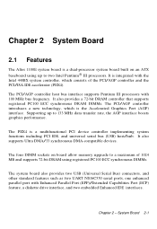
...)/Extended Capabilities Port (ECP) feature, a diskette drive interface, and two embedded Enhanced IDE interfaces. Chapter 2 System Board 2.1 Features The Altos 1100E system board is a dual-processor system board built on board allow memory upgrade to 133 MHz data transfer rate, the AGP interface boosts graphics performance. It is a multifunctional PCI device controller implementing...
...)/Extended Capabilities Port (ECP) feature, a diskette drive interface, and two embedded Enhanced IDE interfaces. Chapter 2 System Board 2.1 Features The Altos 1100E system board is a dual-processor system board built on board allow memory upgrade to 133 MHz data transfer rate, the AGP interface boosts graphics performance. It is a multifunctional PCI device controller implementing...
Acer Altos 1100e User's Guide
Page 49
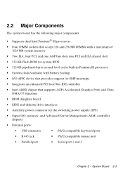
...Supports dual Intel Pentium III processors • Four DIMM sockets that accept 128 and 256 MB DIMMs with a maximum of 1024 MB system memory • Two ISA, four PCI, and one AGP bus slots (one PCI and ISA shared slot) • 512-KB Flash ROM for... • RDM daughter board • EIDE and diskette drive interfaces • Auxiliary power connector for the switching power supply (SPS) • Super I/O, memory, and Advanced Server Management (ASM) controller chipsets • External ports: • USB connector • PS/2-compatible keyboard port • RJ-45 jack ...
...Supports dual Intel Pentium III processors • Four DIMM sockets that accept 128 and 256 MB DIMMs with a maximum of 1024 MB system memory • Two ISA, four PCI, and one AGP bus slots (one PCI and ISA shared slot) • 512-KB Flash ROM for... • RDM daughter board • EIDE and diskette drive interfaces • Auxiliary power connector for the switching power supply (SPS) • Super I/O, memory, and Advanced Server Management (ASM) controller chipsets • External ports: • USB connector • PS/2-compatible keyboard port • RJ-45 jack ...
Acer Altos 1100e User's Guide
Page 61
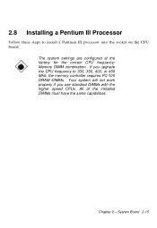
If you use standard DIMMs with the higher speed CPUs. Chapter 2 - The system settings are configured at the factory for the correct CPU frequency/ Memory DIMM combination. System Board 2-15 2.8 Installing a Pentium III Processor Follow these steps to 300, 350, 400, or 450 MHz, the memory controller requires PC-100 DRAM DIMMs. Your system will not work properly if you upgrade the CPU frequency to install a Pentium III processor into the socket on the CPU board. All of the installed DIMMs must have the same capabilities.
If you use standard DIMMs with the higher speed CPUs. Chapter 2 - The system settings are configured at the factory for the correct CPU frequency/ Memory DIMM combination. System Board 2-15 2.8 Installing a Pentium III Processor Follow these steps to 300, 350, 400, or 450 MHz, the memory controller requires PC-100 DRAM DIMMs. Your system will not work properly if you upgrade the CPU frequency to install a Pentium III processor into the socket on the CPU board. All of the installed DIMMs must have the same capabilities.
Acer Altos 1100e User's Guide
Page 65
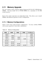
...represents one independent bank. This allows you to install DIMMs with various capacities to form a configuration. 2.11.1 Memory Configurations Table 2-3 lists some system memory configurations. 2.11 Memory Upgrade The four 168-pin sockets onboard support Registered PC100 ECC SDRAM-type DIMMs. You may combine DIMMs with ...different capacities to form other combinations. Table 2-3 Memory Configurations DIMM1 128MB 128MB 128MB 128MB 256 MB 256 MB 256 MB 256 MB DIMM2 128MB 128MB 128MB 256 MB 256 MB...
...represents one independent bank. This allows you to install DIMMs with various capacities to form a configuration. 2.11.1 Memory Configurations Table 2-3 lists some system memory configurations. 2.11 Memory Upgrade The four 168-pin sockets onboard support Registered PC100 ECC SDRAM-type DIMMs. You may combine DIMMs with ...different capacities to form other combinations. Table 2-3 Memory Configurations DIMM1 128MB 128MB 128MB 128MB 256 MB 256 MB 256 MB 256 MB DIMM2 128MB 128MB 128MB 256 MB 256 MB...
Acer Altos 1100e User's Guide
Page 67
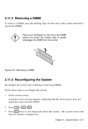
... remove a DIMM, press the holding clips to gently disengage the DIMM from the socket. A memory error message appears, indicating that the total memory does not match the value stored in CMOS. 2. Press + +. 3. The system boots with the new memory configuration. Place your forefingers on the top of the socket outward to release the...
... remove a DIMM, press the holding clips to gently disengage the DIMM from the socket. A memory error message appears, indicating that the total memory does not match the value stored in CMOS. 2. Press + +. 3. The system boots with the new memory configuration. Place your forefingers on the top of the socket outward to release the...
Acer Altos 1100e User's Guide
Page 74
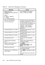
... disable the port. Press error. Check the memory size based on the system board. Press or + + Setup. Check the internal cable connections. Run Setup (See Section 3.1) and disable the port. to reboot the system. 2-28 Altos 1100E Series User's Guide If you are sure that...Section 3.1) and set the time and date. Table 2-4 System Error Messages (continued) Message Memory Error at: MMMM:SSSS:OOO (W:XXXX, R:YYYY) where: M: MB, S: Segment, O: Offset, X/Y: write/read pattern Memory Size Mismatch CPU Clock Mismatch Onboard Serial Port 1 Conflict Onboard Serial Port 2 Conflict Onboard ...
... disable the port. Press error. Check the memory size based on the system board. Press or + + Setup. Check the internal cable connections. Run Setup (See Section 3.1) and disable the port. to reboot the system. 2-28 Altos 1100E Series User's Guide If you are sure that...Section 3.1) and set the time and date. Table 2-4 System Error Messages (continued) Message Memory Error at: MMMM:SSSS:OOO (W:XXXX, R:YYYY) where: M: MB, S: Segment, O: Offset, X/Y: write/read pattern Memory Size Mismatch CPU Clock Mismatch Onboard Serial Port 1 Conflict Onboard Serial Port 2 Conflict Onboard ...
Acer Altos 1100e User's Guide
Page 77
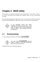
... for assistance. 3.1 Entering Setup To enter Setup, press the key combination ++. The Setup program loads configuration values into the battery-backed nonvolatile memory called CMOS RAM. If you get a Run Setup message. Chapter 3 BIOS Utility Most systems are already configured by the manufacturer or the dealer. ...This memory area is booting. BIOS Utility 3-1 In this case, the system cannot retain configuration values in CMOS. There is no need to run...
... for assistance. 3.1 Entering Setup To enter Setup, press the key combination ++. The Setup program loads configuration values into the battery-backed nonvolatile memory called CMOS RAM. If you get a Run Setup message. Chapter 3 BIOS Utility Most systems are already configured by the manufacturer or the dealer. ...This memory area is booting. BIOS Utility 3-1 In this case, the system cannot retain configuration values in CMOS. There is no need to run...
Acer Altos 1100e User's Guide
Page 79
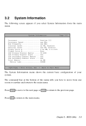
... Drive A x.xx MB, x.x-inch Floppy Drive B None IDE Primary Channel Master ..... CD-ROM IDE Primary Channel Slave ...... xxx IDE Secondary Channel Master ... xxx Total Memory xx MB Memory type SDRAM PgDn/PgUp = Move Screen, Esc = Back to Main Menu The System Information menu shows the current basic configuration of the menu tells...
... Drive A x.xx MB, x.x-inch Floppy Drive B None IDE Primary Channel Master ..... CD-ROM IDE Primary Channel Slave ...... xxx IDE Secondary Channel Master ... xxx Total Memory xx MB Memory type SDRAM PgDn/PgUp = Move Screen, Esc = Back to Main Menu The System Information menu shows the current basic configuration of the menu tells...
Acer Altos 1100e User's Guide
Page 80
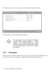
The following sections explain the parameters. System Information Serial Port 1 3F8h, IRQ 4 Serial Port 2 2F8h, IRQ 3 Parallel Port 378h, IRQ 7 Pointing Device Installed Memory Parity Mode ECC Onboard USB Disabled Page 2/2 PgDn/PgUp = Move Screen, Esc = Back to Main Menu The following screen shows page 2 of processor currently installed ... the type of the System Information menu. These settings are non-configurable from the BIOS Utility main menu to support the Intel Pentium III processor. 3-4 Altos 1100E Series User's Guide
The following sections explain the parameters. System Information Serial Port 1 3F8h, IRQ 4 Serial Port 2 2F8h, IRQ 3 Parallel Port 378h, IRQ 7 Pointing Device Installed Memory Parity Mode ECC Onboard USB Disabled Page 2/2 PgDn/PgUp = Move Screen, Esc = Back to Main Menu The following screen shows page 2 of processor currently installed ... the type of the System Information menu. These settings are non-configurable from the BIOS Utility main menu to support the Intel Pentium III processor. 3-4 Altos 1100E Series User's Guide

Acer Altos 1100e User's Guide
Page 81
... specifies the type of the CPU currently installed in your system. Chapter 3 - The bus frequency should always be set to configure the system memory, see section 3.4.1. 3.2.7 Floppy Drive B This parameter specifies the system's current floppy drive B settings. For information on how to 100 MHz.... 3.2.4 Internal Cache This parameter specifies the first-level or the internal memory size (i.e., the memory integrated into the CPU), and whether it is enabled or disabled. For information on how to two Intel Pentium III processors. ...
... specifies the type of the CPU currently installed in your system. Chapter 3 - The bus frequency should always be set to configure the system memory, see section 3.4.1. 3.2.7 Floppy Drive B This parameter specifies the system's current floppy drive B settings. For information on how to 100 MHz.... 3.2.4 Internal Cache This parameter specifies the first-level or the internal memory size (i.e., the memory integrated into the CPU), and whether it is enabled or disabled. For information on how to two Intel Pentium III processors. ...
Acer Altos 1100e User's Guide
Page 82
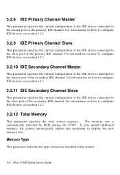
...3.2.8 IDE Primary Channel Master This parameter specifies the current configuration of the IDE device connected to the master port of memory installed in the system. 3-6 Altos 1100E Series User's Guide For information on how to configure IDE devices, see section 3.4.2. 3.2.10 IDE Secondary Channel Master ...IDE device connected to configure IDE devices, see section 3.4.2. 3.2.12 Total Memory This parameter specifies the total system memory. For information on how to the slave port of the secondary IDE channel. Memory Type This parameter indicates the type of the primary IDE channel. For...
...3.2.8 IDE Primary Channel Master This parameter specifies the current configuration of the IDE device connected to the master port of memory installed in the system. 3-6 Altos 1100E Series User's Guide For information on how to configure IDE devices, see section 3.4.2. 3.2.10 IDE Secondary Channel Master ...IDE device connected to configure IDE devices, see section 3.4.2. 3.2.12 Total Memory This parameter specifies the total system memory. For information on how to the slave port of the secondary IDE channel. Memory Type This parameter indicates the type of the primary IDE channel. For...

Acer Altos 1100e User's Guide
Page 83
.... The default setting is ECC. 3.2.18 Onboard USB This parameter specifies whether the onboard USB controller is set to None. 3.2.17 Memory Parity Mode This parameter indicates the setting of the memory parity mode. BIOS Utility 3-7 For information on how to the system. If there is a mouse connected to enable or disable...
.... The default setting is ECC. 3.2.18 Onboard USB This parameter specifies whether the onboard USB controller is set to None. 3.2.17 Memory Parity Mode This parameter indicates the setting of the memory parity mode. BIOS Utility 3-7 For information on how to the system. If there is a mouse connected to enable or disable...
Acer Altos 1100e User's Guide
Page 91
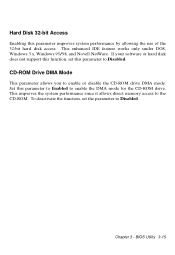
This enhanced IDE feature works only under DOS, Windows 3.x, Windows 95/98, and Novell NetWare. This improves the system performance since it allows direct memory access to enable or disable the CD-ROM drive DMA mode. BIOS Utility 3-15 Set this parameter improves system performance by allowing the use of ...
This enhanced IDE feature works only under DOS, Windows 3.x, Windows 95/98, and Novell NetWare. This improves the system performance since it allows direct memory access to enable or disable the CD-ROM drive DMA mode. BIOS Utility 3-15 Set this parameter improves system performance by allowing the use of ...
Acer Altos 1100e User's Guide
Page 94
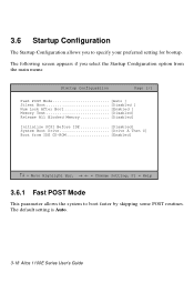
... Page 1/1 Fast POST Mode Auto ] Silent Boot Disabled ] Num Lock After Boot Enabled ] Memory Test Disabled] Release All Blocked Memory Disabled] Initialize SCSI Before IDE Disabled] System Boot Drive Drive A Then C] Boot from IDE ...CD-ROM Enabled] ↑↓ = Move Highlight Bar, → ← = Change Setting, F1 = Help 3.6.1 Fast POST Mode This parameter allows the system to specify your preferred setting for bootup. The default setting is Auto. 3-18 Altos 1100E...
... Page 1/1 Fast POST Mode Auto ] Silent Boot Disabled ] Num Lock After Boot Enabled ] Memory Test Disabled] Release All Blocked Memory Disabled] Initialize SCSI Before IDE Disabled] System Boot Drive Drive A Then C] Boot from IDE ...CD-ROM Enabled] ↑↓ = Move Highlight Bar, → ← = Change Setting, F1 = Help 3.6.1 Fast POST Mode This parameter allows the system to specify your preferred setting for bootup. The default setting is Auto. 3-18 Altos 1100E...
Acer Altos 1100e User's Guide
Page 95
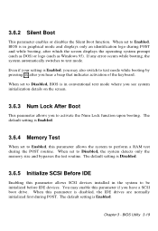
... the system to be initialized before IDE devices. 3.6.2 Silent Boot This parameter enables or disables the Silent Boot function. Even if your setting is Enabled. 3.6.4 Memory Test When set to text mode while booting by pressing after which the screen displays the operating system prompt (such as DOS) or logo (such... during POST and while booting, after you have a SCSI boot drive. BIOS Utility 3-19 You may also switch to Disabled, the system detects only the memory size and bypasses the test routine. The default setting is Enabled.
... the system to be initialized before IDE devices. 3.6.2 Silent Boot This parameter enables or disables the Silent Boot function. Even if your setting is Enabled. 3.6.4 Memory Test When set to text mode while booting by pressing after which the screen displays the operating system prompt (such as DOS) or logo (such... during POST and while booting, after you have a SCSI boot drive. BIOS Utility 3-19 You may also switch to Disabled, the system detects only the memory size and bypasses the test routine. The default setting is Enabled.
Acer Altos 1100e User's Guide
Page 97
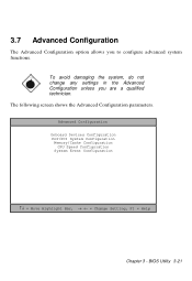
The following screen shows the Advanced Configuration parameters. 3.7 Advanced Configuration The Advanced Configuration option allows you are a qualified technician. To avoid damaging the system, do not change any settings in the Advanced Configuration unless you to configure advanced system functions. BIOS Utility 3-21 Advanced Configuration Onboard Devices Configuration PnP/PCI System Configuration Memory/Cache Configuration CPU Speed Configuration System Event Configuration ↑↓ = Move Highlight Bar, → ← = Change Setting, F1 = Help Chapter 3 -
The following screen shows the Advanced Configuration parameters. 3.7 Advanced Configuration The Advanced Configuration option allows you are a qualified technician. To avoid damaging the system, do not change any settings in the Advanced Configuration unless you to configure advanced system functions. BIOS Utility 3-21 Advanced Configuration Onboard Devices Configuration PnP/PCI System Configuration Memory/Cache Configuration CPU Speed Configuration System Event Configuration ↑↓ = Move Highlight Bar, → ← = Change Setting, F1 = Help Chapter 3 -

Acer Altos 1100e User's Guide
Page 109
... Configuration Page 1/1 Internal Cache (CPU Cache Enabled ] Cache Scheme Write Back] System BIOS Cacheable Enabled ] Video BIOS Cacheable Enabled ] Memory at 15MB-16MB Reserved for .... [ System ] Memory ECC Mode ECC ] Single Processor MP Table Enabled] ↑↓ = Move Highlight Bar, → ← = Change Setting, F1 = Help Internal Cache (CPU Cache) This parameter...
... Configuration Page 1/1 Internal Cache (CPU Cache Enabled ] Cache Scheme Write Back] System BIOS Cacheable Enabled ] Video BIOS Cacheable Enabled ] Memory at 15MB-16MB Reserved for .... [ System ] Memory ECC Mode ECC ] Single Processor MP Table Enabled] ↑↓ = Move Highlight Bar, → ← = Change Setting, F1 = Help Internal Cache (CPU Cache) This parameter...
