

aa500ug.pdf
Page 7
.... Chapter 1 System Board Describes the system board and all its major components. Chapter 2 BIOS Utility Gives information about the system BIOS and tells how to install basic system components into the housing. Chapter 3 SCSISelect Configuration Utility This chapter describes the SCSISelect Configuration Utility, which allows you ...
.... Chapter 1 System Board Describes the system board and all its major components. Chapter 2 BIOS Utility Gives information about the system BIOS and tells how to install basic system components into the housing. Chapter 3 SCSISelect Configuration Utility This chapter describes the SCSISelect Configuration Utility, which allows you ...

aa500ug.pdf
Page 10
Chapter 2 BIOS Utility 2.1 Entering Setup 2-1 2.2 System Information 2-4 2.2.1 Processor 2-5 2.2.2 Processor Speed 2-5 2.2.3 Internal Cache Size 2-5 2.2.4 External Cache 2-5 2.2.5 Floppy Drive A 2-6 2.2.6... 2-7 2.2.15 PS/2 Mouse 2-7 2.3 Product Information 2-8 2.3.1 Product Name 2-8 2.3.2 System S/N 2-8 2.3.3 Main Board ID 2-8 2.3.4 Main Board S/N 2-9 2.3.5 System BIOS Version 2-9 2.3.6 DMI BIOS Version 2-9 2.4 Disk Drives ...2-10 2.4.1 Floppy Drives 2-10 2.4.2 LS-120 Drive Compatible As 2-11 2.4.3 IDE Drives 2-12 2.5 Onboard Peripherals 2-16 x Altos 500 Series User's Guide
Chapter 2 BIOS Utility 2.1 Entering Setup 2-1 2.2 System Information 2-4 2.2.1 Processor 2-5 2.2.2 Processor Speed 2-5 2.2.3 Internal Cache Size 2-5 2.2.4 External Cache 2-5 2.2.5 Floppy Drive A 2-6 2.2.6... 2-7 2.2.15 PS/2 Mouse 2-7 2.3 Product Information 2-8 2.3.1 Product Name 2-8 2.3.2 System S/N 2-8 2.3.3 Main Board ID 2-8 2.3.4 Main Board S/N 2-9 2.3.5 System BIOS Version 2-9 2.3.6 DMI BIOS Version 2-9 2.4 Disk Drives ...2-10 2.4.1 Floppy Drives 2-10 2.4.2 LS-120 Drive Compatible As 2-11 2.4.3 IDE Drives 2-12 2.5 Onboard Peripherals 2-16 x Altos 500 Series User's Guide
aa500ug.pdf
Page 12
... Disk Utilities 3-19 3.3 Configuring Multiple SCSI Controllers 3-21 3.4 SCSI Troubleshooting Checklist 3-22 3.5 BIOS Startup Messages 3-23 Chapter 4 System Housing 4.1 Features...4-2 4.1.1 Front Panel 4-2 4.1.2 Rear Panel 4-3 4.2 Internal Structure 4-4 4.3 Opening the Housing Panels 4-5 4.3.1 Front Panel 4-5 4.3.2 Left Panel 4-6 4.4 Installing Drives 4-7 4.4.1 3.5-inch Drive 4-7 4.4.2 5.25-inch Drives 4-9 4.5 Installing an Expansion Board 4-11 INDEX xii Altos 500 Series User's Guide
... Disk Utilities 3-19 3.3 Configuring Multiple SCSI Controllers 3-21 3.4 SCSI Troubleshooting Checklist 3-22 3.5 BIOS Startup Messages 3-23 Chapter 4 System Housing 4.1 Features...4-2 4.1.1 Front Panel 4-2 4.1.2 Rear Panel 4-3 4.2 Internal Structure 4-4 4.3 Opening the Housing Panels 4-5 4.3.1 Front Panel 4-5 4.3.2 Left Panel 4-6 4.4 Installing Drives 4-7 4.4.1 3.5-inch Drive 4-7 4.4.2 5.25-inch Drives 4-9 4.5 Installing an Expansion Board 4-11 INDEX xii Altos 500 Series User's Guide
aa500ug.pdf
Page 16
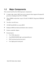
...; 256-KB Flash ROM for system BIOS • Enhanced IDE hard disk and diskette drive interface • System controller chipset • External ports: • Two USB connectors • One SPP/ECP/EPP high speed parallel port • PS/2 keyboard and mouse ports • Two high speed serial ports Altos 500 Series User's Guide
...; 256-KB Flash ROM for system BIOS • Enhanced IDE hard disk and diskette drive interface • System controller chipset • External ports: • Two USB connectors • One SPP/ECP/EPP high speed parallel port • PS/2 keyboard and mouse ports • Two high speed serial ports Altos 500 Series User's Guide
aa500ug.pdf
Page 19
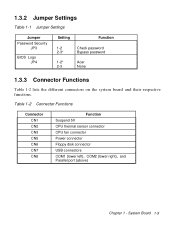
1.3.2 Jumper Settings Table 1-1 Jumper Settings Jumper Password Security JP3 BIOS Logo JP4 Setting Function 1-2 Check password 2-3* Bypass password 1-2* Acer 2-3 None 1.3.3 Connector Functions Table 1-2 lists the different connectors on the system board and their respective functions. System Board 1-5 Table 1-2 Connector Functions Connector CN1 CN2 CN3 CN5 CN6 CN7 CN8 Function Suspend 5V CPU thermal sensor connector CPU fan connector Power connector Floppy disk connector USB connectors COM1 (lower left), COM2 (lower right), and Parallel port (above) Chapter 1 -
1.3.2 Jumper Settings Table 1-1 Jumper Settings Jumper Password Security JP3 BIOS Logo JP4 Setting Function 1-2 Check password 2-3* Bypass password 1-2* Acer 2-3 None 1.3.3 Connector Functions Table 1-2 lists the different connectors on the system board and their respective functions. System Board 1-5 Table 1-2 Connector Functions Connector CN1 CN2 CN3 CN5 CN6 CN7 CN8 Function Suspend 5V CPU thermal sensor connector CPU fan connector Power connector Floppy disk connector USB connectors COM1 (lower left), COM2 (lower right), and Parallel port (above) Chapter 1 -
aa500ug.pdf
Page 36
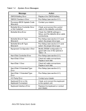
... drive type. Replace the keyboard or contact your dealer. Table 1-4 System Error Messages Message CMOS Battery Error CMOS Checksum Error Processor BIOS Update Code Mismatch Diskette Drive Controller Error or Not Installed Diskette Drive Error Diskette Drive A Type Mismatch Diskette Drive B Type Mismatch ...Replace the CMOS battery. Run Setup (see section 2.1). Replace hard disk. Check the CMOS settings in Table 1-4. Contact your dealer. Altos 500 Series User's Guide Replace hard disk. Modify DRAM configuration to agree with one of the options in Setup and the diskette drive cable...
... drive type. Replace the keyboard or contact your dealer. Table 1-4 System Error Messages Message CMOS Battery Error CMOS Checksum Error Processor BIOS Update Code Mismatch Diskette Drive Controller Error or Not Installed Diskette Drive Error Diskette Drive A Type Mismatch Diskette Drive B Type Mismatch ...Replace the CMOS battery. Run Setup (see section 2.1). Replace hard disk. Check the CMOS settings in Table 1-4. Contact your dealer. Altos 500 Series User's Guide Replace hard disk. Modify DRAM configuration to agree with one of the options in Setup and the diskette drive cable...

aa500ug.pdf
Page 39
... RAM. There is no need to view and change your system's configuration settings. This key combination does not work during any other time. Chapter 2 BIOS Utility The BIOS Utility allows you to run Setup, make sure that you have saved all open files. In this case, the system cannot retain configuration values...
... RAM. There is no need to view and change your system's configuration settings. This key combination does not work during any other time. Chapter 2 BIOS Utility The BIOS Utility allows you to run Setup, make sure that you have saved all open files. In this case, the system cannot retain configuration values...

aa500ug.pdf
Page 40
The Setup Utility Main Menu appears: Setup Utility • System Information • Product Information • Disk Drives • Onboard Peripherals • Power Management • Boot Options • Date and Time • System Security • Load Default Settings • Abort Settings Change The system supports two BIOS Utility levels: Basic and Advanced. The above screen is the BIOS Utility Basic Level screen. This allows you to view and change only the basic configuration of your system. Altos 500 Series User's Guide
The Setup Utility Main Menu appears: Setup Utility • System Information • Product Information • Disk Drives • Onboard Peripherals • Power Management • Boot Options • Date and Time • System Security • Load Default Settings • Abort Settings Change The system supports two BIOS Utility levels: Basic and Advanced. The above screen is the BIOS Utility Basic Level screen. This allows you to view and change only the basic configuration of your system. Altos 500 Series User's Guide

aa500ug.pdf
Page 41
... parameters on the screens have fixed settings and are in the Advanced Level. Detailed system configurations are contained in your system. The screen shows the BIOS Utility Advanced Level main menu. BIOS Utility 2-3 These values may want to check the detailed configuration of your system.
... parameters on the screens have fixed settings and are in the Advanced Level. Detailed system configurations are contained in your system. The screen shows the BIOS Utility Advanced Level main menu. BIOS Utility 2-3 These values may want to check the detailed configuration of your system.

aa500ug.pdf
Page 43
... Processor parameter specifies the type of processor currently installed in your system. At the time of printing, the system supports Pentium III processors running at 500 and 550 MHz. BIOS Utility 2-5
... Processor parameter specifies the type of processor currently installed in your system. At the time of printing, the system supports Pentium III processors running at 500 and 550 MHz. BIOS Utility 2-5

aa500ug.pdf
Page 45
... Port 1 This parameter shows the serial port 1 address and IRQ setting. The default setting is Installed. The default setting is automatically detected by BIOS during the POST. If you install additional memory, the system automatically adjusts this is a pointing device connected to display the new memory size. 1st... address and IRQ setting. If there is no DRAM installed. The default setting is 378h, IRQ 7. 2.2.15 PS/2 Mouse The BIOS utility automatically detects if there is set to None. The None setting indicates that there is , this parameter displays the Installed setting.
... Port 1 This parameter shows the serial port 1 address and IRQ setting. The default setting is Installed. The default setting is automatically detected by BIOS during the POST. If you install additional memory, the system automatically adjusts this is a pointing device connected to display the new memory size. 1st... address and IRQ setting. If there is no DRAM installed. The default setting is 378h, IRQ 7. 2.2.15 PS/2 Mouse The BIOS utility automatically detects if there is set to None. The None setting indicates that there is , this parameter displays the Installed setting.
aa500ug.pdf
Page 46
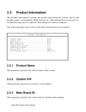
... troubleshooting (may be required when asking for technical support). Altos 500 Series User's Guide The following figure shows how the Product Information screen appears: Product Information Product Name M11E System S/N N/A Main Board ID M11E Main Board S/N N/A System BIOS Version v3.1 SIMM BIOS Version 2.1 System BIOS ID XXXX BIOS Release Date MM-DD-YY 2.3.1 Product Name This... specifies the system board's identification number. 2.3 Product Information The Product Information contains the general data about the system, such as the product name, serial number, BIOS version, etc.
... troubleshooting (may be required when asking for technical support). Altos 500 Series User's Guide The following figure shows how the Product Information screen appears: Product Information Product Name M11E System S/N N/A Main Board ID M11E Main Board S/N N/A System BIOS Version v3.1 SIMM BIOS Version 2.1 System BIOS ID XXXX BIOS Release Date MM-DD-YY 2.3.1 Product Name This... specifies the system board's identification number. 2.3 Product Information The Product Information contains the general data about the system, such as the product name, serial number, BIOS version, etc.
aa500ug.pdf
Page 47
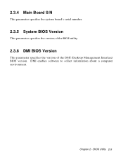
DMI enables software to collect information about a computer environment. 2.3.4 Main Board S/N This parameter specifies the system board's serial number. 2.3.5 System BIOS Version This parameter specifies the version of the BIOS utility. 2.3.6 DMI BIOS Version This parameter specifies the version of the DMI (Desktop Management Interface) BIOS version. Chapter 2 - BIOS Utility 2-9
DMI enables software to collect information about a computer environment. 2.3.4 Main Board S/N This parameter specifies the system board's serial number. 2.3.5 System BIOS Version This parameter specifies the version of the BIOS utility. 2.3.6 DMI BIOS Version This parameter specifies the version of the DMI (Desktop Management Interface) BIOS version. Chapter 2 - BIOS Utility 2-9

aa500ug.pdf
Page 49
...LS-120 drive as drive B. In this server. Although LS-120 options are provided in the system BIOS, LS-120 drives are : • Normal In this setting, BIOS does not support the LS-120 drive. BIOS Utility 2-11 If a standard diskette drive B exists, it as drive B. Possible settings are neither qualified... nor supported in this setting, format the LS-120 drive as any other hard disk and assign it becomes inaccessible. • Hard Disk BIOS recognizes the LS-120 drive as a hard disk. The drive needs the LS-120 device driver to specify the function of the device. If ...
...LS-120 drive as drive B. In this server. Although LS-120 options are provided in the system BIOS, LS-120 drives are : • Normal In this setting, BIOS does not support the LS-120 drive. BIOS Utility 2-11 If a standard diskette drive B exists, it as drive B. Possible settings are neither qualified... nor supported in this setting, format the LS-120 drive as any other hard disk and assign it becomes inaccessible. • Hard Disk BIOS recognizes the LS-120 drive as a hard disk. The drive needs the LS-120 device driver to specify the function of the device. If ...

aa500ug.pdf
Page 50
... this server. IDE Secondary Channel Master This parameter lets you configure the hard disk drive connected to the master port of IDE channel 2. Altos 500 Series User's Guide IDE Primary Channel Slave This parameter lets you configure the hard disk drive connected to the slave port of IDE channel ...1. The IDE options are neither qualified nor supported in the system BIOS, IDE hard disk drives are : IDE Primary Channel Master This parameter lets you configure the hard disk drive connected to the master port...
... this server. IDE Secondary Channel Master This parameter lets you configure the hard disk drive connected to the master port of IDE channel 2. Altos 500 Series User's Guide IDE Primary Channel Slave This parameter lets you configure the hard disk drive connected to the slave port of IDE channel ...1. The IDE options are neither qualified nor supported in the system BIOS, IDE hard disk drives are : IDE Primary Channel Master This parameter lets you configure the hard disk drive connected to the master port...

aa500ug.pdf
Page 51
If you can enter the setting manually. If you know your hard disk type, you want BIOS to section 2.1 for more information. BIOS Utility 2-13 Setting this parameter also sets the Cylinder, Head, Sector, and Size parameters. Cylinder This parameter specifies the number of cylinders of hard disk ...
If you can enter the setting manually. If you know your hard disk type, you want BIOS to section 2.1 for more information. BIOS Utility 2-13 Setting this parameter also sets the Cylinder, Head, Sector, and Size parameters. Cylinder This parameter specifies the number of cylinders of hard disk ...

aa500ug.pdf
Page 52
...you set depending on your Type parameter setting. Size This parameter specifies the size of 256 bytes per cycle. This is Auto. Altos 500 Series User's Guide The default setting is made possible through the Logical Block Address (LBA) mode translation. This is automatically set to...function. Hard Disk Block Mode This function enhances disk performance depending on your Type parameter setting. If you to Auto, the BIOS utility automatically detects if the installed hard disk drive supports the Block Mode function. Other operating systems require this parameter to Disabled...
...you set depending on your Type parameter setting. Size This parameter specifies the size of 256 bytes per cycle. This is Auto. Altos 500 Series User's Guide The default setting is made possible through the Logical Block Address (LBA) mode translation. This is automatically set to...function. Hard Disk Block Mode This function enhances disk performance depending on your Type parameter setting. If you to Auto, the BIOS utility automatically detects if the installed hard disk drive supports the Block Mode function. Other operating systems require this parameter to Disabled...

aa500ug.pdf
Page 53
...performance by allowing the use of 32bit hard disk access. The default setting is Hard Disk 32-Bit Access Enabling this parameter to Auto, BIOS automatically sets the appropriate DMA mode for faster data recovery and read/write timing that reduces hard disk activity time. This parameter appears only when... performance since it allows for your software or hard disk does not support this function, set this parameter to Enabled to Disabled. Chapter 2 - BIOS Utility 2-15 To disregard the feature, change the setting to enable the DMA mode for the CD-ROM drive. CD-ROM Drive DMA Mode Set...
...performance by allowing the use of 32bit hard disk access. The default setting is Hard Disk 32-Bit Access Enabling this parameter to Auto, BIOS automatically sets the appropriate DMA mode for faster data recovery and read/write timing that reduces hard disk activity time. This parameter appears only when... performance since it allows for your software or hard disk does not support this function, set this parameter to Enabled to Disabled. Chapter 2 - BIOS Utility 2-15 To disregard the feature, change the setting to enable the DMA mode for the CD-ROM drive. CD-ROM Drive DMA Mode Set...

aa500ug.pdf
Page 55
... a parallel port whose address conflicts with the onboard parallel port, a warning appears on card and change the address to enable or disable the parallel port. BIOS Utility 2-17 Base Address This function lets you set a logical base address for serial ports 1 are IRQ 4 and 11. Chapter 2 - The options for the parallel...
... a parallel port whose address conflicts with the onboard parallel port, a warning appears on card and change the address to enable or disable the parallel port. BIOS Utility 2-17 Base Address This function lets you set a logical base address for serial ports 1 are IRQ 4 and 11. Chapter 2 - The options for the parallel...
aa500ug.pdf
Page 57
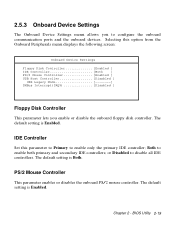
The default setting is Enabled. or Disabled to enable both primary and secondary IDE controllers; The default setting is Enabled. BIOS Utility 2-19 Both to disable all IDE controllers. Selecting this parameter to Primary to configure the onboard communication ports and the onboard devices. The default ...
The default setting is Enabled. or Disabled to enable both primary and secondary IDE controllers; The default setting is Enabled. BIOS Utility 2-19 Both to disable all IDE controllers. Selecting this parameter to Primary to configure the onboard communication ports and the onboard devices. The default ...


