
Acer Altos G610 User's Guide
Page 7
Contents Notices iii FCC notice iii Important safety instructions iv Laser compliance statement vi 1 System overview 1 Overview 3 Processors 3 Memory 4 System chipsets 4 Expansion slots 5 Hardware management support 6 Features summary 7 2 System tour 9 External and internal structure 11 Front panel 11 Rear panel 12 Internal components 13 ...
Contents Notices iii FCC notice iii Important safety instructions iv Laser compliance statement vi 1 System overview 1 Overview 3 Processors 3 Memory 4 System chipsets 4 Expansion slots 5 Hardware management support 6 Features summary 7 2 System tour 9 External and internal structure 11 Front panel 11 Rear panel 12 Internal components 13 ...
Acer Altos G610 User's Guide
Page 8
...-swap cage components 48 Replacing a 5.25-inch storage device 52 Removing and installing the CPU 55 Removing a CPU 55 Installing a CPU 55 Removing and installing memory modules 58 Removing a DIMM 58 Installing a DIMM 59 Installing expansion cards 61 Hot-swappable redundant power supply module 63 Removing a 337-watt hot-swappable redundant...
...-swap cage components 48 Replacing a 5.25-inch storage device 52 Removing and installing the CPU 55 Removing a CPU 55 Installing a CPU 55 Removing and installing memory modules 58 Removing a DIMM 58 Installing a DIMM 59 Installing expansion cards 61 Hot-swappable redundant power supply module 63 Removing a 337-watt hot-swappable redundant...
Acer Altos G610 User's Guide
Page 9
Contents IPMI Configuration 94 RDM Configuration 96 Advanced Options 100 Memory/Cache Options 101 PnP/PCI Options 102 Load Default Settings 105 Abort Settings Change 106 Exit Setup 107 Appendix A: ASM Pro quick installation guide 109 ...
Contents IPMI Configuration 94 RDM Configuration 96 Advanced Options 100 Memory/Cache Options 101 PnP/PCI Options 102 Load Default Settings 105 Abort Settings Change 106 Exit Setup 107 Appendix A: ASM Pro quick installation guide 109 ...
Acer Altos G610 User's Guide
Page 13
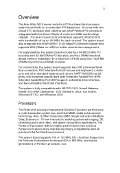
.... For connectivity, the system board supports two USB (Universal Serial Bus) connectors, PS/2 interface for each channel. 3 Overview The Acer Altos G610 server model is fully compatible with all previous Intel Architecture processors. Also, it offers Streaming SIMD (Single Instruction Multiple Data) Extensions -... south bridge chipsets. The system board also integrates the Intel® 82559 10/100 Mbps PCI Ethernet chipset that allows memory installation to a maximum of Pentium processors, too. The dual channel SCSI architecture supports Ultra160 SCSI with bandwidth of up to...
.... For connectivity, the system board supports two USB (Universal Serial Bus) connectors, PS/2 interface for each channel. 3 Overview The Acer Altos G610 server model is fully compatible with all previous Intel Architecture processors. Also, it offers Streaming SIMD (Single Instruction Multiple Data) Extensions -... south bridge chipsets. The system board also integrates the Intel® 82559 10/100 Mbps PCI Ethernet chipset that allows memory installation to a maximum of Pentium processors, too. The dual channel SCSI architecture supports Ultra160 SCSI with bandwidth of up to...
Acer Altos G610 User's Guide
Page 14
...the Ultra-2 SCSI data transfer rate of up to 15 devices on 33 MHz, 32-bit PCI buses. 4 1 System overview Memory The four DIMM sockets on board allow memory upgrade to -point configuration), making it delivers a total of 320 MByte/sec bandwidth. System chipsets Server Works LE north and south... bridge The Server Works CNB30LE (champ north bridge) chipset incorporated as well. Note: The SDRAM should work under 3.3 volts only; 5-volt memory devices are not supported. It supports up to provide the ASM and RDM functions and the industry standard IPMI protocol as the north bridge is...
...the Ultra-2 SCSI data transfer rate of up to 15 devices on 33 MHz, 32-bit PCI buses. 4 1 System overview Memory The four DIMM sockets on board allow memory upgrade to -point configuration), making it delivers a total of 320 MByte/sec bandwidth. System chipsets Server Works LE north and south... bridge The Server Works CNB30LE (champ north bridge) chipset incorporated as well. Note: The SDRAM should work under 3.3 volts only; 5-volt memory devices are not supported. It supports up to provide the ASM and RDM functions and the industry standard IPMI protocol as the north bridge is...
Acer Altos G610 User's Guide
Page 15
... Magic Packet • wake on interesting packet • advanced System Management Bus (SMB) based manageability • Wired for network solution is the integration of video memory and supports up to 1280x1024, it provides an enhanced visual experience on your system. With remarkable color depth and high resolutions of up to 4) •...
... Magic Packet • wake on interesting packet • advanced System Management Bus (SMB) based manageability • Wired for network solution is the integration of video memory and supports up to 1280x1024, it provides an enhanced visual experience on your system. With remarkable color depth and high resolutions of up to 4) •...
Acer Altos G610 User's Guide
Page 17
... sockets that supports a Pentium® III processor running at 600/133 to 1280x1024 resolution with 4-MB onboard VGA SDRAM • System clock/calendar with a maximum memory upgrade of Pentium CPUs • Server Works LE chipset which includes the north and south bridge • SCSI controller chipset Adaptec® AIC-7899 supports...
... sockets that supports a Pentium® III processor running at 600/133 to 1280x1024 resolution with 4-MB onboard VGA SDRAM • System clock/calendar with a maximum memory upgrade of Pentium CPUs • Server Works LE chipset which includes the north and south bridge • SCSI controller chipset Adaptec® AIC-7899 supports...
Acer Altos G610 User's Guide
Page 68
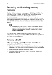
...to form different configurations. WARNING! For a list of qualified DIMM vendors, please contact your system to malfunction. 58 3 Upgrading your system Removing and installing memory modules The four 168-pin sockets on board support SDRAM-type DIMMs. You may install 64-MB, 128-MB, 256-MB, 512-MB, or 1024...MHz SDRAM together. Each of the DIMM sockets is independent from that socket. 1 Open the front panel and remove the side panel of 4-GB system memory. See page 38 for a maximum of the housing. However, they cannot be used at the same time in a socket, remove first any previously ...
...to form different configurations. WARNING! For a list of qualified DIMM vendors, please contact your system to malfunction. 58 3 Upgrading your system Removing and installing memory modules The four 168-pin sockets on board support SDRAM-type DIMMs. You may install 64-MB, 128-MB, 256-MB, 512-MB, or 1024...MHz SDRAM together. Each of the DIMM sockets is independent from that socket. 1 Open the front panel and remove the side panel of 4-GB system memory. See page 38 for a maximum of the housing. However, they cannot be used at the same time in a socket, remove first any previously ...

Acer Altos G610 User's Guide
Page 70
Reverse the orientation of it. If you insert a DIMM but it again. 60 3 Upgrading your system memory The system automatically detects the amount of memory installed. Reconfiguring your system Note: The DIMM socket is slotted to view the new value for total system memory and make a note of the DIMM and insert it does not fit easily into the socket, you may have inserted incorrectly. Run Setup to ensure proper installation.
Reverse the orientation of it. If you insert a DIMM but it again. 60 3 Upgrading your system memory The system automatically detects the amount of memory installed. Reconfiguring your system Note: The DIMM socket is slotted to view the new value for total system memory and make a note of the DIMM and insert it does not fit easily into the socket, you may have inserted incorrectly. Run Setup to ensure proper installation.
Acer Altos G610 User's Guide
Page 79
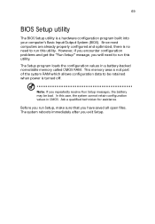
The Setup program loads the configuration values in CMOS. This memory area is not part of the system RAM which allows configuration data to run this utility. Ask a qualified technician for assistance. However, if you encounter ... System (BIOS). Note: If you will need to be bad. Before you run this case, the system cannot retain configuration values in a battery-backed nonvolatile memory called CMOS RAM. The system reboots immediately after you have saved all open files. In this utility. Since most computers are already properly configured and...
The Setup program loads the configuration values in CMOS. This memory area is not part of the system RAM which allows configuration data to run this utility. Ask a qualified technician for assistance. However, if you encounter ... System (BIOS). Note: If you will need to be bad. Before you run this case, the system cannot retain configuration values in a battery-backed nonvolatile memory called CMOS RAM. The system reboots immediately after you have saved all open files. In this utility. Since most computers are already properly configured and...
Acer Altos G610 User's Guide
Page 82
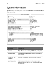
72 4 BIOS Setup utility System Information The following screen appears if you select System Information from the main menu: Parameter Processor Processor Speed CPU/SDRAM Bus Frequency Level 1 Cache Size Description Type of processor currently installed in your system Clock speed of the processor currently installed in your system Specifies the value of FSB/memory bus frequency Total amount of first-level or the internal fast accessed memory size (i.e., the memory integrated into the CPU)
72 4 BIOS Setup utility System Information The following screen appears if you select System Information from the main menu: Parameter Processor Processor Speed CPU/SDRAM Bus Frequency Level 1 Cache Size Description Type of processor currently installed in your system Clock speed of the processor currently installed in your system Specifies the value of FSB/memory bus frequency Total amount of first-level or the internal fast accessed memory size (i.e., the memory integrated into the CPU)
Acer Altos G610 User's Guide
Page 83
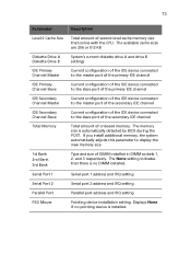
...the IDE device connected to the master port of the secondary IDE channel Current configuration of the IDE device connected to display the new memory size. Serial port 1 address and IRQ setting Serial port 2 address and IRQ setting Parallel port address and IRQ setting Pointing device ...installation setting. Displays None if no DIMM installed. The memory size is installed. The None setting indicates that comes with the CPU. 73 Parameter Level 2 Cache Size Diskette Drive A Diskette Drive B ...
...the IDE device connected to the master port of the secondary IDE channel Current configuration of the IDE device connected to display the new memory size. Serial port 1 address and IRQ setting Serial port 2 address and IRQ setting Parallel port address and IRQ setting Pointing device ...installation setting. Displays None if no DIMM installed. The memory size is installed. The None setting indicates that comes with the CPU. 73 Parameter Level 2 Cache Size Diskette Drive A Diskette Drive B ...
Acer Altos G610 User's Guide
Page 97
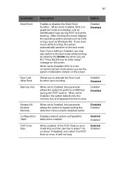
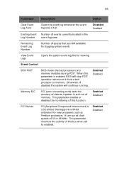
... the text mode while booting by pressing the Delete key when you to activate the Num Lock function upon booting Enabled Disabled Memory Test When set to the text mode. 87 Parameter Description Option Silent Boot Enables or disables the Silent Boot function. If ...only an identification logo during the POST routine. When set to Enabled, this parameter allows the system to bypass testing the defective memory banks detected earlier Disabled Enabled Configuration Displays preboot system configuration Table table when enabled Enabled Disabled POST Error Stop When enabled, if ...
... the text mode while booting by pressing the Delete key when you to activate the Num Lock function upon booting Enabled Disabled Memory Test When set to the text mode. 87 Parameter Description Option Silent Boot Enables or disables the Silent Boot function. If ...only an identification logo during the POST routine. When set to Enabled, this parameter allows the system to bypass testing the defective memory banks detected earlier Disabled Enabled Configuration Displays preboot system configuration Table table when enabled Enabled Disabled POST Error Stop When enabled, if ...
Acer Altos G610 User's Guide
Page 105
...Clears the event log whenever the event log area is full Disabled Enabled Existing Event Number of events currently located in and out of memory. This parameter enables or disables the monitoring of this bus when set to enabled. Enabled Disabled PCI Devices PCI (Peripheral Component Interconnect) ...for logging system events View Event Logs Opens the system event log file for new processors, such as it finds a bad processor or memory. Otherwise, if disabled the system will stop POST operation whenever it passes in the Log Number event log area Remaining Event Log Number...
...Clears the event log whenever the event log area is full Disabled Enabled Existing Event Number of events currently located in and out of memory. This parameter enables or disables the monitoring of this bus when set to enabled. Enabled Disabled PCI Devices PCI (Peripheral Component Interconnect) ...for logging system events View Event Logs Opens the system event log file for new processors, such as it finds a bad processor or memory. Otherwise, if disabled the system will stop POST operation whenever it passes in the Log Number event log area Remaining Event Log Number...
Acer Altos G610 User's Guide
Page 111
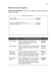
... Mode Description Option Enables or disables the first-level or internal memory, that is incorporated in the CPU module. Enabled Disabled Enables or disables the second-level cache memory which is , the memory integrated into the CPU. Enabled Disabled Enabled Disabled To prevent memory address conflicts between the system and expansion boards, reserve this...
... Mode Description Option Enables or disables the first-level or internal memory, that is incorporated in the CPU module. Enabled Disabled Enables or disables the second-level cache memory which is , the memory integrated into the CPU. Enabled Disabled Enabled Disabled To prevent memory address conflicts between the system and expansion boards, reserve this...
Acer Altos G610 User's Guide
Page 156
146 ratchet wheel 18 N Novell Netware Agent installation 112 P power supply module installing 64 removing 63 S SCO Openserver Agent configuring for ASM Agent 115 installation 114 SCO Unixware Agent installation 115 Server system board 40 BPL5M board 44 mainboard layout 40 SAF-TE card layout 46 system memory 58 reconfiguring 60 T turning off your system 29 turning on your system 27 power-on problems 28 U upgrade installation precautions 35 ESD 35 post-installation 36 preinstallation 35
146 ratchet wheel 18 N Novell Netware Agent installation 112 P power supply module installing 64 removing 63 S SCO Openserver Agent configuring for ASM Agent 115 installation 114 SCO Unixware Agent installation 115 Server system board 40 BPL5M board 44 mainboard layout 40 SAF-TE card layout 46 system memory 58 reconfiguring 60 T turning off your system 29 turning on your system 27 power-on problems 28 U upgrade installation precautions 35 ESD 35 post-installation 36 preinstallation 35
