Aspire 9300 / Aspire 7000 Service Guide
Page 8
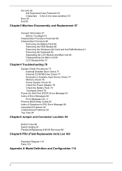
.../User Password 53 Characters 0-9,A-Z (not case sensitive) 53 Boot 55 Exit 56 Chapter3 Machine Disassembly and Replacement 57 General Information 57 Before You Begin 57 Disassembly Procedure Flowchart 58 Disassembly Procedure 60 Removing the Battery Pack 60 Removing the HDD Module 60 Removing the Wireless LAN Card... and the RAM Modules 61 Removing the Keyboard 63 Separating the LCD Module and Main Unit 64 Disassembling the Main Unit 65 LCD Disassembly 72 Chapter4 Troubleshooting 76 System Check Procedures 77 External Diskette Drive Check 77 External CD-ROM Drive Check 77 ...
.../User Password 53 Characters 0-9,A-Z (not case sensitive) 53 Boot 55 Exit 56 Chapter3 Machine Disassembly and Replacement 57 General Information 57 Before You Begin 57 Disassembly Procedure Flowchart 58 Disassembly Procedure 60 Removing the Battery Pack 60 Removing the HDD Module 60 Removing the Wireless LAN Card... and the RAM Modules 61 Removing the Keyboard 63 Separating the LCD Module and Main Unit 64 Disassembling the Main Unit 65 LCD Disassembly 72 Chapter4 Troubleshooting 76 System Check Procedures 77 External Diskette Drive Check 77 External CD-ROM Drive Check 77 ...
Aspire 9300 / Aspire 7000 Service Guide
Page 66
...The screws for the different components vary in length. The AC adaptor and all peripherals are unplugged. 3. Chapter 3 57 Chapter 3 Machine Disassembly and Replacement General Information This chapter contains step-by-step procedures on the wrong location, the long screws may cause irrecoverable damage to scrape ...careful not to the main board. When you fasten the screws on how to disassemble the notebook for each screw type. NOTE: There are several types of screws together during service disassembling. Group the same type of screws used to avoid mismatch when putting back the...
...The screws for the different components vary in length. The AC adaptor and all peripherals are unplugged. 3. Chapter 3 57 Chapter 3 Machine Disassembly and Replacement General Information This chapter contains step-by-step procedures on the wrong location, the long screws may cause irrecoverable damage to scrape ...careful not to the main board. When you fasten the screws on how to disassemble the notebook for each screw type. NOTE: There are several types of screws together during service disassembling. Group the same type of screws used to avoid mismatch when putting back the...
Aspire 9300 / Aspire 7000 Service Guide
Page 67
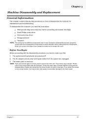
Description a SCW HEX NYL I#R-40/O#4-40 L5.5 b SCREW MACH WAFER M2*L4 NI c SCRW M2.5*6 ~ L-CASE + U-CASE d SCRW M2*L3 e SCRW M2.5*5 WAFER B-ZN ROHS f SCREW M2*L3 NYLOK CR 3+ Part No. 34.00015.081 86.T39V1.002 86.00D28.330 86.00D29.620 86.00D47.630 86.00E25.723 58 Chapter 3 Disassembly Procedure Flowchart The flowchart gives you a graphic representation on the entire disassembly and reassembly and instructs you how to remove the components. Screws List No.
Description a SCW HEX NYL I#R-40/O#4-40 L5.5 b SCREW MACH WAFER M2*L4 NI c SCRW M2.5*6 ~ L-CASE + U-CASE d SCRW M2*L3 e SCRW M2.5*5 WAFER B-ZN ROHS f SCREW M2*L3 NYLOK CR 3+ Part No. 34.00015.081 86.T39V1.002 86.00D28.330 86.00D29.620 86.00D47.630 86.00E25.723 58 Chapter 3 Disassembly Procedure Flowchart The flowchart gives you a graphic representation on the entire disassembly and reassembly and instructs you how to remove the components. Screws List No.
Aspire 9300 / Aspire 7000 Service Guide
Page 69
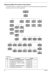
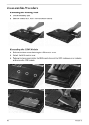
Detach the HDD module cover. 3. Release the two screws holding the HDD module then pull the HDD module as arrow indicates and remove the HDD module. 60 Chapter 3 Removing the HDD Module 1. Release the three screws fastening the HDD module cover. 2. Slide the battery latch, hold it then remove the battery. Disassembly Procedure Removing the Battery Pack 1. Unlock the battery pack. 2.
Detach the HDD module cover. 3. Release the two screws holding the HDD module then pull the HDD module as arrow indicates and remove the HDD module. 60 Chapter 3 Removing the HDD Module 1. Release the three screws fastening the HDD module cover. 2. Slide the battery latch, hold it then remove the battery. Disassembly Procedure Removing the Battery Pack 1. Unlock the battery pack. 2.
Aspire 9300 / Aspire 7000 Service Guide
Page 74
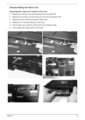
Chapter 3 65 Release the 27 screws holding the lower case. 5. Release the three screws securing the upper case. 4. Then separate the upper and the lower case. Disassembling the Main Unit Separating the Upper Case and the Lower Case 1. Release the connector lock and disconnect the touch pad FFC. 2. Release the connector lock and disconnect the function keyboard FFC. 3. Lift the upper case carefully and disconnect the lid switch cable. 6.
Chapter 3 65 Release the 27 screws holding the lower case. 5. Release the three screws securing the upper case. 4. Then separate the upper and the lower case. Disassembling the Main Unit Separating the Upper Case and the Lower Case 1. Release the connector lock and disconnect the touch pad FFC. 2. Release the connector lock and disconnect the function keyboard FFC. 3. Lift the upper case carefully and disconnect the lid switch cable. 6.
Aspire 9300 / Aspire 7000 Service Guide
Page 81
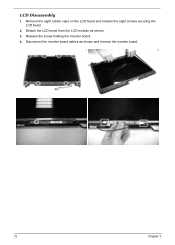
Disconnect the inverter board cables as shown. 3. LCD Disassembly 1. Release the screw holding the inverter board. 4. Remove the eight rubber caps on the LCD bezel and release the eight screws securing the LCD bezel. 2. Detach the LCD bezel from the LCD module as shown and remove the inverter board. 72 Chapter 3
Disconnect the inverter board cables as shown. 3. LCD Disassembly 1. Release the screw holding the inverter board. 4. Remove the eight rubber caps on the LCD bezel and release the eight screws securing the LCD bezel. 2. Detach the LCD bezel from the LCD module as shown and remove the inverter board. 72 Chapter 3
Aspire 9300 / Aspire 7000 Service Guide
Page 86
If any power sources. 4. T There are properly connected and secured; Disassemble and assemble the unit without any problem occurs, you fellow this chapter's instructions. Obtain the detailed fail symptoms as many as a guide for ... can perform visual inspection before you can check the following procedures as possible. 2. T All components appear normal. Verify the symptoms by attempting to test only Acer products. T There are intended to recreate, running the diagnostic tests or repeating the same operation. 3. Chapter 4 Troubleshooting Please use the following : T Power ...
If any power sources. 4. T There are properly connected and secured; Disassemble and assemble the unit without any problem occurs, you fellow this chapter's instructions. Obtain the detailed fail symptoms as many as a guide for ... can perform visual inspection before you can check the following procedures as possible. 2. T All components appear normal. Verify the symptoms by attempting to test only Acer products. T There are intended to recreate, running the diagnostic tests or repeating the same operation. 3. Chapter 4 Troubleshooting Please use the following : T Power ...


