
Aspire E500 User's Guide - EN
Page 19
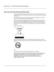
...OR DISPOSED OF ACCORDING TO LOCAL, STATE OR FEDERAL LAWS. Refer to www.acer.com for further information regarding Acer's environmental protection practices. To reduce the environmental impact of WEEE (Waste Electrical ...and Electronic Equipment) and minimize the volume of the global environment, please reuse and recycle. Do not throw this device. The manufacturing facilities and management meet the requirements of the ISO 14001 Environmental Management System (EMS). FOR LAMP-SPECIFIC...
...OR DISPOSED OF ACCORDING TO LOCAL, STATE OR FEDERAL LAWS. Refer to www.acer.com for further information regarding Acer's environmental protection practices. To reduce the environmental impact of WEEE (Waste Electrical ...and Electronic Equipment) and minimize the volume of the global environment, please reuse and recycle. Do not throw this device. The manufacturing facilities and management meet the requirements of the ISO 14001 Environmental Management System (EMS). FOR LAMP-SPECIFIC...
Aspire T650/E500 and Power F5 Service Guide
Page 3
...to change without the prior written permission of Acer Incorporated. Acer is a registered trademark of Intel Corporation. III Copyright Copyright © 2005 by any defect in this guide is subject to the contents hereof and specifically disclaims any warranties of merchantability or fitness ...for any particular purpose. Any Acer Incorporated software described in this publication may be reproduced, transmitted, transcribed, stored in a ...
...to change without the prior written permission of Acer Incorporated. Acer is a registered trademark of Intel Corporation. III Copyright Copyright © 2005 by any defect in this guide is subject to the contents hereof and specifically disclaims any warranties of merchantability or fitness ...for any particular purpose. Any Acer Incorporated software described in this publication may be reproduced, transmitted, transcribed, stored in a ...
Aspire T650/E500 and Power F5 Service Guide
Page 4
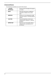
Alerts you to do specific actions relevant to the accomplishment of additional information related to any damage that appear on screen. NOTE WARNING CAUTION IMPORTANT Gives bits and pieces of procedures. Conventions The following conventions are used in this manual: SCREEN MESSAGES Denotes actual messages that might result from doing or not doing specific actions. Gives precautionary measures to avoid possible hardware or software problems. Reminds you to the current topic. IV
Alerts you to do specific actions relevant to the accomplishment of additional information related to any damage that appear on screen. NOTE WARNING CAUTION IMPORTANT Gives bits and pieces of procedures. Conventions The following conventions are used in this manual: SCREEN MESSAGES Denotes actual messages that might result from doing or not doing specific actions. Gives precautionary measures to avoid possible hardware or software problems. Reminds you to the current topic. IV

Aspire T650/E500 and Power F5 Service Guide
Page 6
...Setting 11 Connector Information 12 Aspire T650 Front Panel 17 Aspire E500 Front Pane 18 AcerPower F5 Front Panel 19 Aspire T650/E500, AcerPower F5 Rear Panel 20 System Peripherals 21 Acer eRecovery 23 Acer disc-to-disc recovery 25 Hardware Specifications and Configurations 26 Power ... and Replacement 55 General Information 56 Disassembly Procedure 57 Aspire T650 Standard Disassembly Procedure 58 Aspire T650 Standard Reassembly Procedure 66 Aspire E500 Standard Disassembly Procedure 75 Aspire E500 Standard Reassembly Procedure 83 AcerPower F5 Standard Disassembly Procedure ...
...Setting 11 Connector Information 12 Aspire T650 Front Panel 17 Aspire E500 Front Pane 18 AcerPower F5 Front Panel 19 Aspire T650/E500, AcerPower F5 Rear Panel 20 System Peripherals 21 Acer eRecovery 23 Acer disc-to-disc recovery 25 Hardware Specifications and Configurations 26 Power ... and Replacement 55 General Information 56 Disassembly Procedure 57 Aspire T650 Standard Disassembly Procedure 58 Aspire T650 Standard Reassembly Procedure 66 Aspire E500 Standard Disassembly Procedure 75 Aspire E500 Standard Reassembly Procedure 83 AcerPower F5 Standard Disassembly Procedure ...

Aspire T650/E500 and Power F5 Service Guide
Page 8
...-bit single-channel DDR/DDR2 SDRAM interface T SUpports one PCI Express x16 for Graphics Interface, fully compliant to the PCI Express Base Specification revision 1.0a T Full support for 3D primitive, Direct3D texture lighting, and OpenGL format for Intel to get fewer returns in Vertex ...CPU interface has been moved to address the overall platform graphic performance. These two models (Aspire T650/E500 & AcerPower F5) use ATI on the bottom of them. Chapter 1 System Specifications Overview All the new Socket-T motherboards come with dual channel provides faster processing speed and ...
...-bit single-channel DDR/DDR2 SDRAM interface T SUpports one PCI Express x16 for Graphics Interface, fully compliant to the PCI Express Base Specification revision 1.0a T Full support for 3D primitive, Direct3D texture lighting, and OpenGL format for Intel to get fewer returns in Vertex ...CPU interface has been moved to address the overall platform graphic performance. These two models (Aspire T650/E500 & AcerPower F5) use ATI on the bottom of them. Chapter 1 System Specifications Overview All the new Socket-T motherboards come with dual channel provides faster processing speed and ...

Aspire T650/E500 and Power F5 Service Guide
Page 13
... 4pin connector (CD-ROM Audio Input) T 1 3/4 pin CPU Fan connector T 1 3 pin System FAN connectors T 1 24pin/4pin ATX interface PS3/PS2 SPS connector T 1 2*4pin Intel FPIO specification Power Switch/Power State LED/HDD active LED T 1 2 pin LAN activity monitor connector T 2 reserved 2pin GPIO connector T Color management for on board connector 6 Chapter 1
... 4pin connector (CD-ROM Audio Input) T 1 3/4 pin CPU Fan connector T 1 3 pin System FAN connectors T 1 24pin/4pin ATX interface PS3/PS2 SPS connector T 1 2*4pin Intel FPIO specification Power Switch/Power State LED/HDD active LED T 1 2 pin LAN activity monitor connector T 2 reserved 2pin GPIO connector T Color management for on board connector 6 Chapter 1

Aspire T650/E500 and Power F5 Service Guide
Page 17
...) The parallel port allows connection of the 3 ports, B, C, and E provide users with both right&left channels individually. LAN Port The provided Internet connection is for specific port function definition. Users please refer to connect audio devices. Serial Port(COM1) Connects to audio input or audio output by changing the driver utility...
...) The parallel port allows connection of the 3 ports, B, C, and E provide users with both right&left channels individually. LAN Port The provided Internet connection is for specific port function definition. Users please refer to connect audio devices. Serial Port(COM1) Connects to audio input or audio output by changing the driver utility...

Aspire T650/E500 and Power F5 Service Guide
Page 33
... M1573 ITE 8712 Marvell 8EE8001 Build in ATI RC410 Build in ULI M1573 RTL 8110S ULI M1573 ATI RC410 ITE 8712 Specification Processor Type Slot Speed Bus Frequency Voltage Item Specification Intel Pentium 4 processor 775 Land Grid Array(LGA) Socket-T (LGA 775) Depends on CPU, which is local configured ... size BIOS ROM package Support protocol Boot from CD-ROM feature Support to LS-120 drive Support to BIOS boot block feature BIOS Password Control Specification AMI R01-A0 4MB 32-pin PLCC package PCIX 1.0,PCI 2.2,APM 1.2,VESA/DPMS (VBE/PM V1.1), SMBIOS 2.3, E-IDE 1.1, ACPI 1.0b,ESCD1.03, PnP ...
... M1573 ITE 8712 Marvell 8EE8001 Build in ATI RC410 Build in ULI M1573 RTL 8110S ULI M1573 ATI RC410 ITE 8712 Specification Processor Type Slot Speed Bus Frequency Voltage Item Specification Intel Pentium 4 processor 775 Land Grid Array(LGA) Socket-T (LGA 775) Depends on CPU, which is local configured ... size BIOS ROM package Support protocol Boot from CD-ROM feature Support to LS-120 drive Support to BIOS boot block feature BIOS Password Control Specification AMI R01-A0 4MB 32-pin PLCC package PCIX 1.0,PCI 2.2,APM 1.2,VESA/DPMS (VBE/PM V1.1), SMBIOS 2.3, E-IDE 1.1, ACPI 1.0b,ESCD1.03, PnP ...

Aspire T650/E500 and Power F5 Service Guide
Page 34
...) L2 Cache RAM size Depends on board Enable/Disable by BIOS Setup Chapter 1 27 VRM (Voltage Regulator Module) Function CPU VRM CPU VRM VRM Specification VRM10.1 VRM 9.0 Typical Voltage 0.8375~1.6v 1.1-1.85 Voltage Power Source 12 Voltage 12 Voltage Maximum Output 101A 70A Cache Memory Item... applicable to Error Correction Code (ECC) feature Memory module combinations 2 Slots 256 MB ~ 1GB 2GB 400/533/667 MHz 1.8 V 240-pin DIMM Yes Yes Specification You can install memory modules in write-back LAN Interface Item LAN Controller LAN Controller Resident Bus LAN Port Function Control...
...) L2 Cache RAM size Depends on board Enable/Disable by BIOS Setup Chapter 1 27 VRM (Voltage Regulator Module) Function CPU VRM CPU VRM VRM Specification VRM10.1 VRM 9.0 Typical Voltage 0.8375~1.6v 1.1-1.85 Voltage Power Source 12 Voltage 12 Voltage Maximum Output 101A 70A Cache Memory Item... applicable to Error Correction Code (ECC) feature Memory module combinations 2 Slots 256 MB ~ 1GB 2GB 400/533/667 MHz 1.8 V 240-pin DIMM Yes Yes Specification You can install memory modules in write-back LAN Interface Item LAN Controller LAN Controller Resident Bus LAN Port Function Control...

Aspire T650/E500 and Power F5 Service Guide
Page 35
...Enable/Disable by BIOS setup Diskette Drive Interface Item Diskette Drive Controller Diskette Drive Controller Resident Bus Supported Diskette Drive Formats Function Control Specification ULi M1573 LPC Bus 1.44MB, 2.88MB format and slim type diskette drive Enable/Disable by BIOS Setup Serial Port Item Serial port...Serial port location 16550 UART support Connector type Optional serial port I/O address (via BIOS Setup) Optional serial port IRQ (via BIOS Setup) Specification Build-in ITE 8712 LPC Bus 1 Rear Panel Yes 9-pin D-type female connector 3F8h 2F8h 3E8h 2E8h IRQ4 IRQ3 USB Port Item ...
...Enable/Disable by BIOS setup Diskette Drive Interface Item Diskette Drive Controller Diskette Drive Controller Resident Bus Supported Diskette Drive Formats Function Control Specification ULi M1573 LPC Bus 1.44MB, 2.88MB format and slim type diskette drive Enable/Disable by BIOS Setup Serial Port Item Serial port...Serial port location 16550 UART support Connector type Optional serial port I/O address (via BIOS Setup) Optional serial port IRQ (via BIOS Setup) Specification Build-in ITE 8712 LPC Bus 1 Rear Panel Yes 9-pin D-type female connector 3F8h 2F8h 3E8h 2E8h IRQ4 IRQ3 USB Port Item ...

Aspire T650/E500 and Power F5 Service Guide
Page 36
... Power Button PS2 Keyboard USB Keyboard LAN WOR (wake on I/O Adapters 29 USB Port Location Item USB Class Specification Rear : 4 On-board header : 4 Support legacy keyboard for legacy mode Wake-up Event Item Power On/ Wake-Up Event Description T Power Button: S1/S3/S4/...
... Power Button PS2 Keyboard USB Keyboard LAN WOR (wake on I/O Adapters 29 USB Port Location Item USB Class Specification Rear : 4 On-board header : 4 Support legacy keyboard for legacy mode Wake-up Event Item Power On/ Wake-Up Event Description T Power Button: S1/S3/S4/...
Aspire T650/E500 and Power F5 Service Guide
Page 39
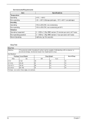
Environmental Requirements Item Temperature Operating Non-operating Humidity Operating Non-operating Vibration Operating (unpacked) Non-operating (packed) Shock Operating Specifications +5°C ~ +35°C -20 ~ +60°C (Storage package), -10°C~+60°C (un-package) 15% to 80% RH, non-condensing 10% to 90% RH, non-... edges, six surfaces 32 Chapter 1 Test Standard Package Cross Weight Drop Height Not of withstanding, with no physical or functional demage, mechanical impact from height-specific drops.
Environmental Requirements Item Temperature Operating Non-operating Humidity Operating Non-operating Vibration Operating (unpacked) Non-operating (packed) Shock Operating Specifications +5°C ~ +35°C -20 ~ +60°C (Storage package), -10°C~+60°C (un-package) 15% to 80% RH, non-condensing 10% to 90% RH, non-... edges, six surfaces 32 Chapter 1 Test Standard Package Cross Weight Drop Height Not of withstanding, with no physical or functional demage, mechanical impact from height-specific drops.
Aspire T650/E500 and Power F5 Service Guide
Page 40
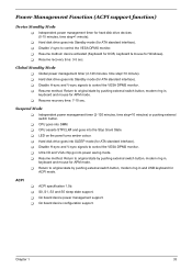
... management timer (2-120 minutes, time step=10 minutes) or pushing external switch button. T Ultra I/O and VGA chip go into the Stop Grant State. ACPI T ACPI specification 1.0b. T Disable V-sync to control the VESA DPMS monitor. T Resume recovery time: 3-5 sec. Global Standby Mode T Global power management timer (2-120 minutes, time step=10...
... management timer (2-120 minutes, time step=10 minutes) or pushing external switch button. T Ultra I/O and VGA chip go into the Stop Grant State. ACPI T ACPI specification 1.0b. T Disable V-sync to control the VESA DPMS monitor. T Resume recovery time: 3-5 sec. Global Standby Mode T Global power management timer (2-120 minutes, time step=10...

Aspire T650/E500 and Power F5 Service Guide
Page 54
... VGA PCI IDE BusMaster PCI/VGA Palette Snoop [Enabled] [Enabled] [Disabled] Help Item YES: Assign IRQ to keep this item at "Disabled" unless a video device specifically requires the setting enabled upon installation. Copyright (C) 1985-2004, American Megatrends, Inc. Users are recommended to PCI VGA card if card requests IRQ. This option...
... VGA PCI IDE BusMaster PCI/VGA Palette Snoop [Enabled] [Enabled] [Disabled] Help Item YES: Assign IRQ to keep this item at "Disabled" unless a video device specifically requires the setting enabled upon installation. Copyright (C) 1985-2004, American Megatrends, Inc. Users are recommended to PCI VGA card if card requests IRQ. This option...
Aspire T650/E500 and Power F5 Service Guide
Page 57
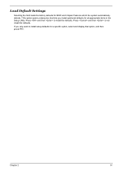
Press and then to install the defaults. detects. Press and then to not install the defaults. Chapter 2 51 Load Default Settings Selecting the field loads the factory defaults for a specific option, select and display that option, and then press. If you install optimized defaults for all appropriate items in the Setup Utility. THis option opens a dialog box that lets you only want to install setup dafaults for BIOS and Chipset Features which the system automatically.
Press and then to install the defaults. detects. Press and then to not install the defaults. Chapter 2 51 Load Default Settings Selecting the field loads the factory defaults for a specific option, select and display that option, and then press. If you install optimized defaults for all appropriate items in the Setup Utility. THis option opens a dialog box that lets you only want to install setup dafaults for BIOS and Chipset Features which the system automatically.