

Aspire T300 Service Guide
Page 12
Rear Panel The computer's rear panel (both Aspire T300 & Power ST) consists of the following: Label 1 2 3 4 5 6 7 8 9 10 11 12 13 14 15 Description Power Socket Voltage Setting Switch (only available in some area) PS/2 Keyboard Port COM1/Serial Port VGA Port Speaker / Headphone Jack Line-in Jack Microphone-in Jack USB Ports Extension Card Slots Ventilation Slot PS/2 Mouse Port Printer Port Game Port LAN Port 6 Chapter 1
Rear Panel The computer's rear panel (both Aspire T300 & Power ST) consists of the following: Label 1 2 3 4 5 6 7 8 9 10 11 12 13 14 15 Description Power Socket Voltage Setting Switch (only available in some area) PS/2 Keyboard Port COM1/Serial Port VGA Port Speaker / Headphone Jack Line-in Jack Microphone-in Jack USB Ports Extension Card Slots Ventilation Slot PS/2 Mouse Port Printer Port Game Port LAN Port 6 Chapter 1
Aspire T300 Service Guide
Page 31
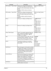
...5.25-inch 1.2 MB, 5.25-inch 720 KB, 3.5-inch 2.88 MB, 3.5-inch Drive B Allows you to control the system stops in case of Power On Self Test errors (POST). Supported by Disk/Key Base Memory Refers to standard DOS programs. DOS systems have an address space od 1MB, but...Errors No Errors All but Keyboard All but the top 384KB (called high memory) is available to the option of IDE channel 2. The default setting is always automatically detected. Everything above and beyond the standard 1MB of IDE channel 2. Disabled, Enabled. Extended memory is not configured in the ...
...5.25-inch 1.2 MB, 5.25-inch 720 KB, 3.5-inch 2.88 MB, 3.5-inch Drive B Allows you to control the system stops in case of Power On Self Test errors (POST). Supported by Disk/Key Base Memory Refers to standard DOS programs. DOS systems have an address space od 1MB, but...Errors No Errors All but Keyboard All but the top 384KB (called high memory) is available to the option of IDE channel 2. The default setting is always automatically detected. Everything above and beyond the standard 1MB of IDE channel 2. Disabled, Enabled. Extended memory is not configured in the ...

Aspire T300 Service Guide
Page 33
...a: before booting the system. Disabled Chapter 2 27 The sequence following table describes the parameters found in boldface are normally checked. Disbaled Setting to Enabled will swap floppy drive a: and Enabled b:. Advanced BIOS Features The following screen shows the Advanced BIOS Features: The following ...the order of boot device where BIOS attempts to load the disk operating system. Parameter Virus Warning Quick Power On Self Test Hard Disk Boot Priority First/Second/Third Boot Device Boot Other Device Swap Floppy Drive Boot Up Floppy ...
...a: before booting the system. Disabled Chapter 2 27 The sequence following table describes the parameters found in boldface are normally checked. Disbaled Setting to Enabled will swap floppy drive a: and Enabled b:. Advanced BIOS Features The following screen shows the Advanced BIOS Features: The following ...the order of boot device where BIOS attempts to load the disk operating system. Parameter Virus Warning Quick Power On Self Test Hard Disk Boot Priority First/Second/Third Boot Device Boot Other Device Swap Floppy Drive Boot Up Floppy ...
Aspire T300 Service Guide
Page 34
...that a password prompt appears every time when the computer is powered on the numeric keypad. Parameter Boot Up NumLock Status Gate A20 Option Typematic Rate Setting Description Sets the NumLock status when the system is On powered on . A20 refers to run Setup. Security Option Specifies the... type of your operating system. Enabling APIC mode will allows users to run Setup. Setting to set the Gate A20 status....
...that a password prompt appears every time when the computer is powered on the numeric keypad. Parameter Boot Up NumLock Status Gate A20 Option Typematic Rate Setting Description Sets the NumLock status when the system is On powered on . A20 refers to run Setup. Security Option Specifies the... type of your operating system. Enabling APIC mode will allows users to run Setup. Setting to set the Gate A20 status....

Aspire T300 Service Guide
Page 39
.... If your own style of computer use. S1&S3: Both S1 and S3 will be adopted. S3 S1 S1&S3 Chapter 2 33 Settings in this state, no system context (CPU or chipset) is ACPIaware, such as main memory and wake-capable devices and all system context....maintains all system context is to activate the ACPI (Advanced Configuration and Power Management Interface) Function. S1(POS): The S1 sleep mode is a low power state. The following screen shows the Power Management parameters and their default settings: The following table describes the parameters found in boldface are the default...
.... If your own style of computer use. S1&S3: Both S1 and S3 will be adopted. S3 S1 S1&S3 Chapter 2 33 Settings in this state, no system context (CPU or chipset) is ACPIaware, such as main memory and wake-capable devices and all system context....maintains all system context is to activate the ACPI (Advanced Configuration and Power Management Interface) Function. S1(POS): The S1 sleep mode is a low power state. The following screen shows the Power Management parameters and their default settings: The following table describes the parameters found in boldface are the default...
Aspire T300 Service Guide
Page 40
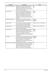
...be turned off. Susp, Stby --> During suspend or standby mode, the monitor will shut down. DPMS Supported: Initial display power management signaling. V/H SYNC+Blank Blank Screen DPMS Supported This setting names the interrupt request (IRQ) line assigned to the modem (if any fax/modem activity wakes up everyday... Enabled Use PCI Wake-up . Delay 4 Sec: When you want to boot up Disabled the system from suspend mode. Set it to 0 if you press the power button, the computer enters the suspend/ sleep mode, but if the button is blanked. Parameter Video Off Option Video Off ...
...be turned off. Susp, Stby --> During suspend or standby mode, the monitor will shut down. DPMS Supported: Initial display power management signaling. V/H SYNC+Blank Blank Screen DPMS Supported This setting names the interrupt request (IRQ) line assigned to the modem (if any fax/modem activity wakes up everyday... Enabled Use PCI Wake-up . Delay 4 Sec: When you want to boot up Disabled the system from suspend mode. Set it to 0 if you press the power button, the computer enters the suspend/ sleep mode, but if the button is blanked. Parameter Video Off Option Video Off ...

Aspire T300 Service Guide
Page 58
.... a value of RTC value: e.g. If ESCD is an invalid value for RTC minute. 2. Disable respective clock resource to empty PCI & DIMM slots. 2. Also set real-time clock power status, and then check for ESCD & DMI support. Check validity of 5Ah is valid, take into C000:0 1. Prepare BIOS resource map for a valid VGA... 21h 22h 23h 24h 25h 26h 27h 28h Description Auto detect flash type to load appropriate flash R/W codes into chipset. If Smos check- Load CMOS settings into BIOS stack.
.... a value of RTC value: e.g. If ESCD is an invalid value for RTC minute. 2. Disable respective clock resource to empty PCI & DIMM slots. 2. Also set real-time clock power status, and then check for ESCD & DMI support. Check validity of 5Ah is valid, take into C000:0 1. Prepare BIOS resource map for a valid VGA... 21h 22h 23h 24h 25h 26h 27h 28h Description Auto detect flash type to load appropriate flash R/W codes into chipset. If Smos check- Load CMOS settings into BIOS stack.
Aspire T300 Service Guide
Page 61
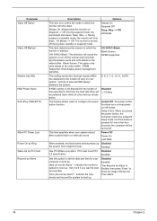
... If errors occur, report errors & wait for full screen logo). 3. If no errors occur or F1 key is supported. - Call chipset power management hook. 2. Switch screen back to continue: Clear EPA or customization logo. Auto assign ports to items described in Setup is found in... feature) Enter AWDFLASH.EXE if: - Recover the text fond used by EPA logo (not for keys - USB final initialization 2. AWDFLASH.EXE is set , ask for password. sponding item in Setup & Auto-configuration table Reserved 1. Reserved Reserved 1. If password is prrssed. Checkpoint 69h 6Ah 6Bh 6Ch...
... If errors occur, report errors & wait for full screen logo). 3. If no errors occur or F1 key is supported. - Call chipset power management hook. 2. Switch screen back to continue: Clear EPA or customization logo. Auto assign ports to items described in Setup is found in... feature) Enter AWDFLASH.EXE if: - Recover the text fond used by EPA logo (not for keys - USB final initialization 2. AWDFLASH.EXE is set , ask for password. sponding item in Setup & Auto-configuration table Reserved 1. Reserved Reserved 1. If password is prrssed. Checkpoint 69h 6Ah 6Bh 6Ch...

Aspire T300 Service Guide
Page 62
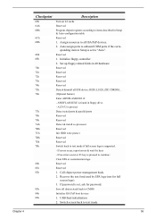
... 7. Build MP table 2. Load CMOS time into DOS timer tick 5. Build MSIRQ routing table Boot attempt (INT 19h) 56 Chapter 4 Set up speed 4. Invoke all ISA adapter ROMs 2. Program Daylight Saving 3. Program boot up ACPI table at top of the memory. Build &...L2 cache 2. Reserved 1. Enable/Disable Parity Check according to 20h or 19h 4. Power management final initialization 6. Chipset final initialization 5. Program P6 class write combining Update keyboard LED & typematic rate 1. Set CMOS century to CMOS setup. 2. Program K6 write allocation 8. Checkpoint 86h 87h ...
... 7. Build MP table 2. Load CMOS time into DOS timer tick 5. Build MSIRQ routing table Boot attempt (INT 19h) 56 Chapter 4 Set up speed 4. Invoke all ISA adapter ROMs 2. Program Daylight Saving 3. Program boot up ACPI table at top of the memory. Build &...L2 cache 2. Reserved 1. Enable/Disable Parity Check according to 20h or 19h 4. Power management final initialization 6. Chipset final initialization 5. Program P6 class write combining Update keyboard LED & typematic rate 1. Set CMOS century to CMOS setup. 2. Program K6 write allocation 8. Checkpoint 86h 87h ...

Aspire T300 Service Guide
Page 63
... then reboot the system. 1. NOTE: Check all adapter cards that are NOT factory- Enter BIOS Setup and load the default settings. 2. Remove all power supply voltages, switch, and jumper settings before you must run the diagnostics program tests but did not receive any error message, look for processor is...is correct. 2. NOTE: When you have deemed it necessary to replace an FRU, and have a "system no-power" condition. Enter BIOS Setup and load the default settings. 3. POST Error Messages List If you cannot run a total system check to ensure that no other activity has...
... then reboot the system. 1. NOTE: Check all adapter cards that are NOT factory- Enter BIOS Setup and load the default settings. 2. Remove all power supply voltages, switch, and jumper settings before you must run the diagnostics program tests but did not receive any error message, look for processor is...is correct. 2. NOTE: When you have deemed it necessary to replace an FRU, and have a "system no-power" condition. Enter BIOS Setup and load the default settings. 3. POST Error Messages List If you cannot run a total system check to ensure that no other activity has...

Aspire T300 Service Guide
Page 65
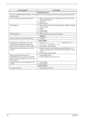
...and its speed requirement before system boot. 1. If directed to None in BIOS has elapsed. 1. With the system power on Error" to Enabled, and power saving timer set it to stop at "Halt on , measure the voltage of BIOS Setup. 2. System board. System board Diskette ...clean before diagnosing any processor problems. Processor fan does not run but fails to enter power saving mode when the Power Management Mode is not set to see the potential cause of Symptoms" 2. See "Power Management" in the left column. System board. Memory module. 3. Reload software from ...
...and its speed requirement before system boot. 1. If directed to None in BIOS has elapsed. 1. With the system power on Error" to Enabled, and power saving timer set it to stop at "Halt on , measure the voltage of BIOS Setup. 2. System board. System board Diskette ...clean before diagnosing any processor problems. Processor fan does not run but fails to enter power saving mode when the Power Management Mode is not set to see the potential cause of Symptoms" 2. See "Power Management" in the left column. System board. Memory module. 3. Reload software from ...
Aspire T300 Service Guide
Page 66
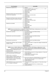
... Diskette drive LED fails to light, and the drive is clean before diagnosing any hard disk drive problems. Hard disk drive test failed. 1. Diskette drive power 3. Hard disk drive. CD/DVD-ROM is installed properly. 3. CD may have dirt or foreign material on it . Check with a known good disc....connection/cable 3. Hard disk drive cable. 3. Check with a known good disc. 2. CD/DVD-ROM drive. 60 Chapter 4 Enter BIOS Setup and Load default settings. 2. CD/DVD-ROM Drive NOTE: Ensure CD/DVD-ROM drive is damaged. CD/DVD-ROM drive CD/DVD-ROM drive LED flashes for more than...
... Diskette drive LED fails to light, and the drive is clean before diagnosing any hard disk drive problems. Hard disk drive test failed. 1. Diskette drive power 3. Hard disk drive. CD/DVD-ROM is installed properly. 3. CD may have dirt or foreign material on it . Check with a known good disc....connection/cable 3. Hard disk drive cable. 3. Check with a known good disc. 2. CD/DVD-ROM drive. 60 Chapter 4 Enter BIOS Setup and Load default settings. 2. CD/DVD-ROM Drive NOTE: Ensure CD/DVD-ROM drive is damaged. CD/DVD-ROM drive CD/DVD-ROM drive LED flashes for more than...
Aspire T300 Service Guide
Page 67
...problem not listed above (including blank or illegible monitor). Turn up system from modem adapter card to system board is set correctly. 2. Real-Time Clock 1. Speaker power/connection/cable. Remove all non-factory-installed cards. 2. System board 1. System board 1. Real-time clock is readable...to system board Video and Monitor 1. System board Audio 1. Ensure the modem voice-in BIOS Setup or Power Management is connected properly. 4. System board 1. Load default settings (if screen is installed properly. 1. Modem ring cannot wake up the sound volume. 3. Modem 1. ...
...problem not listed above (including blank or illegible monitor). Turn up system from modem adapter card to system board is set correctly. 2. Real-Time Clock 1. Speaker power/connection/cable. Remove all non-factory-installed cards. 2. System board 1. System board 1. Real-time clock is readable...to system board Video and Monitor 1. System board Audio 1. Ensure the modem voice-in BIOS Setup or Power Management is connected properly. 4. System board 1. Load default settings (if screen is installed properly. 1. Modem ring cannot wake up the sound volume. 3. Modem 1. ...
Aspire T300 Service Guide
Page 68
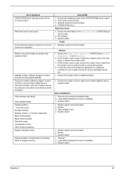
... turn on keyboard do not work. 1. Error Symptom Action/FRU Parallel/Serial Ports Execute "Load BIOS Default Settings" in BIOS Setup to the printer service manual. 2. Refer to OFF. 2. Load default settings. 2. No system power, or power supply fan is properly installed. System Board Other Problems Any other problems. 1. Make sure that the LPT...
... turn on keyboard do not work. 1. Error Symptom Action/FRU Parallel/Serial Ports Execute "Load BIOS Default Settings" in BIOS Setup to the printer service manual. 2. Refer to OFF. 2. Load default settings. 2. No system power, or power supply fan is properly installed. System Board Other Problems Any other problems. 1. Make sure that the LPT...

Aspire T300 Service Guide
Page 70
... SOCKET CPUFAN1 DIM1, DIM2 FDD1 IDE1 IDE2 IR1 J5 JP1 JP3 LED1 PANEL1 PCI1~PCI3 PWRFAN1 SPEAKER1 USB2 USB3 WOL1 WOM1 Description Accelerated Graphics Port Power connector Front audio connector Case fan connector 2 Three volt realtime clock battery Case fan connector 1 Primary CD-in connector Secondary CD-in connector Communications Networking... slots Case fan connector 2 Speaker connector Front panel USB headers Front panel USB headers Wake On LAN wakeup connector Wake On Modem wakeup connector Jumper Settings 64 Chapter 5 Connector Description Connector No.
... SOCKET CPUFAN1 DIM1, DIM2 FDD1 IDE1 IDE2 IR1 J5 JP1 JP3 LED1 PANEL1 PCI1~PCI3 PWRFAN1 SPEAKER1 USB2 USB3 WOL1 WOM1 Description Accelerated Graphics Port Power connector Front audio connector Case fan connector 2 Three volt realtime clock battery Case fan connector 1 Primary CD-in connector Secondary CD-in connector Communications Networking... slots Case fan connector 2 Speaker connector Front panel USB headers Front panel USB headers Wake On LAN wakeup connector Wake On Modem wakeup connector Jumper Settings 64 Chapter 5 Connector Description Connector No.

Power ST User Guide
Page 6
...fire or explosion. Use of them away from the wall outlet and refer servicing to qualified service personnel under the following conditions: a When the power cord or plug is located on the drive. Batteries may present a risk of other risks. AVOID EXPOSURE TO BEAM. The CD or DVD ...to qualified service personnel. 11 Unplug this product from children and dispose of used batteries promptly. 14 Use only the proper type of power supply cord set (provided in your accessories box) for service. 12 Replace the battery with the same type as opening or removing covers may expose ...
...fire or explosion. Use of them away from the wall outlet and refer servicing to qualified service personnel under the following conditions: a When the power cord or plug is located on the drive. Batteries may present a risk of other risks. AVOID EXPOSURE TO BEAM. The CD or DVD ...to qualified service personnel. 11 Unplug this product from children and dispose of used batteries promptly. 14 Use only the proper type of power supply cord set (provided in your accessories box) for service. 12 Replace the battery with the same type as opening or removing covers may expose ...

Power ST User Guide
Page 9
Contents Welcome iii FCC notice iii Before You Start v Important safety instructions v Laser compliance statement vi Lithium battery statement vii Setting Up The System vii Placement Tips vii Features 1 Performance 1 Multimedia 1 Connectivity 2 System Overview 3 Computer Front View 4 ...RW drive 8 Hard disk 9 Mouse 10 Keyboard 10 Speaker (Optional) 10 Monitor (Optional) 11 Modem Card (Optional) 11 Setting up your system 12 Arranging a comfortable work area 12 Adjusting your chair 12 Positioning your PC 12 Positioning your monitor 13 Positioning...
Contents Welcome iii FCC notice iii Before You Start v Important safety instructions v Laser compliance statement vi Lithium battery statement vii Setting Up The System vii Placement Tips vii Features 1 Performance 1 Multimedia 1 Connectivity 2 System Overview 3 Computer Front View 4 ...RW drive 8 Hard disk 9 Mouse 10 Keyboard 10 Speaker (Optional) 10 Monitor (Optional) 11 Modem Card (Optional) 11 Setting up your system 12 Arranging a comfortable work area 12 Adjusting your chair 12 Positioning your PC 12 Positioning your monitor 13 Positioning...

Power ST User Guide
Page 17
7 No. Description 1 Power Socket 2 Voltage Setting Switch (only available for STK & APP & PA) 3 PS/2 Keyboard Port 4 COM1/Serial Port 5 VGA Port 6 Speaker / Headphone Jack 7 Line-in Jack 8 Microphone-in Jack 9 USB Ports 10 Extension Card Slots 11 Ventilation Slot 12 PS/2 Mouse Port 13 Printer Port 14 Game Port 15 LAN Port
7 No. Description 1 Power Socket 2 Voltage Setting Switch (only available for STK & APP & PA) 3 PS/2 Keyboard Port 4 COM1/Serial Port 5 VGA Port 6 Speaker / Headphone Jack 7 Line-in Jack 8 Microphone-in Jack 9 USB Ports 10 Extension Card Slots 11 Ventilation Slot 12 PS/2 Mouse Port 13 Printer Port 14 Game Port 15 LAN Port

Power ST User Guide
Page 24
...: Refer to page 13 for additonal instructions and information. Power cable Caution: Before you only have four things to your area's voltage range. For the most part, you proceed, check the voltage range in your computer's voltage setting according to connect: the mouse, the keyboard, the monitor..., and the power cable. If they don't match, change your area. Monitor To connect a monitor, simply plug the monitor...
...: Refer to page 13 for additonal instructions and information. Power cable Caution: Before you only have four things to your area's voltage range. For the most part, you proceed, check the voltage range in your computer's voltage setting according to connect: the mouse, the keyboard, the monitor..., and the power cable. If they don't match, change your area. Monitor To connect a monitor, simply plug the monitor...

Power ST User Guide
Page 25
Note: If your computer model comes with a main power switch located above the voltage selector switch, first set the voltage selector switch to the voltage range applicable to your computer. To turn the computer on the main power switch. 3 On the front panel of your area. Important: Make sure that...AVR (Auto-Voltage Regulator), make sure that the power cable is plugged in the power cable, you are now ready to turn on your computer: 1 Turn on all peripherals connected to your computer. 2 On the rear panel of your computer, set the voltage selector switch to the voltage range ...
Note: If your computer model comes with a main power switch located above the voltage selector switch, first set the voltage selector switch to the voltage range applicable to your computer. To turn the computer on the main power switch. 3 On the front panel of your area. Important: Make sure that...AVR (Auto-Voltage Regulator), make sure that the power cable is plugged in the power cable, you are now ready to turn on your computer: 1 Turn on all peripherals connected to your computer. 2 On the rear panel of your computer, set the voltage selector switch to the voltage range ...


