
TravelMate 4100/4600 Service Guide
Page 6
... Main 47 Advanced 49 Security 51 Boot 54 Exit 55 Chapter 3 Machine Disassembly and Replacement 56 General Information 57 Disassembly Procedure Flowchart 59 Removing the Battery Pack 61 Removing the HDD 62 Removing the Memory and the Wireless LAN Card 62 Removing the Thermal Module and CPU 63 Removing the ODD...
... Main 47 Advanced 49 Security 51 Boot 54 Exit 55 Chapter 3 Machine Disassembly and Replacement 56 General Information 57 Disassembly Procedure Flowchart 59 Removing the Battery Pack 61 Removing the HDD 62 Removing the Memory and the Wireless LAN Card 62 Removing the Thermal Module and CPU 63 Removing the ODD...

TravelMate 4100/4600 Service Guide
Page 7
... External CD-ROM Drive Check 74 Keyboard or Auxiliary Input Device Check 74 Memory Check 75 Power System Check 75 Power Adapter 76 Check the Battery Pack 77 Touchpad Check 77 PhoenixBIOS POST Tasks and Beep Codes 78 Index of Error Messages 79 POST Code 82 Index of Symptom-to-FRU...
... External CD-ROM Drive Check 74 Keyboard or Auxiliary Input Device Check 74 Memory Check 75 Power System Check 75 Power Adapter 76 Check the Battery Pack 77 Touchpad Check 77 PhoenixBIOS POST Tasks and Beep Codes 78 Index of Error Messages 79 POST Code 82 Index of Symptom-to-FRU...

TravelMate 4100/4600 Service Guide
Page 10
Battery T T T 8-cell of Li-ion battery pack, (4400mAh,65W) 4-cell of Li-ion battery pack, (2200mAh,32W) 65W AC adaptor 19V 3.42A Weight (with battery) T 6.6 lbs (3 kg) Dimensions T 360(W) x 273(D) x 27/32(H) mm Environment T Temperature T Operating: 5o C ~ 35o C T Non-operating: -20o C ~ 65o C T Humidity ( non-condensing) T Operating: 20% ~ 80% RH T Non-operating: 20% ~ 80% RH Chapter 1 3
Battery T T T 8-cell of Li-ion battery pack, (4400mAh,65W) 4-cell of Li-ion battery pack, (2200mAh,32W) 65W AC adaptor 19V 3.42A Weight (with battery) T 6.6 lbs (3 kg) Dimensions T 360(W) x 273(D) x 27/32(H) mm Environment T Temperature T Operating: 5o C ~ 35o C T Non-operating: -20o C ~ 65o C T Humidity ( non-condensing) T Operating: 20% ~ 80% RH T Non-operating: 20% ~ 80% RH Chapter 1 3

TravelMate 4100/4600 Service Guide
Page 14
... 2.5VSUS +2.5V +1.8V MVREF_DM SMDDR_VTERM 1.5V_S5 1.5V / 1.05V / 1.8V +1.5V Page : 37 AGP_VCC (+1.5V) 1.2VCCT VTT CPU CORE Page : 34 +1.2V Page : 38 BATTERY CHARGER Page : 39 BATTERY SELECT Page : 40 VCC_CORE VGA_CORE 2.5V_VGA CLOCK GEN ICS ICS954201 Page : 2 Centrino DOTHAN CELEROM-M CRANE2 ( ZL3 ) INTEL Mobile_479 CPU Page : 3 , 4 HOST BUS 533MHz HOST...
... 2.5VSUS +2.5V +1.8V MVREF_DM SMDDR_VTERM 1.5V_S5 1.5V / 1.05V / 1.8V +1.5V Page : 37 AGP_VCC (+1.5V) 1.2VCCT VTT CPU CORE Page : 34 +1.2V Page : 38 BATTERY CHARGER Page : 39 BATTERY SELECT Page : 40 VCC_CORE VGA_CORE 2.5V_VGA CLOCK GEN ICS ICS954201 Page : 2 Centrino DOTHAN CELEROM-M CRANE2 ( ZL3 ) INTEL Mobile_479 CPU Page : 3 , 4 HOST BUS 533MHz HOST...

TravelMate 4100/4600 Service Guide
Page 16
... only) button/indicator 6 Wireless Press to Universal Serial Bus (USB) 2.0 devices (e.g., USB mouse, USB camera). Chapter 1 9 Latch Locks and releases the lid. Description 4 Battery indicator Lights when the battery is on page 10 # Icon Item Description # Icon Item # 1## #N#/A IIIcccIoocoIcnoonnnn IteImtIetImetSempemakerIstem 2 Infrared port # Icon Item # Icon Item Description DesLcerDiftpeatnisocdnrriipghtDtiosepnesackDrerispedtDesileicovsercnrrisipptetirtoeinooaundio output. # Item "LDaeusnccrhipktieoyns" on...
... only) button/indicator 6 Wireless Press to Universal Serial Bus (USB) 2.0 devices (e.g., USB mouse, USB camera). Chapter 1 9 Latch Locks and releases the lid. Description 4 Battery indicator Lights when the battery is on page 10 # Icon Item Description # Icon Item # 1## #N#/A IIIcccIoocoIcnoonnnn IteImtIetImetSempemakerIstem 2 Infrared port # Icon Item # Icon Item Description DesLcerDiftpeatnisocdnrriipghtDtiosepnesackDrerispedtDesileicovsercnrrisipptetirtoeinooaundio output. # Item "LDaeusnccrhipktieoyns" on...

TravelMate 4100/4600 Service Guide
Page 20
...'s hard disk (seDcueresdcrbiypatisocnrew). 2 AcerMedia bay release Unlatches the AcerMedia drive for TravelMate 4600 only) 4 Battery release latch Unlatches the battery to remove the battery pack. 5 Battery bay Houses the computer's battery pack. 6 Battery lock Locks the battery in place. 7 Cooling fan Helps keep the computer cool. latch (for TravelMate 4600 only) 3 AcerMedia bay Houses an AcerMedia drive module. (for...
...'s hard disk (seDcueresdcrbiypatisocnrew). 2 AcerMedia bay release Unlatches the AcerMedia drive for TravelMate 4600 only) 4 Battery release latch Unlatches the battery to remove the battery pack. 5 Battery bay Houses the computer's battery pack. 6 Battery lock Locks the battery in place. 7 Cooling fan Helps keep the computer cool. latch (for TravelMate 4600 only) 3 AcerMedia bay Houses an AcerMedia drive module. (for...

TravelMate 4100/4600 Service Guide
Page 24
Icon Item Power Icon Function Battery indicator Description Lights when the computer is charging. 2. Chapter 1 17 Charging: the light shows amber when the battery is on. Lights when the battery is closed, the state or features can still be seen. In addition, there are two indicators at the front panel. Fully charged: light shows green when in AC mode. Description 1. Even when the cover is being charged.
Icon Item Power Icon Function Battery indicator Description Lights when the computer is charging. 2. Chapter 1 17 Charging: the light shows amber when the battery is on. Lights when the battery is closed, the state or features can still be seen. In addition, there are two indicators at the front panel. Fully charged: light shows green when in AC mode. Description 1. Even when the cover is being charged.

TravelMate 4100/4600 Service Guide
Page 29
... to Description "Launch manage the settings and security keys" o Acer eSettinof gyour PC. "Launch keys" o Acer eSetting "La"uLnacuhnkcehyks"eyosn" poangep Icon Item AAcAceceerr reeSeeSttiSnegetttitningIgt is designed for easy access to control all AceePorweerMPanoagw emeentrMyouar PnC'as pgoweermscheemnestand maximise battery life. Acer ePowerManagement Acer ePowerManagement Acer eRecovery Acer eRecovery It backs up your files preventing data loss...
... to Description "Launch manage the settings and security keys" o Acer eSettinof gyour PC. "Launch keys" o Acer eSetting "La"uLnacuhnkcehyks"eyosn" poangep Icon Item AAcAceceerr reeSeeSttiSnegetttitningIgt is designed for easy access to control all AceePorweerMPanoagw emeentrMyouar PnC'as pgoweermscheemnestand maximise battery life. Acer ePowerManagement Acer ePowerManagement Acer eRecovery Acer eRecovery It backs up your files preventing data loss...

TravelMate 4100/4600 Service Guide
Page 39
Keyboard 12 function keys Item Four easy-launch buttons Two front access LED buttons Battery Item Vendor & model name Battery Type Pack capacity Cell voltage Number of battery cell Pin 1 Pin 2 Pin 3 Pin 4 Pin 5 Pin 6 Pin 7 Pin 8 Pin 9 Specification T four cursor keys T two Windows keys T Hotkey.../Sanyo Li-ion 65Wh 3.7V/cell/2000mAh High discharge rate 8-cell(65W) 4-cell(32W) Package configuration BATT+: Battery+, Battery Positive Terminal ID : Identify Pin (Note 1) B/I : Battery-In Pin TS : Connect to Thermister SMD : SMBus data interface I/O pin SMC : SMBus clock interface I/O pin GND...
Keyboard 12 function keys Item Four easy-launch buttons Two front access LED buttons Battery Item Vendor & model name Battery Type Pack capacity Cell voltage Number of battery cell Pin 1 Pin 2 Pin 3 Pin 4 Pin 5 Pin 6 Pin 7 Pin 8 Pin 9 Specification T four cursor keys T two Windows keys T Hotkey.../Sanyo Li-ion 65Wh 3.7V/cell/2000mAh High discharge rate 8-cell(65W) 4-cell(32W) Package configuration BATT+: Battery+, Battery Positive Terminal ID : Identify Pin (Note 1) B/I : Battery-In Pin TS : Connect to Thermister SMD : SMBus data interface I/O pin SMC : SMBus clock interface I/O pin GND...

TravelMate 4100/4600 Service Guide
Page 41
... name Delta 3-pin, 19V 3.95A, 64W Hipro 3-pin, 19V 3.95A, 65W Lite-on 3-pin, 19V 3.95A, 60W Details 65W Li-ion battery pack (8-cell) T 4-hour battery life (support intel GFX) T 3-hour battery life (support ATI X600) T 1.5-hour quick-charge, 3.5-hour charge-in use Input Requirements Maximum input current (A, @100Vac, full load) 1.8A max...
... name Delta 3-pin, 19V 3.95A, 64W Hipro 3-pin, 19V 3.95A, 65W Lite-on 3-pin, 19V 3.95A, 60W Details 65W Li-ion battery pack (8-cell) T 4-hour battery life (support intel GFX) T 3-hour battery life (support ATI X600) T 1.5-hour quick-charge, 3.5-hour charge-in use Input Requirements Maximum input current (A, @100Vac, full load) 1.8A max...

TravelMate 4100/4600 Service Guide
Page 63
Remove the battery pack. IO Bezel Battery The screws that you do the following locations together. General Information Before You Begin Before proceeding with the disassembly procedure, make sure that secure heatsink ...
Remove the battery pack. IO Bezel Battery The screws that you do the following locations together. General Information Before You Begin Before proceeding with the disassembly procedure, make sure that secure heatsink ...

TravelMate 4100/4600 Service Guide
Page 64
Quantity Chapter 3 58 Screw Type M2.5*6 M2.5*6 M2.5*6 M2.5*3 M2.5*3 Location Remove the IO bezel then 2 you will see. Remove the heatsink cover 1 then you will see . Remove the HDD cover then 1 you will see . Remove the battery then you will see . Detach the HDD module 1 then you 1 will see .
Quantity Chapter 3 58 Screw Type M2.5*6 M2.5*6 M2.5*6 M2.5*3 M2.5*3 Location Remove the IO bezel then 2 you will see. Remove the heatsink cover 1 then you will see . Remove the HDD cover then 1 you will see . Remove the battery then you will see . Detach the HDD module 1 then you 1 will see .

TravelMate 4100/4600 Service Guide
Page 65
Start Battery K*2 HDD Cover HDD Module E*2 RAM/Wireless Cover Wireless LAN Card Memory CPU *2 IO Bezel *2 Heatsink Cover *2 Thermal Module ODD Module *6 ODD Connector Board ODD Holder ...
Start Battery K*2 HDD Cover HDD Module E*2 RAM/Wireless Cover Wireless LAN Card Memory CPU *2 IO Bezel *2 Heatsink Cover *2 Thermal Module ODD Module *6 ODD Connector Board ODD Holder ...

TravelMate 4100/4600 Service Guide
Page 67
Removing the Battery Pack NOTE: This chapter is base on Aspire 1410 and Aspire 1680 to edit. Since they have the similar disassemble and reassemble procedures. 1. Slide the battery latch as shown then remove the battery pack. 61 Chapter 3 Unlock the battery lock. 2.
Removing the Battery Pack NOTE: This chapter is base on Aspire 1410 and Aspire 1680 to edit. Since they have the similar disassemble and reassemble procedures. 1. Slide the battery latch as shown then remove the battery pack. 61 Chapter 3 Unlock the battery lock. 2.

TravelMate 4100/4600 Service Guide
Page 81
Follow the instructions in the test items. 4. Remove the battery pack. 2. then check that power is supplied. 3. Go to main board. 2. Press F2 in the message window. If you ...of the following list: T "Check the Power Adapter" on page 76 T "Check the Battery Pack" on the screen, or hang the system. 1. Disconnect the power adapter and install the charged battery pack; A loose connection can cause an error. Connect the power adapter and check that ... to the diagnostic memory in the following power sources: 1. NOTE: Make sure that power is supplied by the battery pack.
Follow the instructions in the test items. 4. Remove the battery pack. 2. then check that power is supplied. 3. Go to main board. 2. Press F2 in the message window. If you ...of the following list: T "Check the Power Adapter" on page 76 T "Check the Battery Pack" on the screen, or hang the system. 1. Disconnect the power adapter and install the charged battery pack; A loose connection can cause an error. Connect the power adapter and check that ... to the diagnostic memory in the following power sources: 1. NOTE: Make sure that power is supplied by the battery pack.

TravelMate 4100/4600 Service Guide
Page 82
... the next step. If the voltage is not correct, go to +20.5V Pin 2: 0V, Ground 1. If the voltage is not corrected, see "Check the Battery Pack" on indicator does not light up, check the power cord of the power adapter cable. If the operational charge does not work, see "Undetermined...
... the next step. If the voltage is not correct, go to +20.5V Pin 2: 0V, Ground 1. If the voltage is not corrected, see "Check the Battery Pack" on indicator does not light up, check the power cord of the power adapter cable. If the operational charge does not work, see "Undetermined...

TravelMate 4100/4600 Service Guide
Page 83
...if the parameters shown in the screen for a short time. Remove the battery pack and measure the voltage between battery terminals 1(+) and 6(ground). If the battery status indicator does not light up , replace the battery pack. If the charge indicator still does not light up, replace the... DC/DC charger board. Reconnect the touchpad cables. 2. No service actions are correct. 3. See the following figure 3. To check the battery charge operation, use the touchpad, the pointer drifts on recharging or discharging. In Power Meter, confirm that has less than 7.5 Vdc after ...
...if the parameters shown in the screen for a short time. Remove the battery pack and measure the voltage between battery terminals 1(+) and 6(ground). If the battery status indicator does not light up , replace the battery pack. If the charge indicator still does not light up, replace the... DC/DC charger board. Reconnect the touchpad cables. 2. No service actions are correct. 3. See the following figure 3. To check the battery charge operation, use the touchpad, the pointer drifts on recharging or discharging. In Power Meter, confirm that has less than 7.5 Vdc after ...
TravelMate 4100/4600 Service Guide
Page 85
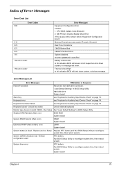
...BIOS will issue 4 short beeps then shut down system, no message will shut down system, not show . Replace and run Setup Replace RTC battery and Run BIOS Setup Utility to reconfigure system time, then reboot system. Keyboard Controller Failed see "Keyboard or Auxiliary Input Device Check" on page... Channel Master Drive Error (THe causes will be shown before "Equipment Configuration Error") Memory Error at offset: nnnn DIMM System board System battery is specified. Error Message List Error Messages FRU/Action in Sequence Failure Fixed Disk Reconnect hard disk drive connector.
...BIOS will issue 4 short beeps then shut down system, no message will shut down system, not show . Replace and run Setup Replace RTC battery and Run BIOS Setup Utility to reconfigure system time, then reboot system. Keyboard Controller Failed see "Keyboard or Auxiliary Input Device Check" on page... Channel Master Drive Error (THe causes will be shown before "Equipment Configuration Error") Memory Error at offset: nnnn DIMM System board System battery is specified. Error Message List Error Messages FRU/Action in Sequence Failure Fixed Disk Reconnect hard disk drive connector.
TravelMate 4100/4600 Service Guide
Page 86
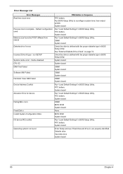
... DIMM System board Fail-Safe Timer NMI Failed DIMM System board Device Address Conflict Run "Load Default Settings" in BIOS Setup Utility. RTC battery System board Allocation Error for device Run "Load Default Settings" in BIOS Setup Utility. System board Previous boot incomplete - DIMM System board ... Data BIOS ROM System board I/O device IRQ conflict Run "Load Default Settings" in BIOS Setup Utility. Incorrect Drive A type - RTC battery System board Operating system not found by POST differed from CMOS Run "Load Default Settings" in Sequence Real time clock error RTC...
... DIMM System board Fail-Safe Timer NMI Failed DIMM System board Device Address Conflict Run "Load Default Settings" in BIOS Setup Utility. RTC battery System board Allocation Error for device Run "Load Default Settings" in BIOS Setup Utility. System board Previous boot incomplete - DIMM System board ... Data BIOS ROM System board I/O device IRQ conflict Run "Load Default Settings" in BIOS Setup Utility. Incorrect Drive A type - RTC battery System board Operating system not found by POST differed from CMOS Run "Load Default Settings" in Sequence Real time clock error RTC...

TravelMate 4100/4600 Service Guide
Page 87
... POST. LED board. See "Power System Check" on LCD during POST but system runs correctly. Ensure every connector is blank. Power source (battery pack and power adapter). Power source (battery pack and power adapter). Ensure every connector is connected tightly and correctly. See "Power System Check" on an external CRT. But you...
... POST. LED board. See "Power System Check" on LCD during POST but system runs correctly. Ensure every connector is blank. Power source (battery pack and power adapter). Power source (battery pack and power adapter). Ensure every connector is connected tightly and correctly. See "Power System Check" on an external CRT. But you...


