
XD1170D/1280D Service Guide
Page 8
... System Introduction 1 Technical Specification 1 Product Overview 2 Chapter 2 Firware Upgrade 7 Equipment Needed 7 Installation Procedure 8 USB Driver Upgrade Procedure 10 Firmware Upgrade Procedure 12 EDID Upgrade 15 Equipment Needed 15 Setup Procedure 16 EDID Key-in Procedure 16 ... 54 Exploded Overview 54 Appendix Serial Number Definition System 112 I. The Different Parts (PD100 / PD100D / PD120 / PD120D / XD1170D / XD1270D ) 114 IV. Serial Number System Definition 112 II. Identification Method for "D" Model 118 PCBA Code Definition 113 III.
... System Introduction 1 Technical Specification 1 Product Overview 2 Chapter 2 Firware Upgrade 7 Equipment Needed 7 Installation Procedure 8 USB Driver Upgrade Procedure 10 Firmware Upgrade Procedure 12 EDID Upgrade 15 Equipment Needed 15 Setup Procedure 16 EDID Key-in Procedure 16 ... 54 Exploded Overview 54 Appendix Serial Number Definition System 112 I. The Different Parts (PD100 / PD100D / PD120 / PD120D / XD1170D / XD1270D ) 114 IV. Serial Number System Definition 112 II. Identification Method for "D" Model 118 PCBA Code Definition 113 III.

XD1170D/1280D Service Guide
Page 18
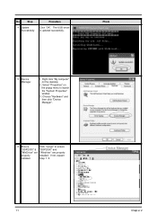
Chapter2 10 Plug in Power Cord. 3. The light will not function. continue Then, wait for about 1 minute. Hold on "Menu" button and then plug in USB Cable into the Projector. 2. Wait for about 5 seconds. (Note: The system fan will not function as well.) 2 Execute Program Execute the C:\Program files\DLP Composer\usbupdata.cmd. (Note: The "DLP Composer" program must be closed first.) Photo 3 Type any key to Press any key to continue. USB Driver Upgrade Procedure No Step 1 Set-up Procedure 1.
Chapter2 10 Plug in Power Cord. 3. The light will not function. continue Then, wait for about 1 minute. Hold on "Menu" button and then plug in USB Cable into the Projector. 2. Wait for about 5 seconds. (Note: The system fan will not function as well.) 2 Execute Program Execute the C:\Program files\DLP Composer\usbupdata.cmd. (Note: The "DLP Composer" program must be closed first.) Photo 3 Type any key to Press any key to continue. USB Driver Upgrade Procedure No Step 1 Set-up Procedure 1.
XD1170D/1280D Service Guide
Page 19
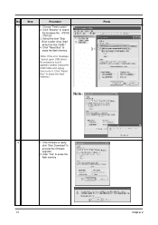
No Step 4 Update Successfully Procedure Click "OK". Right click "My computer" on the popup menu to ensure "DDP2000" & "DDP2000" and "WinDriver" are "Windriver" are properly properly installed. Choose "Hardware" and then click "Device Manager". 6 Ensure Click "Jungo" to launch the "System Properties" window. 3. If not, repeart installed Step 1~5. Photo 5 Device Manager 1. Device Manager 11 Chapt er 2 Select "Properties" on the desktop. 2. The USB driver is updated successfully.
No Step 4 Update Successfully Procedure Click "OK". Right click "My computer" on the popup menu to ensure "DDP2000" & "DDP2000" and "WinDriver" are "Windriver" are properly properly installed. Choose "Hardware" and then click "Device Manager". 6 Ensure Click "Jungo" to launch the "System Properties" window. 3. If not, repeart installed Step 1~5. Photo 5 Device Manager 1. Device Manager 11 Chapt er 2 Select "Properties" on the desktop. 2. The USB driver is updated successfully.
XD1170D/1280D Service Guide
Page 21
Click "Browse" to erase the flash memory. (Note: If the error message "cannot open USB driver No projectors found" appears, please unplug the USB Cable and replug, then re-do 4. Click "Reset Bus" to search the firmware file. (PD100 / PD120) 3. No ...
Click "Browse" to erase the flash memory. (Note: If the error message "cannot open USB driver No projectors found" appears, please unplug the USB Cable and replug, then re-do 4. Click "Reset Bus" to search the firmware file. (PD100 / PD120) 3. No ...
XD1170D/1280D Service Guide
Page 36
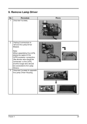
Note: When assembling the LVPS, please be aware of the LVPS connector connection. (the shorter wire should be connected to the LVPS, and the longer wire should be connected to the Lamp Driver.) 3 Unscrew 4 screws to remove the Lamp Driver Module. Remove Lamp Driver No Procedure 1 Unscrew 4 screws. Chapter 3 28 9. Photo 2 Unplug 2 connectors to separate the Lamp Driver Housing.
Note: When assembling the LVPS, please be aware of the LVPS connector connection. (the shorter wire should be connected to the LVPS, and the longer wire should be connected to the Lamp Driver.) 3 Unscrew 4 screws to remove the Lamp Driver Module. Remove Lamp Driver No Procedure 1 Unscrew 4 screws. Chapter 3 28 9. Photo 2 Unplug 2 connectors to separate the Lamp Driver Housing.
XD1170D/1280D Service Guide
Page 45
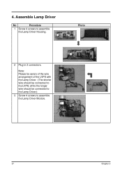
while the longer wire should be connected to the Lamp Driver.) 3 Screw 4 screws to assemble the Lamp Driver Module. 37 Chapter 3 Photo 2 Plug in 2 connectors. Assemble Lamp Driver No Procedure 1 Screw 4 screws to the LVPS; Note: Please be aware of the wire arrangement of the LVPS with the Lamp Driver. (The shorter wire should be connected to assemble the Lamp Driver Housing. 4.
while the longer wire should be connected to the Lamp Driver.) 3 Screw 4 screws to assemble the Lamp Driver Module. 37 Chapter 3 Photo 2 Plug in 2 connectors. Assemble Lamp Driver No Procedure 1 Screw 4 screws to the LVPS; Note: Please be aware of the wire arrangement of the LVPS with the Lamp Driver. (The shorter wire should be connected to assemble the Lamp Driver Housing. 4.
XD1170D/1280D Service Guide
Page 55
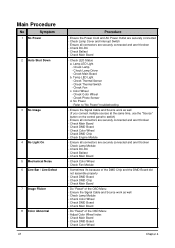
... and the DMD Board did not assemble properly - Ensure the Signal Cable and Source work as well - Check Main Board - Lamp LED Light - Check Lamp Driver - Check Main Board b. Color Wheel - Check Color Wheel Chapt er 4 Check Photo Sensor d. Check DMD Board - Check Engine Module - Check Ballast - Sometimes it's because of...
... and the DMD Board did not assemble properly - Ensure the Signal Cable and Source work as well - Check Main Board - Lamp LED Light - Check Lamp Driver - Check Main Board b. Color Wheel - Check Color Wheel Chapt er 4 Check Photo Sensor d. Check DMD Board - Check Engine Module - Check Ballast - Sometimes it's because of...

XD1170D/1280D Service Guide
Page 64
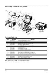
... UL1007 BLACK 80mm p3.0/p3.0 LT20 SCREW PAN MECH M3*5 Ni 13 85.1A626G050 SCREW PAN MECH M2.6*5 BLACK NYLOK 14 70.82G19G001 ASSY LAMP DRIVER MDULE EP7190 15 41.82G03G001 EMI GASKET USB CONNECTOR EP719 Note: Please refer to RSPL for updated Part Number. Chapt er 5 56 PD100 Assy Bottom...
... UL1007 BLACK 80mm p3.0/p3.0 LT20 SCREW PAN MECH M3*5 Ni 13 85.1A626G050 SCREW PAN MECH M2.6*5 BLACK NYLOK 14 70.82G19G001 ASSY LAMP DRIVER MDULE EP7190 15 41.82G03G001 EMI GASKET USB CONNECTOR EP719 Note: Please refer to RSPL for updated Part Number. Chapt er 5 56 PD100 Assy Bottom...
XD1170D/1280D Service Guide
Page 65
... UL1007 BLACK 80mm p3.0/p3.0 LT20 SCREW PAN MECH M3*5 Ni 13 85.1A626G050 SCREW PAN MECH M2.6*5 BLACK NYLOK 14 70.82G19G001 ASSY LAMP DRIVER MDULE EP7190 15 41.82G03G001 EMI GASKET USB CONNECTOR EP719 Note: Please refer to RSPL for updated Part Number. 57 Chapt er 5 PD120 Assy Bottom...
... UL1007 BLACK 80mm p3.0/p3.0 LT20 SCREW PAN MECH M3*5 Ni 13 85.1A626G050 SCREW PAN MECH M2.6*5 BLACK NYLOK 14 70.82G19G001 ASSY LAMP DRIVER MDULE EP7190 15 41.82G03G001 EMI GASKET USB CONNECTOR EP719 Note: Please refer to RSPL for updated Part Number. 57 Chapt er 5 PD120 Assy Bottom...
XD1170D/1280D Service Guide
Page 93
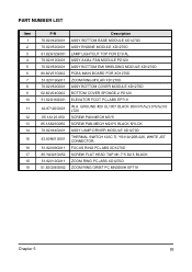
... MN3600H EP719 Chapt er 5 85 GROUND #20 UL1007 BLACK 80mm%%c3.0/%%c3.0 LT20 SCREW PAN MECH M3*5 SCREW PAN MECH M2.6*5 BLACK NYLOK ASSY LAMP DRIVER MODULE XD1270D THERMAL SWITCH 120C TI, YS11A120B-026, WHITE JST CONNECTOR. PART NUMBER LIST Item 1 2 3 4 5 6 7 8 9 10 11 12 13 14 15 16 17 18 19....1A123.050 85.1A626G050 70.82V44G001 43.80N01G001 51.82V09G011 85.YA321G052 51.82V10G011 51.82G08G002 Description ASSY BOTTOM BASE MODULE XD1270D ASSY ENGINE MODULE XD1170D LAMP LIGHTCUT TOP FOR E19 AL ASSY AXIAL FAN MODULE PD120 ASSY BOTTOM EMI SHIELDING MODULE XD1270D PCBA MAIN BOARD FOR...
... MN3600H EP719 Chapt er 5 85 GROUND #20 UL1007 BLACK 80mm%%c3.0/%%c3.0 LT20 SCREW PAN MECH M3*5 SCREW PAN MECH M2.6*5 BLACK NYLOK ASSY LAMP DRIVER MODULE XD1270D THERMAL SWITCH 120C TI, YS11A120B-026, WHITE JST CONNECTOR. PART NUMBER LIST Item 1 2 3 4 5 6 7 8 9 10 11 12 13 14 15 16 17 18 19....1A123.050 85.1A626G050 70.82V44G001 43.80N01G001 51.82V09G011 85.YA321G052 51.82V10G011 51.82G08G002 Description ASSY BOTTOM BASE MODULE XD1270D ASSY ENGINE MODULE XD1170D LAMP LIGHTCUT TOP FOR E19 AL ASSY AXIAL FAN MODULE PD120 ASSY BOTTOM EMI SHIELDING MODULE XD1270D PCBA MAIN BOARD FOR...
XD1170D/1280D Service Guide
Page 102
...%%c3.0/%%c3.0 LT20 12 85.1A123.050 SCREW PAN MECH M3*5 13 85.1A626G050 SCREW PAN MECH M2.6*5 BLACK NYLOK 14 70.82V44G001 ASSY LAMP DRIVER MODULE XD1270D 15 43.80N01G001 THERMAL SWITCH 120C TI, YS11A120B-026, WHITE JST CONNECTOR. 16 51.82V09G011 FOCUS RING PC+ABS XD1270D 17 85.YA321G052...
...%%c3.0/%%c3.0 LT20 12 85.1A123.050 SCREW PAN MECH M3*5 13 85.1A626G050 SCREW PAN MECH M2.6*5 BLACK NYLOK 14 70.82V44G001 ASSY LAMP DRIVER MODULE XD1270D 15 43.80N01G001 THERMAL SWITCH 120C TI, YS11A120B-026, WHITE JST CONNECTOR. 16 51.82V09G011 FOCUS RING PC+ABS XD1270D 17 85.YA321G052...
XD1170D/1280D Service Guide
Page 105
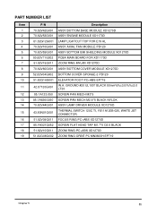
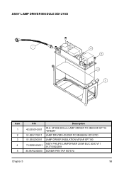
ASSY LAMP DRIVER MODULE XD1270D Item 1 2 3 4 5 P/N 42.82G01G001 51.82G17G011 51.82G23G001 75.85W04G001 85.WA123G060 Description W.A. 5P #28 200mm LAMP DRIVER TO MAIN BD EP719 "GREEN" LAMP DRIVER HOLDER PC MN3600H XD1270D LAMP DRIVER INSULATION MYLAR EP7190 ASSY PHILIPS LAMPDRIVER 200W EUC 200D/V11 913700822269 SCREW PAN TAP M3*6 Ni Chapter 5 96
ASSY LAMP DRIVER MODULE XD1270D Item 1 2 3 4 5 P/N 42.82G01G001 51.82G17G011 51.82G23G001 75.85W04G001 85.WA123G060 Description W.A. 5P #28 200mm LAMP DRIVER TO MAIN BD EP719 "GREEN" LAMP DRIVER HOLDER PC MN3600H XD1270D LAMP DRIVER INSULATION MYLAR EP7190 ASSY PHILIPS LAMPDRIVER 200W EUC 200D/V11 913700822269 SCREW PAN TAP M3*6 Ni Chapter 5 96


