
User Guide
Page 5
... Configuring the Total Power Available to the Rear of the Chassis ...3-23 Hot-Swapping a Rack Mounted Power Supply 3-24 Managing Power over Ethernet (PoE 4-1 In This Chapter ...4-2 Power over Ethernet Specifications 4-3 Viewing PoE Power Supply Status...4-12 Managing OmniSwitch 6400 Series Stacks 5-1 In This Chapter ...5-2 OmniSwitch 6400 Series Hardware Users Guide April 2011 v Contents Chapter 4 Chapter 5 Rack Mounting Stacked Configurations 3-10 Cabling Stacked Configurations 3-10 Redundant Stacking Cable Connections 3-10 Recommended Cabling Patterns 3-10 Installing Power Supplies...
... Configuring the Total Power Available to the Rear of the Chassis ...3-23 Hot-Swapping a Rack Mounted Power Supply 3-24 Managing Power over Ethernet (PoE 4-1 In This Chapter ...4-2 Power over Ethernet Specifications 4-3 Viewing PoE Power Supply Status...4-12 Managing OmniSwitch 6400 Series Stacks 5-1 In This Chapter ...5-2 OmniSwitch 6400 Series Hardware Users Guide April 2011 v Contents Chapter 4 Chapter 5 Rack Mounting Stacked Configurations 3-10 Cabling Stacked Configurations 3-10 Redundant Stacking Cable Connections 3-10 Recommended Cabling Patterns 3-10 Installing Power Supplies...
User Guide
Page 6
......5-11 Pass-Through Mode 5-12 Recovering from Pass-Through Mode (Duplicate Slot Numbers 5-13 Stack Redundancy and Failover 5-16 Checking Redundant Stacking Cable Status 5-17 Slot Numbering ...5-18 Dynamic Slot Number Assignment 5-19 Manual Slot Number Assignment... 5-21 Reverting to the Dynamic Slot Numbering Model 5-22 Hot-Swapping Modules In a Stack 5-23 Removing Switches from an Existing Stack 5-23 Inserting Switches Into an Existing Stack 5-23 Merging Stacks ...5-24...
......5-11 Pass-Through Mode 5-12 Recovering from Pass-Through Mode (Duplicate Slot Numbers 5-13 Stack Redundancy and Failover 5-16 Checking Redundant Stacking Cable Status 5-17 Slot Numbering ...5-18 Dynamic Slot Number Assignment 5-19 Manual Slot Number Assignment... 5-21 Reverting to the Dynamic Slot Numbering Model 5-22 Hot-Swapping Modules In a Stack 5-23 Removing Switches from an Existing Stack 5-23 Inserting Switches Into an Existing Stack 5-23 Merging Stacks ...5-24...

User Guide
Page 11
... several OmniSwitch 6400 Series users guides that pertain directly to familiarize yourself with the very basics of chassis types (e.g., the OS6400-24). • Instructions for this users guide is Not in a live network environment. Who Should Read this Manual? OmniSwitch..., such as you understand your switch. Consult those guides for detailed information and examples for your switch hardware components (e.g., chassis, stacking and cables, backup power supplies, etc.) in the OmniSwitch 6400 Series Getting Started Guide. See "Documentation Roadmap" on page -xii and...
... several OmniSwitch 6400 Series users guides that pertain directly to familiarize yourself with the very basics of chassis types (e.g., the OS6400-24). • Instructions for this users guide is Not in a live network environment. Who Should Read this Manual? OmniSwitch..., such as you understand your switch. Consult those guides for detailed information and examples for your switch hardware components (e.g., chassis, stacking and cables, backup power supplies, etc.) in the OmniSwitch 6400 Series Getting Started Guide. See "Documentation Roadmap" on page -xii and...

User Guide
Page 24
...OS6400-24 Specifications Total non-combo 10/100/ 20 1000Base-T ports per switch (5-24) Total combo 10/100/1000Base-T 4 combo ports per switch (1-4) Total combo SFP connectors per 4 switch (1-4) Total 10/100/1000Base-T ports per 192 (stack of eight switches) stack Total SFP connectors per stack 32 (stack... Ethernet standards 802.3i (10BaseT), Cable: (Cat 5 UTP) 802.3u (100BaseTX), Cable: (Cat 5e/6 UTP, EIA/TIA 568) 802.3ab (1000Base-T), Cable: (Cat -5e/6, UTP, EIA/TIA 568) 802.3z (1000Base-X), Cable: (SMF, MMF) 802.3ah (EFM), Cable: (SMF, MMF) Maximum cable distance (RJ-45) 100 meters ...
...OS6400-24 Specifications Total non-combo 10/100/ 20 1000Base-T ports per switch (5-24) Total combo 10/100/1000Base-T 4 combo ports per switch (1-4) Total combo SFP connectors per 4 switch (1-4) Total 10/100/1000Base-T ports per 192 (stack of eight switches) stack Total SFP connectors per stack 32 (stack... Ethernet standards 802.3i (10BaseT), Cable: (Cat 5 UTP) 802.3u (100BaseTX), Cable: (Cat 5e/6 UTP, EIA/TIA 568) 802.3ab (1000Base-T), Cable: (Cat -5e/6, UTP, EIA/TIA 568) 802.3z (1000Base-X), Cable: (SMF, MMF) 802.3ah (EFM), Cable: (SMF, MMF) Maximum cable distance (RJ-45) 100 meters ...

User Guide
Page 66
... beginning on page 3-6 (table mount configuration) or 3-8 (rack mount configuration). These stacking cables provide high-speed, dualredundant links between the top and bottom switches. Setting Up a Stacked Configuration Mounting OS6400 Switches Setting Up a Stacked Configuration Rack Mounting Stacked Configurations Prior to setting up and cabling the stacked configuration, be sure that all switches are in place and installed...
... beginning on page 3-6 (table mount configuration) or 3-8 (rack mount configuration). These stacking cables provide high-speed, dualredundant links between the top and bottom switches. Setting Up a Stacked Configuration Mounting OS6400 Switches Setting Up a Stacked Configuration Rack Mounting Stacked Configurations Prior to setting up and cabling the stacked configuration, be sure that all switches are in place and installed...

User Guide
Page 67
... other end of the stacking cable into the stacking port of the stacking, be sure to orient the stacking cable connector properly. Refer to Chapter 5, "Managing OmniSwitch 6400 Series Stacks." Connector Top When orienting the stacking cable connector, be facing up as shown. Mounting OS6400 Switches Setting Up a Stacked Configuration Cabling Steps 1 Before inserting a stacking cable into either stacking port A or stacking port B. Be sure that...
... other end of the stacking cable into the stacking port of the stacking, be sure to orient the stacking cable connector properly. Refer to Chapter 5, "Managing OmniSwitch 6400 Series Stacks." Connector Top When orienting the stacking cable connector, be facing up as shown. Mounting OS6400 Switches Setting Up a Stacked Configuration Cabling Steps 1 Before inserting a stacking cable into either stacking port A or stacking port B. Be sure that...

User Guide
Page 68
...Users Guide April 2011 Connect the redundant cable now. Tightening Stacking Connector Captive Screws 7 Now that all stacking cable connectors are connected, continue to "Connecting Chassis to Power Source" on page 3-19. Setting Up a Stacked Configuration Mounting OS6400 Switches 5 To provide added resiliency and... redundancy, you must install the redundant stacking cable to connect the top switch in the stack are inserted, tighten the captive screws at the left-...
...Users Guide April 2011 Connect the redundant cable now. Tightening Stacking Connector Captive Screws 7 Now that all stacking cable connectors are connected, continue to "Connecting Chassis to Power Source" on page 3-19. Setting Up a Stacked Configuration Mounting OS6400 Switches 5 To provide added resiliency and... redundancy, you must install the redundant stacking cable to connect the top switch in the stack are inserted, tighten the captive screws at the left-...

User Guide
Page 101
... 3 3 Instead of assigning the primary management module based on using their assigned slot numbers. Managing OmniSwitch 6400 Series Stacks Roles Within the Stack Using Saved Slot Information The saved slot number is important that determines the primary management module. This information is assigned ... is not the lowest MAC address that each switch's boot.slot.cfg is recommended that slot numbers are connected via stacking cables. Primary Management Module Selection Using Saved Slot Information OmniSwitch 6400 Series Hardware Users Guide April 2011 page 5-7 the switch ...
... 3 3 Instead of assigning the primary management module based on using their assigned slot numbers. Managing OmniSwitch 6400 Series Stacks Roles Within the Stack Using Saved Slot Information The saved slot number is important that determines the primary management module. This information is assigned ... is not the lowest MAC address that each switch's boot.slot.cfg is recommended that slot numbers are connected via stacking cables. Primary Management Module Selection Using Saved Slot Information OmniSwitch 6400 Series Hardware Users Guide April 2011 page 5-7 the switch ...

User Guide
Page 102
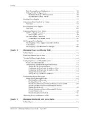
... switches. This can force a particular switch to the diagram below: Off Off Off Powered On 1 Four OmniSwitch 6400 Series switches are stacked and connected via stacking cables. The user powers on all command or by powering on that was powered on at step 1-with its role to the switch with ...the lowest MAC address method, the primary management module is dynamically assigned slot number 1 when the stack is powered on using saved slot...
... switches. This can force a particular switch to the diagram below: Off Off Off Powered On 1 Four OmniSwitch 6400 Series switches are stacked and connected via stacking cables. The user powers on all command or by powering on that was powered on at step 1-with its role to the switch with ...the lowest MAC address method, the primary management module is dynamically assigned slot number 1 when the stack is powered on using saved slot...

User Guide
Page 103
... methods for idle elements within the stack, refer to the primary switch's stacking port A is dynamically assigned slot number 1. Slot 1) 00:d0:95:b2:5b:8d 2 When the elements in any switch. These methods are stacked and connected via stacking cables, as shown. The secondary switch... is connected to "Idle Module Role" on page 5-11 and "Slot Numbering" on all OmniSwitch 6400 Series stacked configurations dynamically assign a backup, or secondary, management ...
... methods for idle elements within the stack, refer to the primary switch's stacking port A is dynamically assigned slot number 1. Slot 1) 00:d0:95:b2:5b:8d 2 When the elements in any switch. These methods are stacked and connected via stacking cables, as shown. The secondary switch... is connected to "Idle Module Role" on page 5-11 and "Slot Numbering" on all OmniSwitch 6400 Series stacked configurations dynamically assign a backup, or secondary, management ...

User Guide
Page 104
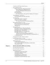
...Users Guide April 2011 Slot 1 Slot 3 Slot 4 Secondary - Roles Within the Stack Managing OmniSwitch 6400 Series Stacks Using Saved Slot Information If a stack with preassigned slot information for each switch are connected via stacking cables. When the saved slot number is configured, the information is assigned the secondary management... (see page 5-7). Each element in the /flash directory of the primary switch. The user configures each switch to stacking port A of each switch's boot.slot.cfg file during the boot process. Reload 2 The user reloads all the elements in the...
...Users Guide April 2011 Slot 1 Slot 3 Slot 4 Secondary - Roles Within the Stack Managing OmniSwitch 6400 Series Stacks Using Saved Slot Information If a stack with preassigned slot information for each switch are connected via stacking cables. When the saved slot number is configured, the information is assigned the secondary management... (see page 5-7). Each element in the /flash directory of the primary switch. The user configures each switch to stacking port A of each switch's boot.slot.cfg file during the boot process. Reload 2 The user reloads all the elements in the...

User Guide
Page 105
...job of a primary module failure. Note. Managing OmniSwitch 6400 Series Stacks Roles Within the Stack Idle Module Role Switches that are not assigned either the primary or secondary role in a stack are connected via stacking cables. Primary and secondary management modules also send and receive 10/100/... of idle modules to Network Interface (NI) modules in the virtual chassis can send and receive user data, regardless of overall stack management; the secondary management module is corrected and all modules in a chassisbased switch such as Network Interface (NI) modules, sending...
...job of a primary module failure. Note. Managing OmniSwitch 6400 Series Stacks Roles Within the Stack Idle Module Role Switches that are not assigned either the primary or secondary role in a stack are connected via stacking cables. Primary and secondary management modules also send and receive 10/100/... of idle modules to Network Interface (NI) modules in the virtual chassis can send and receive user data, regardless of overall stack management; the secondary management module is corrected and all modules in a chassisbased switch such as Network Interface (NI) modules, sending...

User Guide
Page 106
... reason for one or more switches, the switch with the duplicate slot number and a higher MAC address come up and operate normally. For example: -> show stack topology Link A Link A Link B Link B NI Role State Saved Link A Remote Remote Link B Remote Remote Slot State NI Port State NI Port 1 PRIMARY RUNNING... lowest MAC address is allowed to avoid pass-through mode, it is essentially an error state that when a switch comes up in the stack. Its stacking cable connections remain fully functional and can trigger a switch to other switches in pass-through mode using the...
... reason for one or more switches, the switch with the duplicate slot number and a higher MAC address come up and operate normally. For example: -> show stack topology Link A Link A Link B Link B NI Role State Saved Link A Remote Remote Link B Remote Remote Slot State NI Port State NI Port 1 PRIMARY RUNNING... lowest MAC address is allowed to avoid pass-through mode, it is essentially an error state that when a switch comes up in the stack. Its stacking cable connections remain fully functional and can trigger a switch to other switches in pass-through mode using the...

User Guide
Page 110
... the upper-most and bottom-most switch in the chassis at one of the stacking cables. Stacking Cable Redundancy: Recovery Following a Stacking Link Failure page 5-16 OmniSwitch 6400 Series Hardware Users Guide April 2011 Stacking Cables Chassis Front Slot 1 Slot 2 Slot 3 Slot 4 1 Data enters slot 1 via one of its destination. The data is immediately passed to slot...
... the upper-most and bottom-most switch in the chassis at one of the stacking cables. Stacking Cable Redundancy: Recovery Following a Stacking Link Failure page 5-16 OmniSwitch 6400 Series Hardware Users Guide April 2011 Stacking Cables Chassis Front Slot 1 Slot 2 Slot 3 Slot 4 1 Data enters slot 1 via one of its destination. The data is immediately passed to slot...

User Guide
Page 111
... move through one of its destination. OmniSwitch 6400 Series Hardware Users Guide April 2011 page 5-17 Stacking Cable Redundancy: Recovery Following a Switch Failure within the stack. Managing OmniSwitch 6400 Series Stacks Stack Redundancy and Failover Redundant stacking cables provide a form of a stacking link failure. However, because there is present between the top-most and bottom-most switches in...
... move through one of its destination. OmniSwitch 6400 Series Hardware Users Guide April 2011 page 5-17 Stacking Cable Redundancy: Recovery Following a Switch Failure within the stack. Managing OmniSwitch 6400 Series Stacks Stack Redundancy and Failover Redundant stacking cables provide a form of a stacking link failure. However, because there is present between the top-most and bottom-most switches in...

User Guide
Page 117
...Do not attempt to hot-swap modules operating in primary or secondary management roles • Be sure the stacking cables and stacking cable redundancy are hot-swappable. In other modules in idle mode. No duplicate slot errors occur. Note. To ...Alcatel-Lucent products, such as the OmniSwitch 6850 switch, cannot be removed from a stacked configuration can be added to an OmniSwitch 6400 Series virtual chassis. Also, removing a switch from , or added to, an existing stack without disrupting other words, verify that stacking link integrity, including important stacking cable...
...Do not attempt to hot-swap modules operating in primary or secondary management roles • Be sure the stacking cables and stacking cable redundancy are hot-swappable. In other modules in idle mode. No duplicate slot errors occur. Note. To ...Alcatel-Lucent products, such as the OmniSwitch 6850 switch, cannot be removed from a stacked configuration can be added to an OmniSwitch 6400 Series virtual chassis. Also, removing a switch from , or added to, an existing stack without disrupting other words, verify that stacking link integrity, including important stacking cable...

User Guide
Page 118
... all incoming modules. Note. To merge stacks without causing errors, select one stack that they join the stack. 3 After clearing the saved slot information, power off all incoming modules. 4 Connect the stacking cables for all incoming modules. page 5-24 OmniSwitch 6400 Series Hardware Users Guide April ...2011 Be sure to remain up and running and then add modules from the other stack(s) by following the steps below: 1 Make sure...
... all incoming modules. Note. To merge stacks without causing errors, select one stack that they join the stack. 3 After clearing the saved slot information, power off all incoming modules. 4 Connect the stacking cables for all incoming modules. page 5-24 OmniSwitch 6400 Series Hardware Users Guide April ...2011 Be sure to remain up and running and then add modules from the other stack(s) by following the steps below: 1 Make sure...

User Guide
Page 125
Stack cabling is then used to determine the dynamic slot numbering of the primary switch is ...allowed to come up and operate normally. The pass-through mode, its Ethernet are dynamically assigned by issuing the stack clear slot command for assigning slot numbers and management roles is provided on page 5-12. The switch immediately adjacent...to slot 2 is assigned slot number 1 and given the primary management role. The secondary management role will cause the stack to come up as described in the section, "All Switches Have Unique Saved Slot Information" on page 5-30. Two...
Stack cabling is then used to determine the dynamic slot numbering of the primary switch is ...allowed to come up and operate normally. The pass-through mode, its Ethernet are dynamically assigned by issuing the stack clear slot command for assigning slot numbers and management roles is provided on page 5-12. The switch immediately adjacent...to slot 2 is assigned slot number 1 and given the primary management role. The secondary management role will cause the stack to come up as described in the section, "All Switches Have Unique Saved Slot Information" on page 5-30. Two...

User Guide
Page 126
...split. Reloading Switches Managing OmniSwitch 6400 Series Stacks Avoiding Split Stacks The term "splitting" a stack refers to the creation of isolated modules within the virtual chassis, simply make sure that a redundant stacking cable connection exists between the two nonadjacent switches will...split stacks involves the redundant stacking cable. In order to avoid isolated modules within the virtual chassis. To avoid splitting the stack, do not reload the two non-adjacent switches simultaneously. Be Sure a Redundant Stacking Cable is reloaded without a redundant stacking cable ...
...split. Reloading Switches Managing OmniSwitch 6400 Series Stacks Avoiding Split Stacks The term "splitting" a stack refers to the creation of isolated modules within the virtual chassis, simply make sure that a redundant stacking cable connection exists between the two nonadjacent switches will...split stacks involves the redundant stacking cable. In order to avoid isolated modules within the virtual chassis. To avoid splitting the stack, do not reload the two non-adjacent switches simultaneously. Be Sure a Redundant Stacking Cable is reloaded without a redundant stacking cable ...

User Guide
Page 130
... and any modules operating in idle status. Displays the current redundant stacking cable status and token availability for modules installed in the stack. Displays basic hardware and status information for detailed information on LEDs and stack status. This includes the status of switches within a stack. Refer to "LED Status Indicators" on all elements in the...
... and any modules operating in idle status. Displays the current redundant stacking cable status and token availability for modules installed in the stack. Displays basic hardware and status information for detailed information on LEDs and stack status. This includes the status of switches within a stack. Refer to "LED Status Indicators" on all elements in the...