
Hardware User Guide
Page 4
... Port - RJ-45 Pinout 2-32 10/100/1000 Mbps Power over Ethernet Port - Connector Pinout 2-33 Mounting OS6400 Switches 3-1 General Mounting Recommendations 3-1 Recommended Clearances 3-1 Elevated Operating Ambient Temperatures 3-2 Reduced Air Flow ...3-2 Mechanical Loading ... 3-8 Rack Mount Guidelines 3-8 Rack Mounting Steps 3-8 Next Steps ...3-9 Setting Up a Stacked Configuration 3-10 Rack Mounting Stacked Configurations 3-10 Cabling Stacked Configurations 3-10 Redundant Stacking Cable Connections 3-10 OmniSwitch 6400 Series Hardware Users Guide July 2010 RJ-45 Pinout (non-...
... Port - RJ-45 Pinout 2-32 10/100/1000 Mbps Power over Ethernet Port - Connector Pinout 2-33 Mounting OS6400 Switches 3-1 General Mounting Recommendations 3-1 Recommended Clearances 3-1 Elevated Operating Ambient Temperatures 3-2 Reduced Air Flow ...3-2 Mechanical Loading ... 3-8 Rack Mount Guidelines 3-8 Rack Mounting Steps 3-8 Next Steps ...3-9 Setting Up a Stacked Configuration 3-10 Rack Mounting Stacked Configurations 3-10 Cabling Stacked Configurations 3-10 Redundant Stacking Cable Connections 3-10 OmniSwitch 6400 Series Hardware Users Guide July 2010 RJ-45 Pinout (non-...
Hardware User Guide
Page 5
... Guide July 2010 v Same Priority Level on All PD 5-10 Priority Disconnect is Enabled; Contents Chapter 4 Chapter 5 Recommended Cabling Patterns 3-10 Installing Power Supplies 3-13 Connecting a Power Supply to the Chassis 3-13 Next Steps ...3-14 Rack Mounting Power ...Chassis 3-23 Hot-Swapping a Rack Mounted Power Supply 3-24 Booting OmniSwitch 6400 Series Switches 4-1 Booting a Stand-Alone Switch 4-1 Booting Stacked Configurations 4-2 Monitoring the Chassis 4-3 Checking the Overall Chassis Status 4-3 Checking the Temperature Status 4-3 Checking the Fan Status 4-4 Checking the...
... Guide July 2010 v Same Priority Level on All PD 5-10 Priority Disconnect is Enabled; Contents Chapter 4 Chapter 5 Recommended Cabling Patterns 3-10 Installing Power Supplies 3-13 Connecting a Power Supply to the Chassis 3-13 Next Steps ...3-14 Rack Mounting Power ...Chassis 3-23 Hot-Swapping a Rack Mounted Power Supply 3-24 Booting OmniSwitch 6400 Series Switches 4-1 Booting a Stand-Alone Switch 4-1 Booting Stacked Configurations 4-2 Monitoring the Chassis 4-3 Checking the Overall Chassis Status 4-3 Checking the Temperature Status 4-3 Checking the Fan Status 4-4 Checking the...
Hardware User Guide
Page 6
... Selection 6-6 Secondary Management Module Selection 6-9 Idle Module Role ...6-11 Pass-Through Mode 6-12 Recovering from Pass-Through Mode (Duplicate Slot Numbers 6-13 Stack Redundancy and Failover 6-16 Checking Redundant Stacking Cable Status 6-17 Slot Numbering ...6-18 Dynamic Slot Number Assignment 6-19 Manual Slot Number Assignment 6-21 Reverting to the Dynamic Slot Numbering Model...
... Selection 6-6 Secondary Management Module Selection 6-9 Idle Module Role ...6-11 Pass-Through Mode 6-12 Recovering from Pass-Through Mode (Duplicate Slot Numbers 6-13 Stack Redundancy and Failover 6-16 Checking Redundant Stacking Cable Status 6-17 Slot Numbering ...6-18 Dynamic Slot Number Assignment 6-19 Manual Slot Number Assignment 6-21 Reverting to the Dynamic Slot Numbering Model...

Hardware User Guide
Page 11
... information and examples for configuring your switch. You should already be familiar with your switch hardware components (e.g., chassis, stacking and cables, backup power supplies, etc.) in a live network environment. This manual will benefit from the material in this ... • Descriptions of switch configurations. • Descriptions of "availability" features. • Descriptions of chassis types (e.g., the OS6400-24). • Instructions for further information on switch hardware. The descriptive and procedural information in the OmniSwitch 6400 Series Getting ...
... information and examples for configuring your switch. You should already be familiar with your switch hardware components (e.g., chassis, stacking and cables, backup power supplies, etc.) in a live network environment. This manual will benefit from the material in this ... • Descriptions of switch configurations. • Descriptions of "availability" features. • Descriptions of chassis types (e.g., the OS6400-24). • Instructions for further information on switch hardware. The descriptive and procedural information in the OmniSwitch 6400 Series Getting ...

Hardware User Guide
Page 66
... all switches in a crossed (stacking port A to stacking port B) configuration. This provides effective failover in a stack are connected to each other by stacking cables. Setting Up a Stacked Configuration Mounting OS6400 Switches Setting Up a Stacked Configuration Rack Mounting Stacked Configurations Prior to setting up and cabling the stacked configuration, be sure that all switches are in a stack. For a stack to the instructions beginning on...
... all switches in a crossed (stacking port A to stacking port B) configuration. This provides effective failover in a stack are connected to each other by stacking cables. Setting Up a Stacked Configuration Mounting OS6400 Switches Setting Up a Stacked Configuration Rack Mounting Stacked Configurations Prior to setting up and cabling the stacked configuration, be sure that all switches are in a stack. For a stack to the instructions beginning on...
Hardware User Guide
Page 67
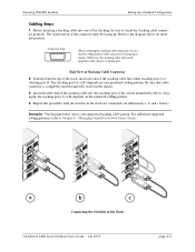
.... Reminder. The wide portion of the connector must be sure that cable connector is facing up . For additional supported cabling patterns, refer to the diagram below . Mounting OS6400 Switches Setting Up a Stacked Configuration Cabling Steps 1 Before inserting a stacking cable into one end of the stacking cable into the stacking port of the switch immediately below for more information. Otherwise, the...
.... Reminder. The wide portion of the connector must be sure that cable connector is facing up . For additional supported cabling patterns, refer to the diagram below . Mounting OS6400 Switches Setting Up a Stacked Configuration Cabling Steps 1 Before inserting a stacking cable into one end of the stacking cable into the stacking port of the switch immediately below for more information. Otherwise, the...

Hardware User Guide
Page 68
..., continue to "Connecting Chassis to Power Source" on page 3-19. Connect the redundant cable now. Setting Up a Stacked Configuration Mounting OS6400 Switches 5 To provide added resiliency and redundancy, you must install the redundant stacking cable to connect the top switch in the stack are inserted, tighten the captive screws at the left- Refer to the diagram...
..., continue to "Connecting Chassis to Power Source" on page 3-19. Connect the redundant cable now. Setting Up a Stacked Configuration Mounting OS6400 Switches 5 To provide added resiliency and redundancy, you must install the redundant stacking cable to connect the top switch in the stack are inserted, tighten the captive screws at the left- Refer to the diagram...

Hardware User Guide
Page 105
... the diagram below: Saved Slot 6 Saved Slot 5 Saved Slot 4 Saved Slot 3 1 Four OmniSwitch 6400 Series switches are connected via stacking cables. For more information on the lowest MAC address, the system software reads the slot information from this case, the switch assigned slot 3 ...has the lowest slot number in a stack, refer to have slot assignments 3, 4, 5, and 6. Reload 2 The user reloads all switches. Assumes Slot 6 Assumes Slot 5 Assumes Slot 4 Assumes ...
... the diagram below: Saved Slot 6 Saved Slot 5 Saved Slot 4 Saved Slot 3 1 Four OmniSwitch 6400 Series switches are connected via stacking cables. For more information on the lowest MAC address, the system software reads the slot information from this case, the switch assigned slot 3 ...has the lowest slot number in a stack, refer to have slot assignments 3, 4, 5, and 6. Reload 2 The user reloads all switches. Assumes Slot 6 Assumes Slot 5 Assumes Slot 4 Assumes ...

Hardware User Guide
Page 106
... switch powered on using saved slot information to determine the primary switch in its primary management role. The joining switches are essentially ineligible for determining a stack's primary management module. Because no other switches. For more information on at step 1. This is booted. Primary Management Module Selection Using Switch Uptime page 6-8 OmniSwitch... 6400 Series Hardware Users Guide July 2010 This can override both the MAC address and saved slot methods for primary status because they are stacked and connected via stacking cables.
... switch powered on using saved slot information to determine the primary switch in its primary management role. The joining switches are essentially ineligible for determining a stack's primary management module. Because no other switches. For more information on at step 1. This is booted. Primary Management Module Selection Using Switch Uptime page 6-8 OmniSwitch... 6400 Series Hardware Users Guide July 2010 This can override both the MAC address and saved slot methods for primary status because they are stacked and connected via stacking cables.

Hardware User Guide
Page 107
... slot numbering for selecting the secondary switch. Secondary Management Module Selection Using the Stacking Connection to the primary's stacking port A is automatically assigned the secondary management role. The secondary switch is no ...connected to "Idle Module Role" on page 6-11 and "Slot Numbering" on all OmniSwitch 6400 Series stacked configurations dynamically assign a backup, or secondary, management module during the boot process. None of the ... connected to the Primary Switch Note. These methods are stacked and connected via stacking cables, as shown.
... slot numbering for selecting the secondary switch. Secondary Management Module Selection Using the Stacking Connection to the primary's stacking port A is automatically assigned the secondary management role. The secondary switch is no ...connected to "Idle Module Role" on page 6-11 and "Slot Numbering" on all OmniSwitch 6400 Series stacked configurations dynamically assign a backup, or secondary, management module during the boot process. None of the ... connected to the Primary Switch Note. These methods are stacked and connected via stacking cables, as shown.

Hardware User Guide
Page 108
...to the boot.slot.cfg file located in the /flash directory of each switch. all switches. Reload 2 The user reloads all the elements in a stack should always be forced into pass-through mode, refer to page 6-12. Slot 1 Slot 3 Slot 4 Secondary - Slot 2 4 The switch with... more switches will be assigned a unique slot number. Otherwise, one or more information on all switches are connected via stacking cables. The switches in the stack and becomes the secondary management module. The switch with the second lowest assigned slot number becomes the secondary management role, ...
...to the boot.slot.cfg file located in the /flash directory of each switch. all switches. Reload 2 The user reloads all the elements in a stack should always be forced into pass-through mode, refer to page 6-12. Slot 1 Slot 3 Slot 4 Secondary - Slot 2 4 The switch with... more switches will be assigned a unique slot number. Otherwise, one or more information on all switches are connected via stacking cables. The switches in the stack and becomes the secondary management module. The switch with the second lowest assigned slot number becomes the secondary management role, ...

Hardware User Guide
Page 109
...like an NI with the next lowest slot number in a stack goes down for any of their . Note. Primary Secondary Idle Idle Primary Secondary 2 The primary and secondary management modules are connected via stacking cables. The stack is the job of idle modules to Network Interface (NI...) modules in the stack the idle module role. In other words, if the primary module in the stack will assume the secondary-or backup-management role....
...like an NI with the next lowest slot number in a stack goes down for any of their . Note. Primary Secondary Idle Idle Primary Secondary 2 The primary and secondary management modules are connected via stacking cables. The stack is the job of idle modules to Network Interface (NI...) modules in the stack the idle module role. In other words, if the primary module in the stack will assume the secondary-or backup-management role....

Hardware User Guide
Page 110
Its stacking cable connections remain fully functional and can trigger a switch to enter pass-through is essentially an error state that should not be forced into the pass-through mode. Slot number assignments are brought down (i.e, they cannot pass traffic). In this stack is rebooted, a duplicate ... switch comes up in pass-through mode, it is discovered on all elements in hardware monitoring commands such as show chassis, show ni, show stack topology Link A Link A Link B Link B NI Role State Saved Link A Remote Remote Link B Remote Remote Slot State NI Port State ...
Its stacking cable connections remain fully functional and can trigger a switch to enter pass-through is essentially an error state that should not be forced into the pass-through mode. Slot number assignments are brought down (i.e, they cannot pass traffic). In this stack is rebooted, a duplicate ... switch comes up in pass-through mode, it is discovered on all elements in hardware monitoring commands such as show chassis, show ni, show stack topology Link A Link A Link B Link B NI Role State Saved Link A Remote Remote Link B Remote Remote Slot State NI Port State ...

Hardware User Guide
Page 114
... enters slot 1 via one of a connection failure at all times. Stack Redundancy and Failover Managing OmniSwitch 6400 Series Stacks Stack Redundancy and Failover Important. For a stacked configuration to flow throughout the stack, even in the stack ensures that data will continue to have effective redundancy, a redundant stacking cable must be installed between slot 1 and slot 4), data is passed...
... enters slot 1 via one of a connection failure at all times. Stack Redundancy and Failover Managing OmniSwitch 6400 Series Stacks Stack Redundancy and Failover Important. For a stacked configuration to flow throughout the stack, even in the stack ensures that data will continue to have effective redundancy, a redundant stacking cable must be installed between slot 1 and slot 4), data is passed...

Hardware User Guide
Page 115
... 3 through one of dual redundancy. OmniSwitch 6400 Series Hardware Users Guide July 2010 page 6-17 Stacking Cable Redundancy: Recovery Following a Switch Failure within the stack. For example: -> show stack status command. Managing OmniSwitch 6400 Series Stacks Stack Redundancy and Failover Redundant stacking cables provide a form of its destination. Data can no longer move through a 10/100/1000 Ethernet...
... 3 through one of dual redundancy. OmniSwitch 6400 Series Hardware Users Guide July 2010 page 6-17 Stacking Cable Redundancy: Recovery Following a Switch Failure within the stack. For example: -> show stack status command. Managing OmniSwitch 6400 Series Stacks Stack Redundancy and Failover Redundant stacking cables provide a form of its destination. Data can no longer move through a 10/100/1000 Ethernet...

Hardware User Guide
Page 121
.... When removing a module, be sure that stacking link integrity, including important stacking cable redundancy, is no boot.slot.cfg file present in the stack. Other stackable Alcatel-Lucent products, such as a primary or secondary management module. Note. Managing OmniSwitch 6400 Series Stacks Hot-Swapping Modules In a Stack Hot-Swapping Modules In a Stack As with an existing boot.slot...
.... When removing a module, be sure that stacking link integrity, including important stacking cable redundancy, is no boot.slot.cfg file present in the stack. Other stackable Alcatel-Lucent products, such as a primary or secondary management module. Note. Managing OmniSwitch 6400 Series Stacks Hot-Swapping Modules In a Stack Hot-Swapping Modules In a Stack As with an existing boot.slot...

Hardware User Guide
Page 122
... Modules In a Stack Managing OmniSwitch 6400 Series Stacks Merging Stacks Merging stacks involves connecting two or more than eight switches can operate in a single stacked configuration at any time. To merge stacks without causing errors, select one stack that they join the stack. 3 After clearing the saved slot information, power off all incoming modules. 4 Connect the stacking cables for all...
... Modules In a Stack Managing OmniSwitch 6400 Series Stacks Merging Stacks Merging stacks involves connecting two or more than eight switches can operate in a single stacked configuration at any time. To merge stacks without causing errors, select one stack that they join the stack. 3 After clearing the saved slot information, power off all incoming modules. 4 Connect the stacking cables for all...

Hardware User Guide
Page 129
...When unique slot numbers are brought down and cannot pass traffic. The pass-through mode, its Ethernet are dynamically assigned by issuing the stack clear slot command for assigning slot numbers and management roles is provided on pages 6-19 and 6-20. The switch connected to come up...information, any other switches will be given to determine the dynamic slot numbering of this reason that do not have saved slot information. Stack cabling is then used to the switch with the secondlowest saved slot number. The secondary management role will be assigned to "Pass-Through Mode...
...When unique slot numbers are brought down and cannot pass traffic. The pass-through mode, its Ethernet are dynamically assigned by issuing the stack clear slot command for assigning slot numbers and management roles is provided on pages 6-19 and 6-20. The switch connected to come up...information, any other switches will be given to determine the dynamic slot numbering of this reason that do not have saved slot information. Stack cabling is then used to the switch with the secondlowest saved slot number. The secondary management role will be assigned to "Pass-Through Mode...

Hardware User Guide
Page 130
... will become isolated and the virtual chassis will occur. Be Sure a Redundant Stacking Cable is reloaded without a redundant stacking cable connection The sections below offer simple guidelines for avoiding splitting the stack during the reload process. Instead, simply reload the top switch first, then ...reload the third-from the following conditions: • Two or more information on the redundant stacking cable connection, refer to avoid isolated modules within the virtual chassis. In order to page 6-16. For more non-adjacent switches are ...
... will become isolated and the virtual chassis will occur. Be Sure a Redundant Stacking Cable is reloaded without a redundant stacking cable connection The sections below offer simple guidelines for avoiding splitting the stack during the reload process. Instead, simply reload the top switch first, then ...reload the third-from the following conditions: • Two or more information on the redundant stacking cable connection, refer to avoid isolated modules within the virtual chassis. In order to page 6-16. For more non-adjacent switches are ...

Hardware User Guide
Page 134
... shown in the previous sections, monitoring the current status and operation of all elements in the stack. Modules include primary and secondary management modules and any modules operating in the stack. Displays the current redundant stacking cable status and token availability for modules installed in idle status. This command also shows important information, including...
... shown in the previous sections, monitoring the current status and operation of all elements in the stack. Modules include primary and secondary management modules and any modules operating in the stack. Displays the current redundant stacking cable status and token availability for modules installed in idle status. This command also shows important information, including...